 Yann Guidon / YGDES
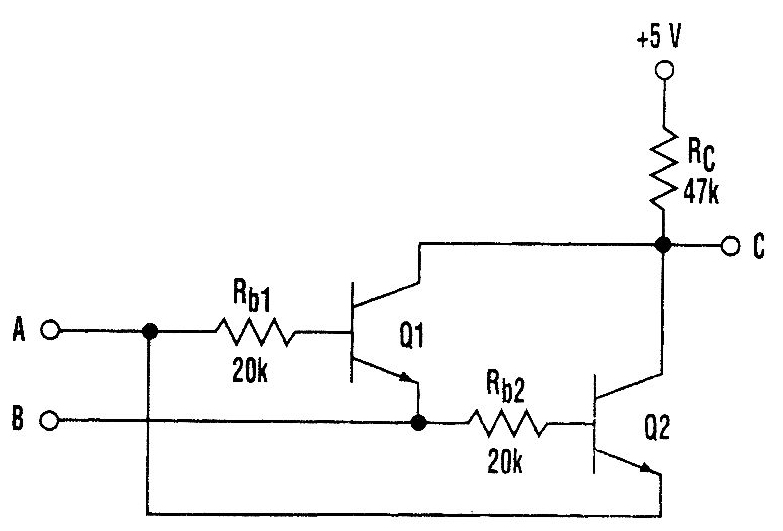
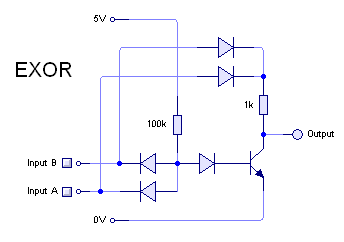
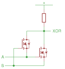
I sometimes find a small circuit with 3 resistors and 2 transistors that performs the eXclusive OR operation.
These two interlocked transistors use a very unusual structure, which requires the least theoretical number of switching elements, but it depends on a trick : the input impedances matter a lot and the circuit depends on a "hard" 0 level, because the circuit behaves almost like a "pass" element...
Thus, the question : is it the best method ? What about the switching speed or the capacitances ?
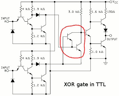
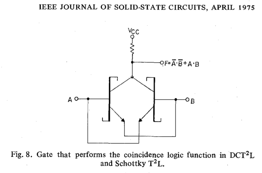
XOR is pretty important in CPUs because many mechanisms rely on it, for example ALUs. Does the gain in parts count affect the performance ? Apparently, it's pretty close to ideal because it's touted as a solution in Direct Coupled Transistor Transistor Logic:
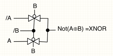
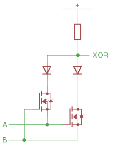
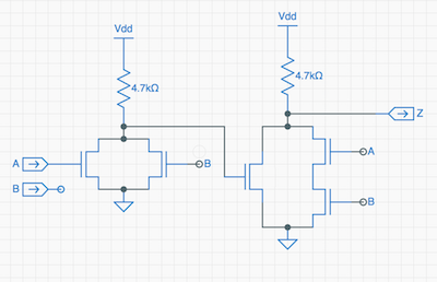
Another version has only one transistor but 4 diodes :
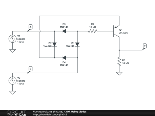
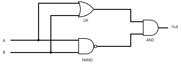
This is more or less what Rory does :
Another question is : can this scheme (no amplification, just relying on the input's strength) be extended to other logic or sequential functions ?
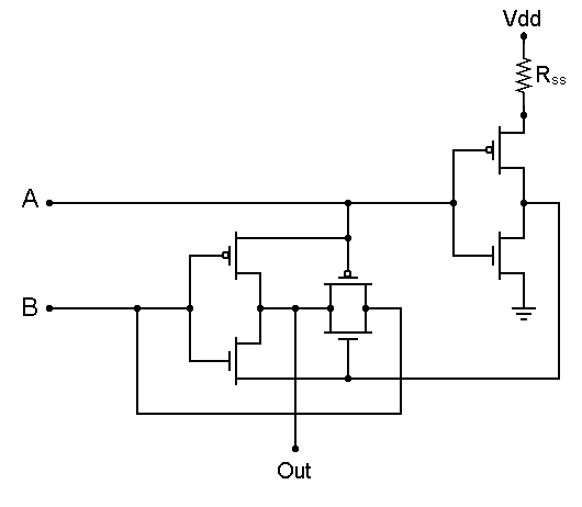
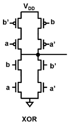
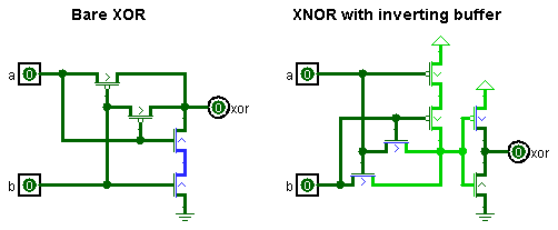
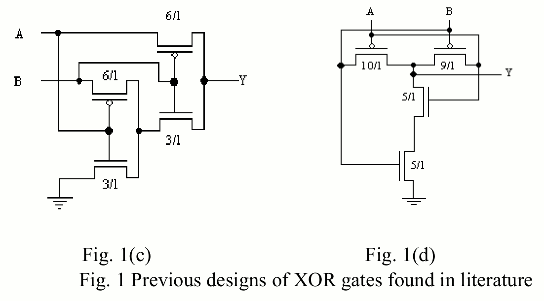
The XOR gate has a much wider range of implementations in MOS and CMOS. You can find circuits using 4, 6, 8, 9, 10 or 12 transistors, again with varied strengths for the inputs and the output. For example, pass-transistor logic (transmission gates) makes it pretty simple :
Each pass element is a pair of complementary transistors, so this gate uses 2 NMOS and 2 PMOS. Add as many if you want to isolate the outputs with inverters...
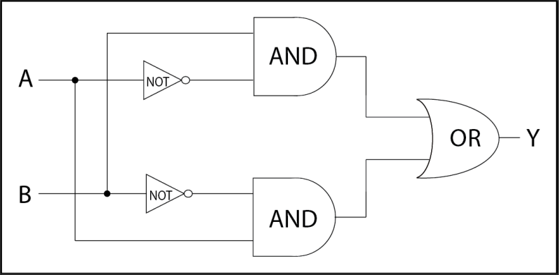
Oh and don't forget another inverter at the output. This is why you'll find various transistor counts. Unless the designer wants to decompose the function into elementary boolean functions, and the size explodes, depending on how you break it up:
 (also missing : picture with MUX2 and an inverted input)
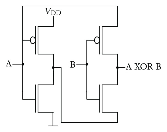
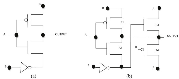
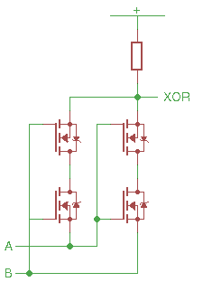
This decomposition leads to the "classic" CMOS XOR gate:
which gains weight again when the inputs are buffered and inverted :
XOR has a reputation of a "slow and large gate" for this reason and that's why I investigate smarter topologies and their compromises.
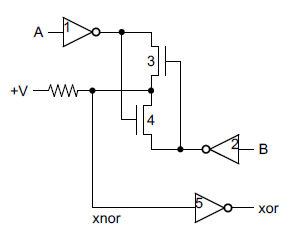
Another version is also pretty nice :
This is interesting for my #Yet Another (Discrete) Clock because it is almost suitable for MOSFETs. The B input must double the transistors because of the inherent diodes but it's "only" 3×BS170 and 3×BS250. In this case, the B input actually works as a multiplexer or transmission gate... Which means it might not be suited for ultra high speed.
Even fewer parts with this 3T XOR :
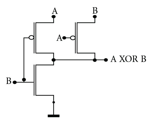
In this case, only 1×BS170 and 3×BS250 are required. It's still not ideal because the BS250 is more expensive than the BS170 but I don't see how to permute the polarities without requiring more inverters... Furthermore, there seems to be a conflict with one of the input combinations : B=1 forces the output to 0, but if A=0 then the input B (which is =1) is forced to 0 by itself... The solution is another PFET controlled by A, in series with the grounding NFET.
Another source https://waset.org/publications/1588/a-high-speed-8-transistor-full-adder-design-using-novel-3-transistor-xor-gates explains in great detail why the short circuit is not such a big deal for ICs : they tune the width/ratio of certain transistors to minimize the unwanted current. This trades space for power consumption.
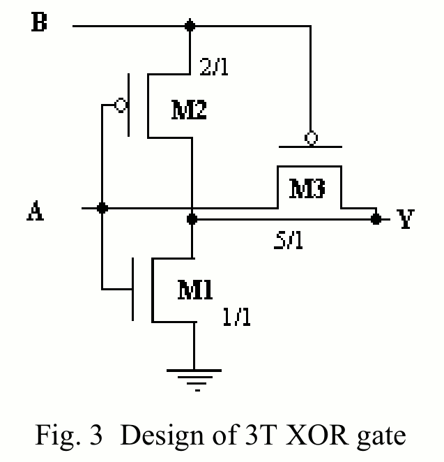
M1 has a 1/1 ratio, almost a square, wih minimal size, hence highest resistance, while M3 has a high ratio to overcome the pull-down from M1. For very high-speed CMOS circuits, where power is dominated by switching (and leakage for the newest processes) this short current can be considered "negligible".
Another interesting compromise uses only 2 of each type:
But the "upper pass trick" on input A might still need doubling of the P-MOSFET to cancel the parasitic body diodes. This could be cheaper if XNOR was made instead, so 2 PFETs are tied to Vcc in series, and the NFETs are used as pass elements.
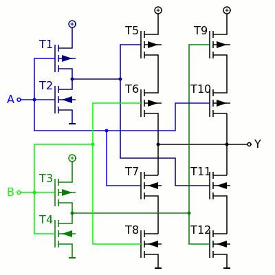
ICs use even more variations on these ideas:
 This odd one seems to interlock the leftmost transistors, followed by a NAND and finally an inverter:
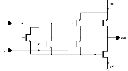
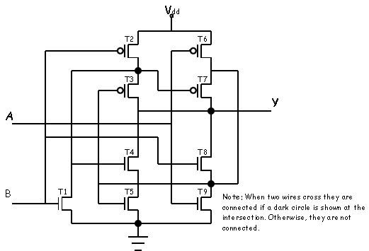
An enhanced 9T XOR:
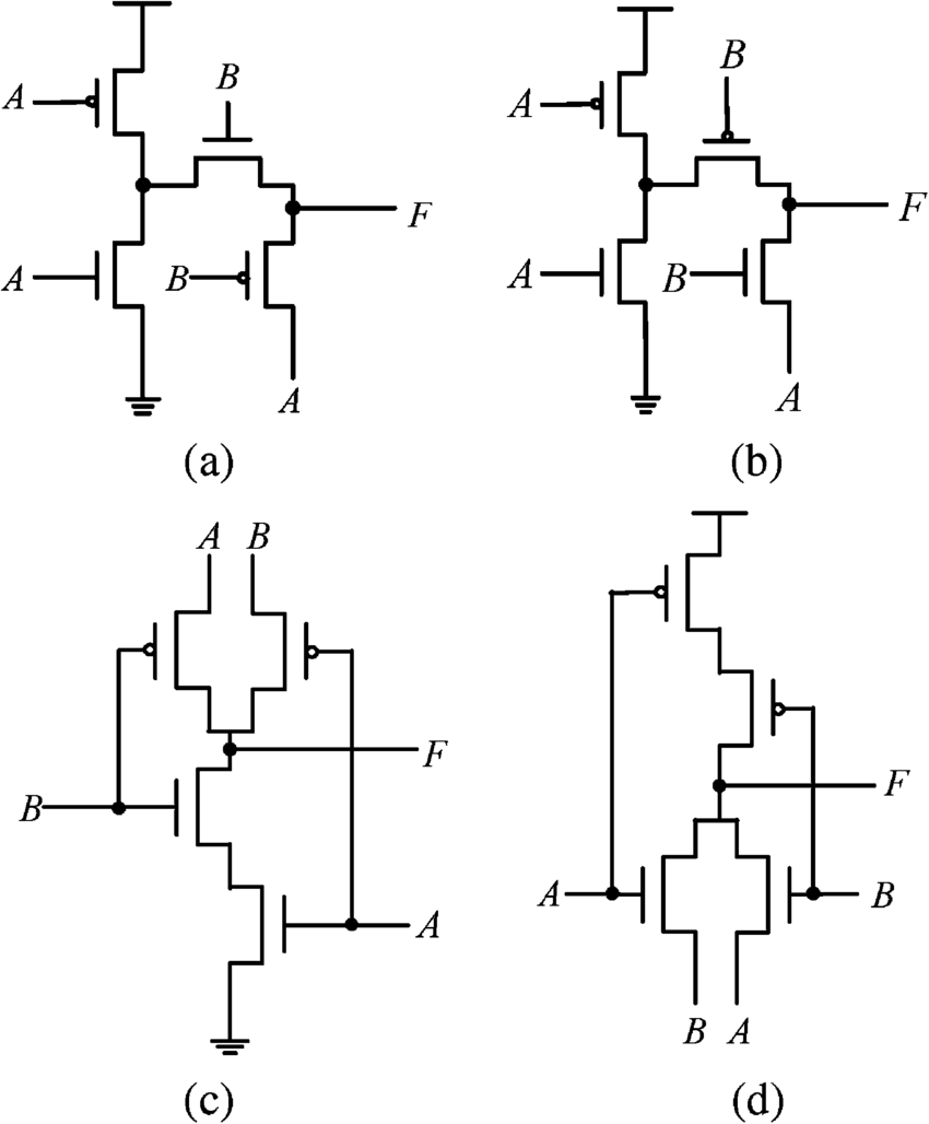
 Even more combinations with pass transistors :
 From https://waset.org/publications/1588/a-high-speed-8-transistor-full-adder-design-using-novel-3-transistor-xor-gates:
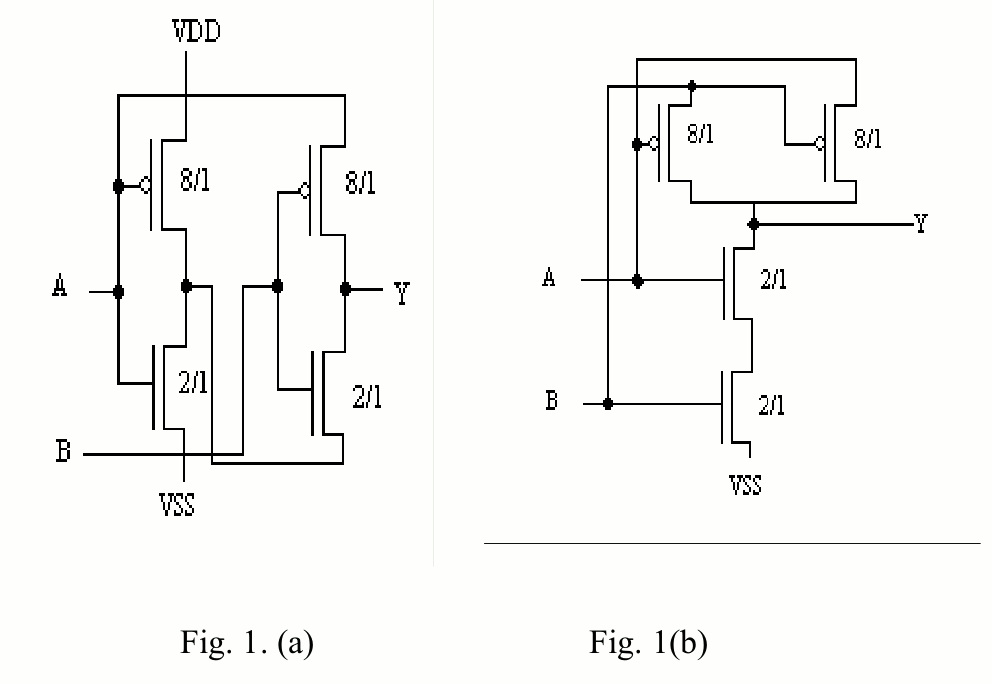
But I have not seen such variety for bipolar circuits.
ECL can use some creativity as well but these gates require many transistors anyway so it's not as interesting.
I have however wondered how to modify the differential amplifier to perform this operation...
I still can't find an answer about the bipolar case but I could easily adapt the interlocked system to MOSFET, in a bid to avoid P-MOSFETs. Naturally, this gives :
A rough simulation shows that there is a conflict through the parasitic body diode when the inputs are opposite.
One cheap way to avoid this case is with the insertion of diodes in series, to prevent one input from shorting into the other :
Here is the simulation with Falstad.
or for the purists : cancel the body diodes with back-to-back N-MOSFETs :
It would work at a lower supply voltage and the simulation shows the low state has a lower voltage but the speed would be 2x slower because the FETs in series double the ON resistance...
OTOH : if you want XNOR instead, just flip the circuit upside down and use P-MOSFET :
spudfishScott uses 5 NMOS for his XOR at https://hackaday.io/project/162814-the-spikeputor/log/157607-building-blocks-2-multiplexors-and-flip-flops:
Update :
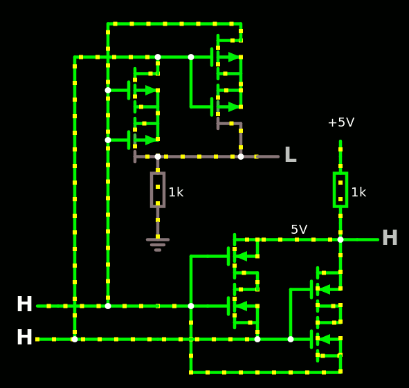
Master Ken reverse-engineered the Z80 at http://www.righto.com/2013/09/understanding-z-80-processor-one-gate.html and found a NMOS XOR :
Discussions
Become a Hackaday.io Member
Create an account to leave a comment. Already have an account? Log In.
The circuit on the second picture behaves as an xnor gate. If i inverted the output so i've got an xor gate. Three Transistors and 4 Resistors and it works.
Are you sure? yes | no
yes, and as noted in other comments, you need to restore the levels, hence the 3rd transistor, otherwise you can also do "bubble pushing" to propagate the inversion downstream or upstream
Are you sure? yes | no
After using this cross-coupled pass gate XOR gate in actual circuits, I have to say that the image on top of this log is highly misleading.
The input and output drivers are a MUST to properly restore logic levels and driving strengths. So it's not really a 2 transistor XOR gate, but more like 4-5.
Are you sure? yes | no
More XORs from Ken, AGAIN !
https://www.righto.com/2023/12/386-xor-circuits.html
Are you sure? yes | no
The first 2 transistor XOR actually behaves like an XNOR gate when built in Falstad simulator. I used NPN and 5V supply/logic HIGH, is this correct?
Are you sure? yes | no
Send us the link or schematics file on the public chat so we can look at it :-)
Are you sure? yes | no
https://imgur.com/a/lVNoeLa
Are you sure? yes | no
Usually this type of gate requires an amplifying stage, which is usually an inverter as well, so the whole does a XOR. Unless the fanout is only one and you modify your circuit to handle the XNOR...
It's a wild guess... But the XOR circuit is pretty forgiving, as you can either negate either input, or the output :-)
Are you sure? yes | no
you can export a schematic as a link from within Fasltad :-) it's in the File -> Export as link menu.
Are you sure? yes | no
http://www.falstad.com/circuit/circuitjs.html?ctz=CQAgjCAMB0l3BWcMBMcUHYMGZIA4UA2ATmIxAUgpABZsKBTAWjDACgAXcMFcQqsDRp8qAkExiEakBEULYsgyLmEZo02YXk4E2QjhQJmxZFQAmDAGYBDAK4AbDpxAppIl-ndiJ0KTLkKGEoqIGoaATp6BsamIBY2Dk4A7uBCqcJgGITpUGwpmdmCGVngKHi5+SVFHuXVkHngVWUg2Gil5fUATo2FzQW0HaZwbN2svGD8A15DXS2QGZOuApMC8PUASj1T-RNQe25IolDQCGwAMtuTuxNHVDb2AM4M1PUpNLWT7+DEvK-bPzVvr8GmhagDQVs-tUdmkIVDYZ4QnCGkjEfMvA1qhCvsiLjjPLs4Xt7k8XmwALItWTcXjSAQ8PYoE7OVoCZrYak8QYQGAIDDzHA0BB4QQIQSEDq+cJaIWsH7ECWxeJ2RwozlpDnjEr1ADmVK12U1QL2syNY31U1WwxSRq+-S+9SAA
The XNOR part can use higher resistors to draw less current and prevent saturation while the output stage inverter can amplify the result.
Hope this helps :-)
Are you sure? yes | no
Thanks! That will work great!
Are you sure? yes | no
@69K-ram I hope so :-)
Are you sure? yes | no
Just curious, are there extant (reasonably available) MOSFETs *without* the internal diode? That might be a useful path of exploration...
Are you sure? yes | no
CD4007 and JFETs. Almost all other "normal" (planar) discrete MOSFETs have been discontinoued, outside of a few hardly obtainable niche products.
All other devices are LDMOS devices and more complicated variants thereof.
Are you sure? yes | no
the JFETs available today (are we talking about the BF245 ?) have an inverse mode of operation so can't work like the usual MOSFET...
Furthermore the internal diode is the parasitic effect of connecting one side of the FET to the "bulk". I have heard that there might have been some references with a separate bulk but I have never see anything in a catalog.
Are you sure? yes | no
>JFETs available today (are we talking about the BF245 ?) have an inverse mode of operation so can't work like the usual MOSFET...
Yeah, JFETs have a normally on operation since the channel is pinched off by the applied gate bias. But the benefit is that they are truely symmetric and can be used as pass-gate transistors. The logic has to be adapted a bit due to the inverted operation - tbh i also have not though about that so far :)
One issue is that most JFETS are for fairly low power.
>Furthermore the internal diode is the parasitic effect of connecting one side of the FET to the "bulk"
That's actually an intrinsic design element of power mosfets. There are no planar mosfets on the market, since there is almost no need for them in discrete form. I looked into this in detail a while ago. Should start a log.
https://en.wikipedia.org/wiki/Power_MOSFET
Are you sure? yes | no
A lot of the "odd" CMOS ones seem to revolve around restoring logic levels and meeting margins.
Of course, such things can be predicted much better on an ASIC where you have 3-sigma device models.
The analysis in the linked paper is nice.
Edit:
That paper is actually cheating a bit with the transistor count: https://cdn.hackaday.io/images/8079621600927911414.ef9c7d73b06c9f38cae6b3bf15a8a5df. There is a weak path where a ripple carry would lead to incremental device stacking.
It also seems they only simulated the isolated circuit...
Are you sure? yes | no
I wish Falstad's circuitjs let us simulate these sorts of transistors :-)
Are you sure? yes | no
Well, you could use LTspice, NGspice or TIs free PSpice version.
1µm and 50nm CMOS models are available, f.e. from here: http://cmosedu.com/cmos1/book.htm
You can also manually import models from foundry PDKs, but getting access to those usually requires an NDA.
Are you sure? yes | no
Maybe the Skywater deal will help on that subjet...
Are you sure? yes | no
I have only seen digital libraries, no spice models.
Are you sure? yes | no
You thought it was too many XORs ? well, here are even more !
http://www.vlsitechnology.org/html/cells/wsclib013/xor2.html
Are you sure? yes | no
Thanks for this inspiring article. Here is my take on this in LTL (LED transistor logic) trying to address some signal integrity issues. Should also work in DTL.
https://hackaday.io/project/169948-lcpu-a-cpu-in-led-transistor-logic-ltl/log/174037-xor-gates
Are you sure? yes | no
thanks :-)
Are you sure? yes | no
Thanks so much for this page. I have worked on this a bit and written it up https://hackaday.io/project/19386-the-blinking-computer/log/159454-3-input-xor-in-4t-2r
Are you sure? yes | no
If you can do one XOR, you can do two ;-)
The "interlocked BJT" needs a clean path to 0V so I'm not sure that chaining two such structures is efficient, the voltage swings might be uselessly large ?
@matseng seems to have examined this :-D
Are you sure? yes | no
Could do this in 2 optoisolators, but it'll be really really slow like a few microseconds or even more. :P
Are you sure? yes | no
muahahahaha :-)
and with relays : only one ;-)
Are you sure? yes | no
The ones I have comes with built-in freewheeling diode and therefore polarized.
Are you sure? yes | no
*sigh*
Are you sure? yes | no
BTW you might have missed my comment on ECL Xor using a diff. amplifier below - 3 days ago
Are you sure? yes | no
Maybe, as notifications sometimes get lost in the mail... I'll look.
Are you sure? yes | no
Another neat XOR: the one-transistor XOR gate. I've built this in hardware and it works well, but there are some quirks.
https://www.circuitlab.com/circuit/q5y7c5/xor-using-diodes/
Are you sure? yes | no
I've seen this in an analog circuit and I was puzzled at first... But it's worth a mention !
Are you sure? yes | no
Of course this interesting thing about ECL is that inverters are essentially free, which brings an (A&~B)|(B&~A) style XOR implementation down to being only slightly more complex than the traditional TTL version... that said, I'm convinced there must be a sneaky way to implement it using balanced inputs into a differential amplifier and detecting whether or not they're equal...
Are you sure? yes | no
Yes, there MUST be a way.
Wait, what if I looked at actual ECL circuits ? :-P
The one I know is made of a MUX2, with 2 different driving levels, but I suspect it's not the only possible topology :-D
Are you sure? yes | no
See figure 1 in https://www.pulseresearchlab.com/pages/necl-pecl-faqs
>Q1 and Q2 are normally referred to as the differential switch. In the steady state, either Q1 or Q2 is on but not both, and the output logic state is determined by the voltage difference between the bases of Q1 and Q2. If Vb1 – Vb2 > 200 mV, Q1 will be turned on and Q2 turned off, and vice versa.
What if you feed the non-inverting signal of the two XOR operands into the True & Complement inputs of the differential receiver and tie the output for Q1 and Q2 together - wire-Or the output ? My brains can't run a spice simulation.
Are you sure? yes | no
@K.C. Lee I've had the similar thoughts, to replace the voltage reference with another input. But I doubt it's enough... I must miss a few elements... It'd be better to check the Motorola books :-)
Are you sure? yes | no
@Yann Guidon / YGDES You might be able to get it down to 3 transistors by joining the collectors of Q1 and Q2 and only using of the Q3/Q4. Don't know for sure until a spice simulation.
Are you sure? yes | no
Using balanced inputs to an analog circuit, producing the XOR.... This is a double balanced mixer, known from RF engineering. An example is the https://en.wikipedia.org/wiki/Gilbert_cell .
Since analog systems are balanced around zero, logic 0 is for instance +1volt and logic 1 is -1 volt (In practice, lower voltages might be used).
The balanced mixer multiplies the two input signals (btw, these inputs are in many cases differential). So:
+1 * +1 --> +1
+1 * -1 --> -1
-1 * -1 --> +1
You see that the output is only logic 1 (-1V) if the inputs are different. So thats XOR !
You will find that the Gilbert cell uses a transistor circuit that looks very much like digital transistor circuits.
Are you sure? yes | no
You can certainly use the two-transistor (plus pull-up) case in NMOS but you do need to watch your logic levels. See for example section 5 here:
http://pastraiser.com/technology/nmos/basicnmosgates.html
I'd like to be able to point to such a case on the 6502, but I can't. There is a mux-based one though:
http://visual6502.org/wiki/index.php?title=6502_increment_PC_control
Are you sure? yes | no
Damn, this XOR thing can never be exhausted :-P
Thanks for the links !
Are you sure? yes | no
The Z80 has an interesting XOR gate - and Ken Shirriff links to a couple of others too. See here: http://www.righto.com/2013/09/understanding-z-80-processor-one-gate.html
Are you sure? yes | no
5a is indeed used, then ! that's interesting to know :-D
What a crazy logic gate zoo :-P
Are you sure? yes | no
That is really cool! Glad I read it.
Are you sure? yes | no
I'm glad my explorations and inquiries help other TTLers :-D
Are you sure? yes | no
wow, very very interesting!!
Are you sure? yes | no
"it ain't but a scratch"...
I did only a few image searches. And I'm puzzled
Are you sure? yes | no