Yes, the wait is over! Part 2 has finally arrived!
In this log, I’ll summarize the design process I went through with Eagle and later KiCad with the control and sensor board replacements for the Power Glove. To be honest, this information is a bit outdated as I have already received the boards mentioned herein, but I feel obligated to catch up and put out a full build log. If you’re not interested in the design process and want to see some results NOW, hang tight! I’ll be posting a log with the boards and current prototype soon. Otherwise, have a sit in your favorite chair (or other accommodating local seating), relax and read on!
Getting Started in Eagle
The initial design was very simple, yet perhaps slightly over engineered. It featured a standard ATmega328P-based Arduino as the brains for ease of design. FTDI and ICSP headers would be provided for programming and debugging. SPI GPIO expanders (MCP23S08 and MCP23S17) would be used to collect the button inputs, taking advantage of the chips' interrupt features to eliminate the need for polling. 5V from the FTDI cable would power the Arduino as well as a 3.3V LDO for the external sensors. Any sort of expansion port to provide additional features or extra prototyping capabilities was absent.
After taking initial measurements of the Power Glove's main control board, I drew up the board outline, placed mounting holes, created the spiral button pad footprints and marked said button pad positions on the board, attempting to stay as true to the original as possible. Unfortunately these measurements were made hastily in anticipation of getting the board fabbed quickly, and their inaccuracies showed when printing out the board layout for physical design checks. Still, I went ahead and began adding my previously chosen set of components to the board. The button footprints were initially on the top layer but were flipped to the bottom to follow the standard of placing components on the top layer. The ATmega, GPIO expanders and voltage regulator were added as SMD components, while through hole headers were used for a reset button and ICSP, FTDI and sensor board connectors. I started routing traced and made decent progress, but ultimately the board was left unfinished. The project was temporarily dropped when a project at work pulled me away and kept me constantly busy.

A Minor Detour
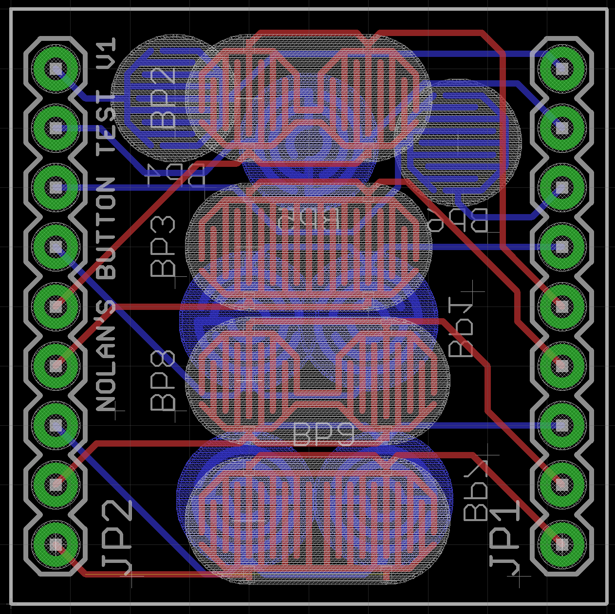
During the time away from the project, I had been looking into button pads on other controllers and remote controls and wanted to try some different styles. New octagonal button footprints were created, and a test board with various types of pads was hastily cobbled together with the idea of comparing the designs.
The board was manufactured by OSH Park but was ultimately unused due to a lack of time and perceived usefulness. Still, finally seeing the little gold button pads on a board of my own making was pretty neat.

The Button Tester Widget
Fly Like an Eagle: Round 2
When the project was picked up again sometime later, attempts to make new, more accurate measurements were made, resulting in a new board outline and adjustments of the button pads and mounting holes. The new measurements proved to be only slightly more accurate, but I was able to tune out my OCD and decided to continue with a vow to come back later and improve them. This version ended up retaining the button pads on the top layer
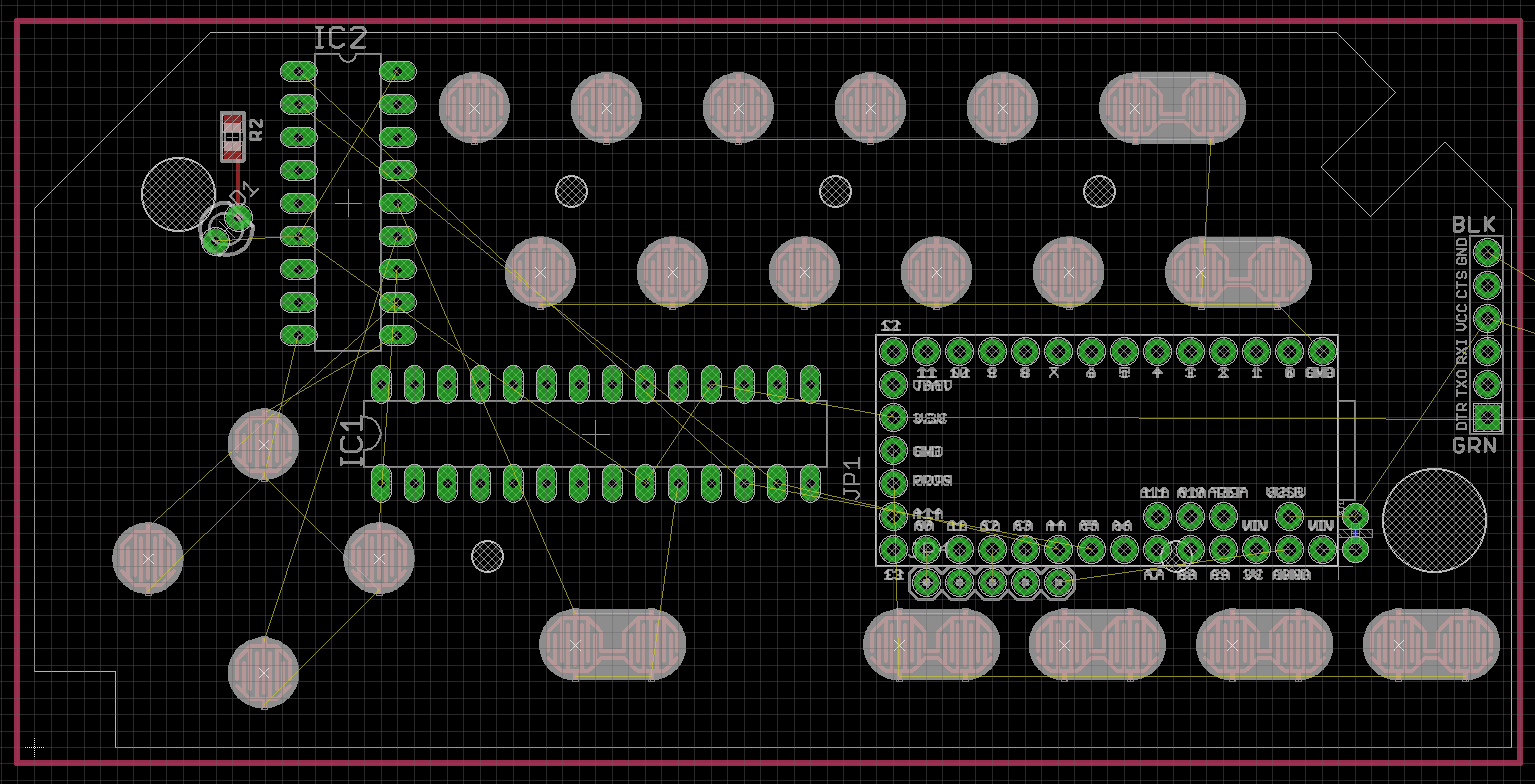
In the interests of getting a board on which I could actually begin protoptyping, a need for more through hole components was recognized. The ATmega-based Arduino was replaced with a Teensy 3 in anticipation of needing more computing power, and DIP versions of the GPIO expanders were used. An LED finally found it's way onto the board, occupying the same position as the original. Unfortunately I found difficulty trying to find convenient places for the components as the numerous button pads took up a large amount of space, and the thin enclosure of the board left little room for anything remotely tall. Due to having even less time, routing was never started, and the project was eventually put on hiatus once again.
The highly unfinished Control Board, version 2
In KiCad We Trust
A lot of time passed before the project was picked up again, but with more free time made available, iit finally would become an active project. In the time between, I had made a permanent jump from Eagle (and from Diptrace at my work) to Kicad. Learning the ropes of Kicad was fairly easy thanks to prior ECAD experience and various video tutorials by Chris Gammell. Many knock Kicad for it’s steep learning curve, and I’ll admit it does have its quirks (the library system mainly). Once you spend some time working with the software though, you come to understand how everything works, and Kicad reveals its true power and flexibility. I found the whole experience very rewarding, especially since it’s a free and open source. Eagle may be known as the average maker’s software of choice, but I highly, highly recommend giving Kicad a try, even for first timers.
Along the way, I picked up a valuable bit of wisdom when it came to designing boards: don’t worry about perfecting your design on the first pass and definitely don’t let OCD get the best of you. Statistically speaking, your first design is likely to have issues (my boards are no exception), so instead of spending time obsessing over the minute details of your design, use that time ensuring your design’s functional requirements have been met. For example, while taking my final set of measurements, instead of trying to match the original board’s size and shape perfectly, I made sure to accurately measure the mounting holes on the board as they were the most critical component of the physical design. From there, I drew the board outline more freely than I had in previous attempts and ended up with a useful design.
The same advice was used to create the button pad footprints. KiCad’s footprint creation tools leave much to be desired, but instead of worrying about perfect recreations of the pads, I used the tools given to create footprints that were functional and still visually appealing (they ended up being pretty similar to the originals anyway). Like the previous version in Eagle, the board was designed with the buttons face up, components on the bottom.
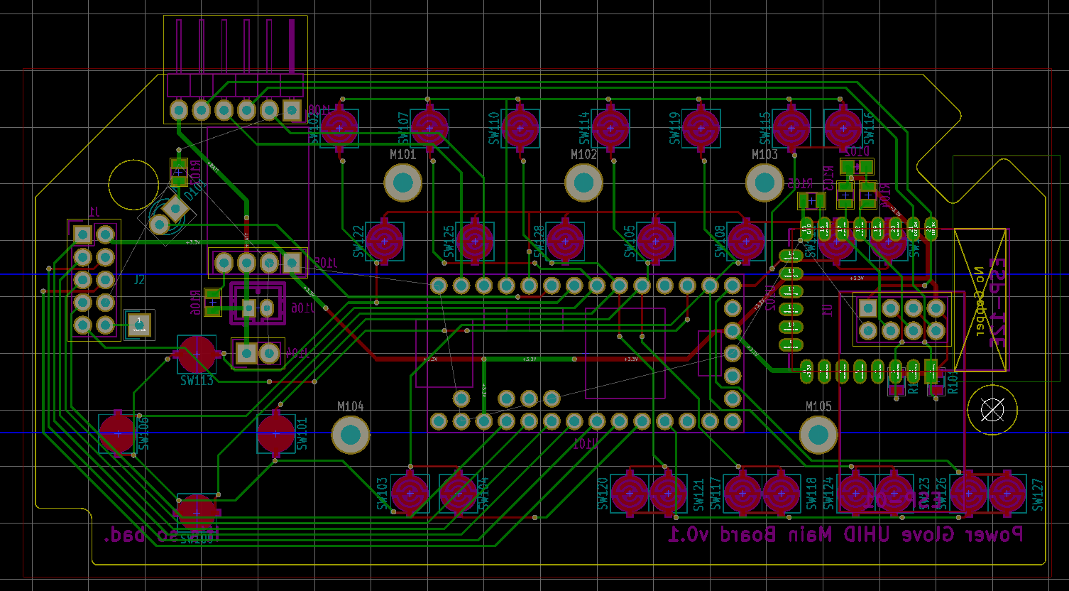
Finally satisfied with the physical design, I began to place my revised set of components, consisting of the Teensy 3, ESP-01/ESP-12E WI-Fi module, Pololu step up/down regulator and LiPo battery header. After a closer look at how the original board functioned, the GPIO expanders were replaced with the original keypad matrix, albeit with a custom layout designed for my setup. This allowed me to reduce parts count while paying tribute to the original design.
Being able to program the ESP module required me to break the device’s serial line away from its connection to the Teensy. This was accomplished by using a board edge header with pins that could be jumped to reconnect the serial lines during normal operation. Not an ideal solution, especially as the data rate increases, but quite functional.
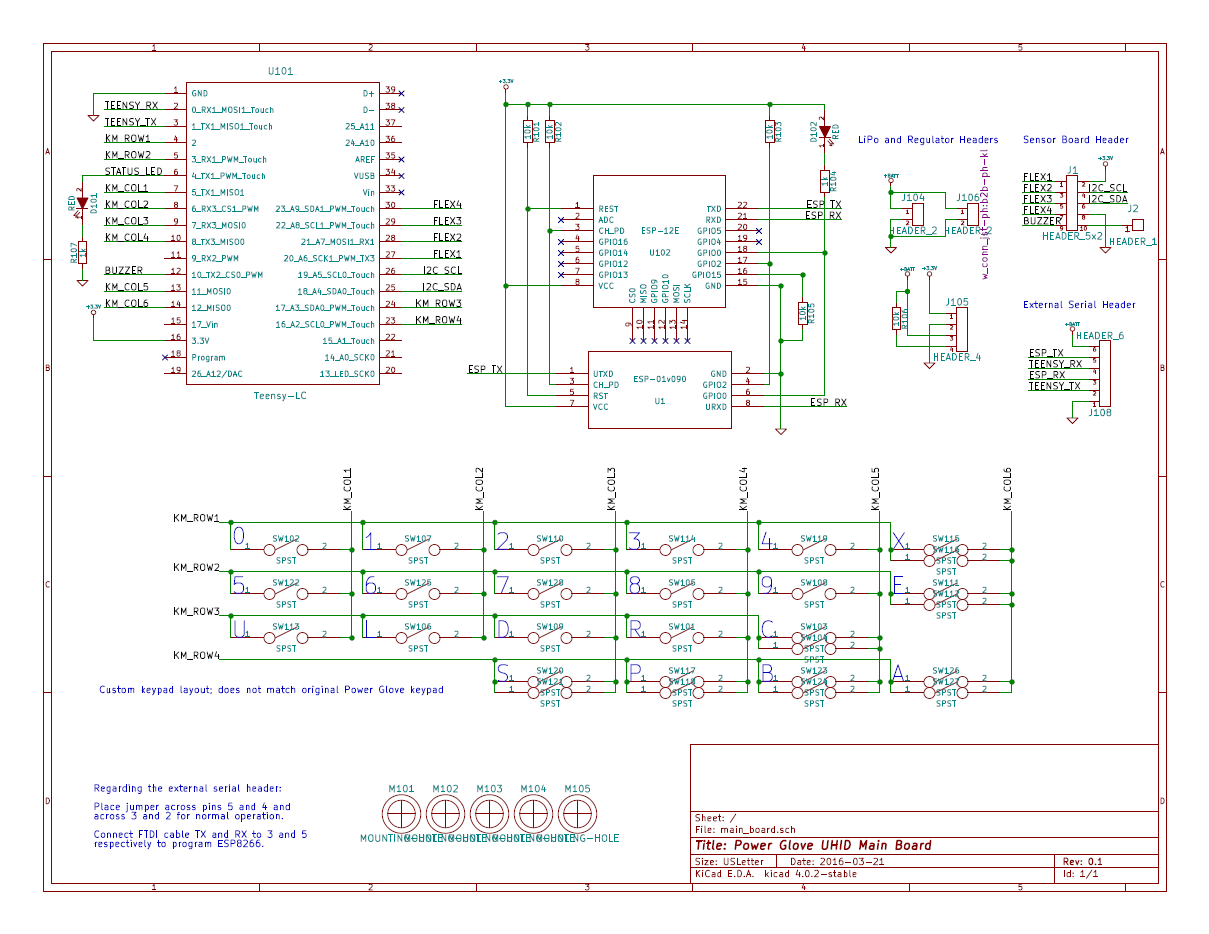
The much improved Control Board design
Laying out the PCB proved to be interesting, but not too much of a challenge. The Teensy could only be placed within a specific area where I had cut out a portion of the back of the enclosure (true sacrifices finally had to be made). The ESP modules were to be placed towards the edge of the board with no ground plane beneath the antenna for best reception. The ESP-12E has a simple solution, but the ESP-01 footprint, which was placed within that of the ESP-12E to better utilize the space, failed to fully realize this and did have a ground plane beneath its antenna (though tests have shown no issues as of yet). The serial breakout header was placed in the best remaining position at the top, but the header, as well as the regulator beneath it, forced me to make further cuts in the enclosure.
With all the components in place, the routing began, and it wasn't long before the board was completed! I plotted the Gerbers and sent the design off to board manufacturer Accutrace (a.k.a. PCB4U.com) for prototyping.
The finished Control Board, version 3 (v0.1 in Kicad)
Designing the Sensor Board
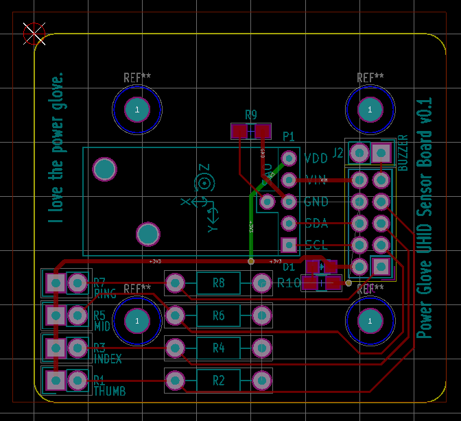
It was a huge relief when I was able to finally began designing the sensor board replacement. The sensor board was very simple, consisting of a Pololu 10-axis IMU module, voltage dividers for the flex sensors and a header for connecting to the control board.
I began designing the board with the idea of replicating the original as had been done with the main board, but after seeing a manufacturing special at Seeed Studios on 5x5cm boards, I decided to shrink the design down to a minimal size to fit my prototyping requirements. Following in the design footsteps of the control board, the mounting holes were measured and placed before drawing the board outline.
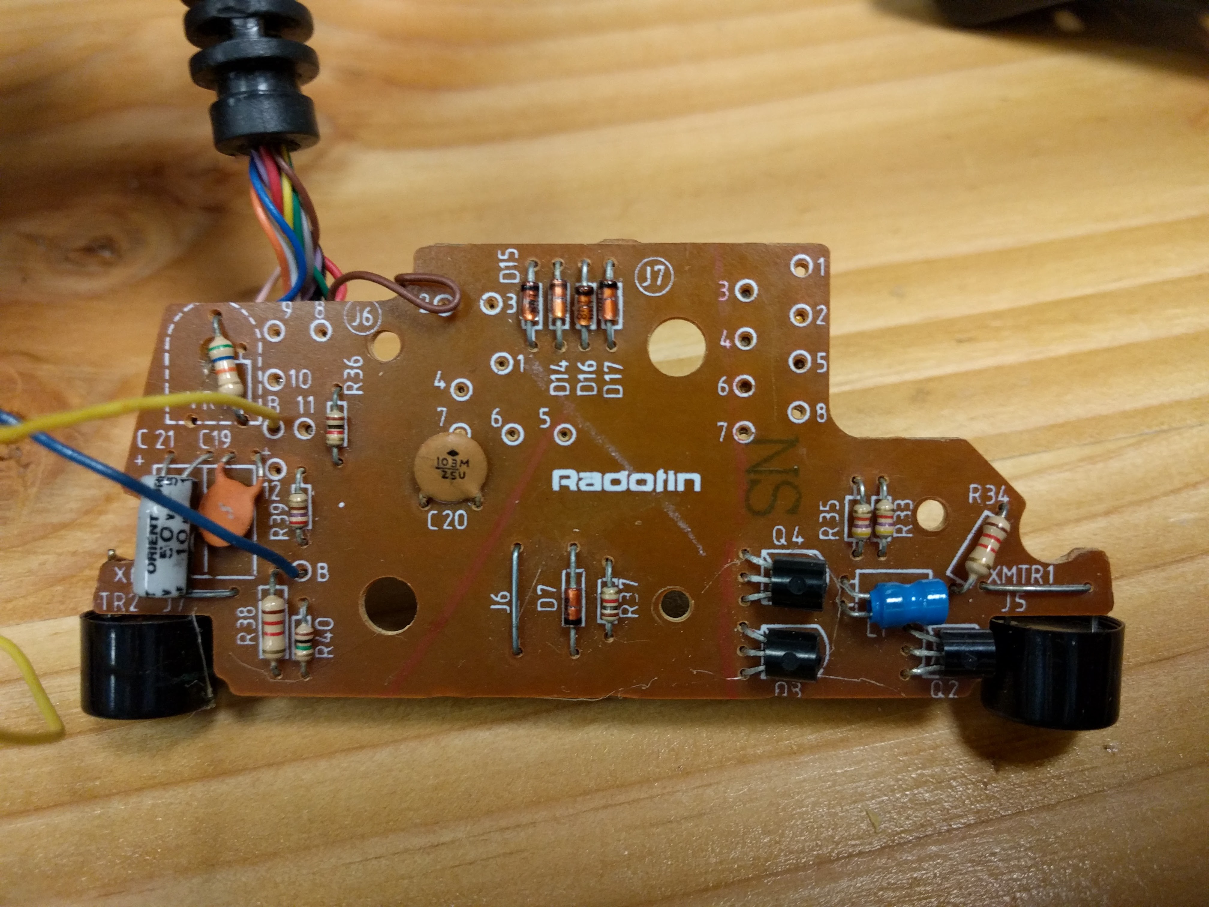
The Original Power Glove Sensor Board
The PCB was quickly laid out and tested for proper fit in the glove enclosure, and with that, the board was finished, making it one of the quickest and most simple designs of mine to date. I quickly sent it out to the manufacturer and settled in for the long wait.
Sensor Board v0.1
Hindsight And It's Perfect Vision...
Not long after submitting both boards, the inevitable issues began popping up, though most it seemed would be a matter of inconvenience rather than true problems.
On the control board, the ESP modules were found to be missing both a reset button and bootloader button, meaning that programming required opening the enclosure to pull the ESP's GPIO0 pin low while hard resetting the power rail. And as mentioned previously, the ground plane beneath the 01 should have been removed (alternatively, it could potentially be rotated to match the orientation of the 12E module).
The sensor board had but one issue: at least one of the mounting holes was to be an actual hole through which a screw could be fastened in the bottom of the enclosure. These could be ignored for testing, but would be necessary for the final working model.
It was unlikely that these would be all the issues I would encounter, but with boards in manufacturing, I could only give myself a pat on the back and be thankful none of the issues were critically bad.
Next time, real boards!
 Nolan Moore
Discussions
Become a Hackaday.io Member
Create an account to leave a comment. Already have an account? Log In.