 Gary
Gary-
1Step 1
WARNING................................WARNING.................................WARNING...............................WARNING
WARNING................................WARNING.................................WARNING...............................WARNING
This project uses 110v mains power and can be dangerous or deadly... Make sure you know what your doing. If your not comfortable with working with 110v AC dont do this project. Make sure when you testing you insulate 110v connectins and keep your hands away from any exposed wires.
WARNING................................WARNING.................................WARNING...............................WARNING
WARNING................................WARNING.................................WARNING...............................WARNING
-
2Step 2
NOTICE:
THE ESP 8266 is a 3.3v device. DONT connect VCC or any of the pins to a 5v source or it will damage the device
NOTICE
-
3Step 3
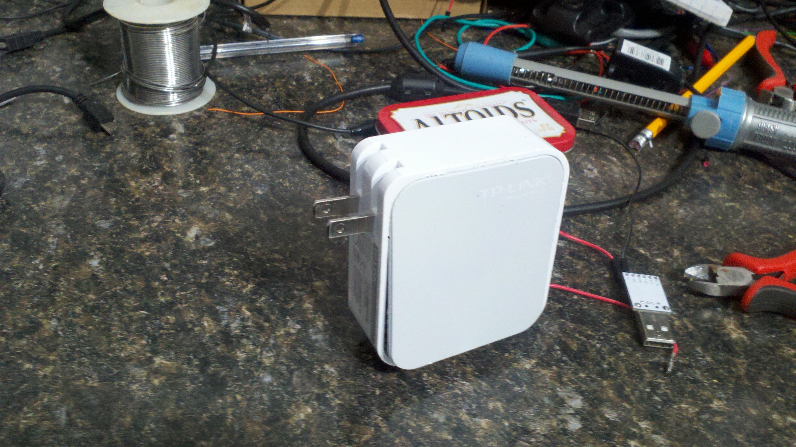
The first step is to find a case to house the parts in. I had an old TP-link router case that I used. It already had a two prong spring out 110v connections but any box will work. When planning your boxes figure out how your going to get the AC in and out of the box. A stop at your local bigbox hardware store should give you lots of idea. At a minimum a deepwall outlet/switch box will work but use your imagination. My project only uses 2 wire as thats what the case supported but if your planning on switching anything other than simple lights use a 3 wire system and include the ground.
If your not sure about what wires goes where take a look online on how you would add a simple manual switch to a circuit and just replace the switch with your device.
![]()
-
4Step 4
This project requires some software to setup your esp8266 with LUA firmware and a way to program the LUA code onto the esp8266 chip itself.
Here are a couple of links for getting the LUA firmware and lua programming IDE.
You need to be able to flash new firmware to the chip., To do that I recommend espflasher available at https://github.com/nodemcu/nodemcu-firmware
For loading the actually wifi detection software onto the esp8266 wifi board I would recommend ESPlorer available from github. https://github.com/4refr0nt/ESPlorer
A good overall source of information on the esp8266 chip and programming can be found at http://www.esp8266.com/
-
5Step 5
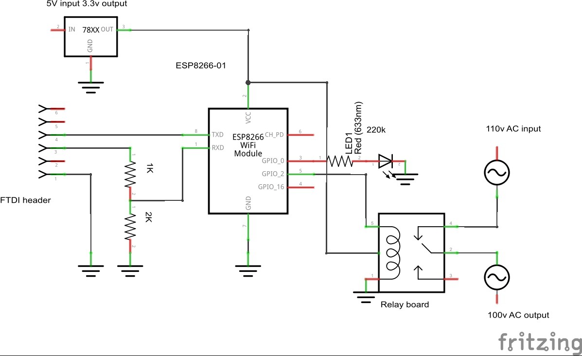
re is a schematic of the project. I took some liberal view on some of the items as I didnt have fritizing modules for all the specific parts I needed The basic flow is a 5v source provides power to a regulator to provide 3.3v power the device. The esp8266-01 runs code and controls a LED and relay board. The schematic shows a relay, but in reality it was a relay board assembly. I also used a 110v to 5v conerter to feed the voltage regulator. (not shown on schematic). You can get specifc device or tear apart on reuse and old 110v cell phone carger. Note, the ftdi connection and resistors from the header to the esp8266 are only needed during programming and dont need to be part of the final circuit.
![]()
-
6Step 6
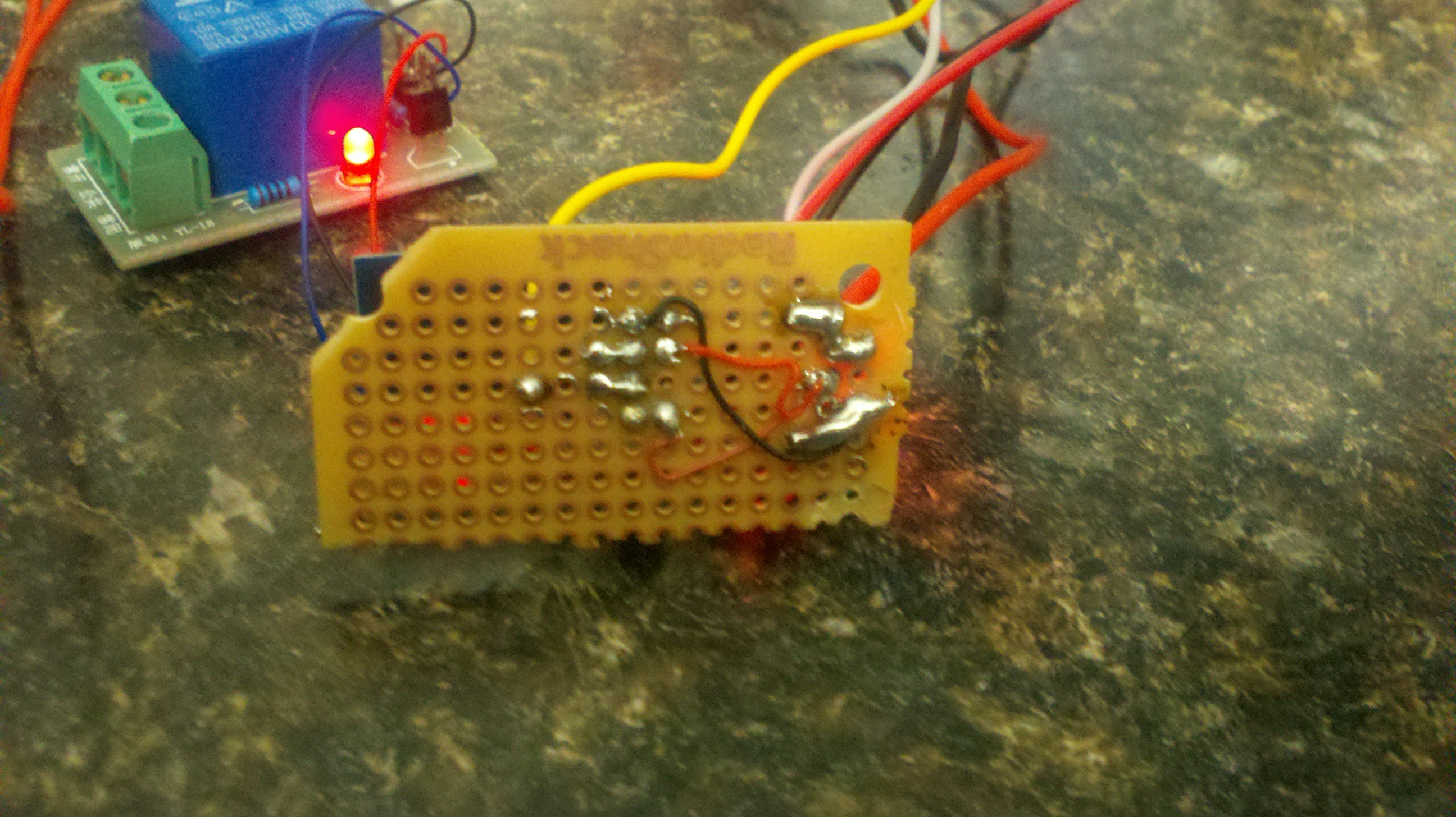
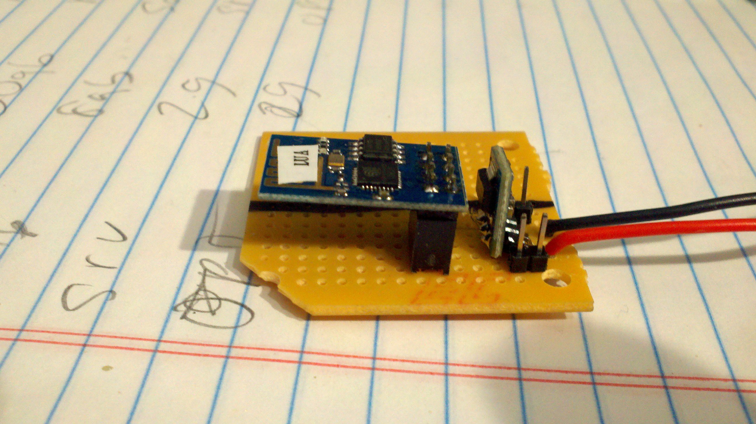
Build out the esp8266 module. Size as needed for your space. I use some 20g wirewrap to inter connect the parts.
![]()
![]()
-
7Step 7
I load the following lua code onto the esp8266 chip using ESPlorer. If you want to customize what the web page looks like then modify the outbuf variables . The included code with give you a box and a couple of buttons. CODE BELOW;
--Outlet control code for hackaday article.
--Gary Sanders, N8EMR
--
--setup the GPIO and set both low.
--
debug=0 -- 0 for no debug, 1 for debug messages
WIFI_ATTACHED_LED = 3 -- Port to use for WIFI status
RELAY_CONTROL = 4 -- Port to use for RELAY CONTROL
-- Set both ports to known state.
gpio.mode(WIFI_ATTACHED_LED, gpio.OUTPUT)
gpio.mode(RELAY_CONTROL, gpio.OUTPUT)
gpio.write(WIFI_ATTACHED_LED, gpio.LOW);
gpio.write(RELAY_CONTROL, gpio.LOW);
-- disconnect station/AP try to clearn an dhcp cache.
wifi.sta.disconnect()
-- Defined the HTML displayed when page is displayed.
outbuf = ""
outbuf = outbuf.."<!doctype html>"
outbuf = outbuf.."<html>"
outbuf = outbuf.."<head>"
outbuf = outbuf.." <title>PORT MODE</title>"
outbuf = outbuf.."</head>"
outbuf = outbuf.."<body>"
outbuf = outbuf.." <fieldset>"
outbuf = outbuf.." <center>"
outbuf = outbuf.." <h2 class='fs-title'>Turn outlet On or OFFF</h2>"
outbuf = outbuf.." <a href=\"?pin=ON2\"><button>ON</button></a> <a href=\"?pin=OFF2\"><button>OFF</button></a></p>"
outbuf = outbuf.." <center>"
outbuf = outbuf.." </fieldset>"
outbuf = outbuf.."</body>"
outbuf = outbuf.."</html>"
--Set the wifi connection with a Static IP address
print("Setting up WIFI...")
wifi.setmode(wifi.STATION)
wifi.sta.config("YOURSSID","WIFIPASSWORD")
wifi.sta.setip({ip="192.168.1.240",netmask="255.255.255.0",gateway="192.168.1.1"})
wifi.sta.connect()
print("Config done, IP is "..wifi.sta.getip())
gpio.write(WIFI_ATTACHED_LED, gpio.HIGH);
--Create a servers and give us a simple web page.
srv=net.createServer(net.TCP)
srv:listen(80,function(conn)
conn:on("receive", function(client,request)
local buf = "";
local _, _, method, path, vars = string.find(request, "([A-Z]+) (.+)?(.+) HTTP");
if(method == nil)then
_, _, method, path = string.find(request, "([A-Z]+) (.+) HTTP");
end
local _GET = {}
if (vars ~= nil)then
for k, v in string.gmatch(vars, "(%w+)=(%w+)&*") do
_GET[k] = v
if ( debug == 1) then print (" v is " .. v) end
if ( debug == 1) then print (" k is " .. k) end
if ( debug == 1) then print (" vars is " .. vars) end
end
end
local _on,_off = "",""
buf = outbuf --outlet control html
if(_GET.pin == "ON2")then
gpio.write(RELAY_CONTROL, gpio.HIGH);
elseif(_GET.pin == "OFF2")then
gpio.write(RELAY_CONTROL, gpio.LOW);
end --end if
client:send(buf);
client:close();
collectgarbage();
end)
end)
-
8Step 8
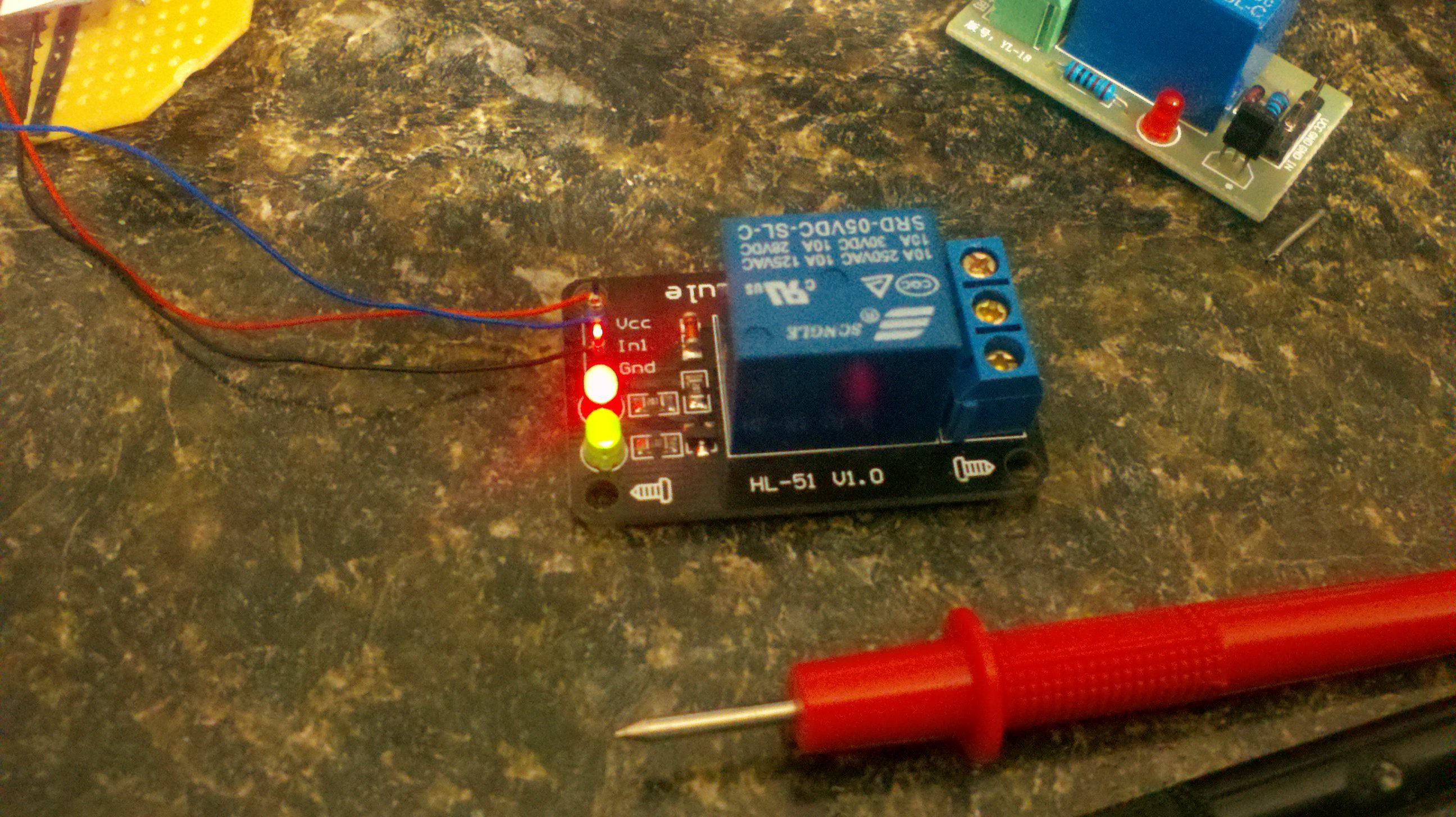
Wire up the relay board to the esp8266 . Because of my space limitations I didnt use any connectors on my wires so modules can be disconnected but if space permits I highly advise you add them. The relay board board take power voltage and ground in as well as a trigger/control wire in. The boards I have a "rated" for 5 volts but found they work fine in this 3.3v application. You need to provide 3.3v VCC, GND and input/control wire. The control wire goes to gpio2 on the esp8266
![]()
-
9Step 9
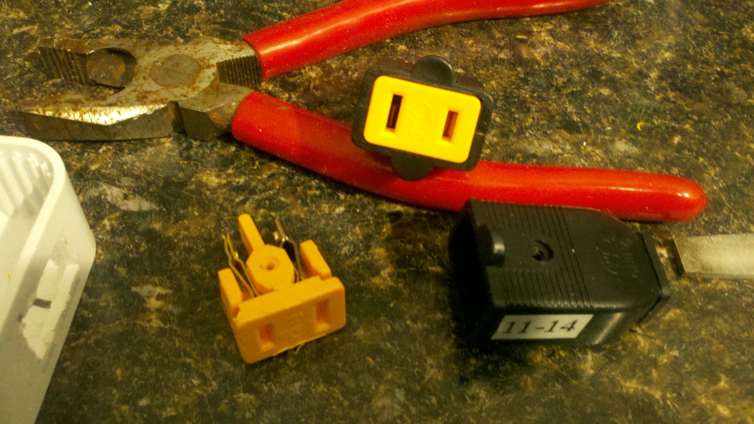
A trip to the local hardware store provided me with the 2 prong female connector I needed. I had to trip it up a bit to make it fit my case and trim down the connection legs but it seem to work fine.
![]()
-
10Step 10
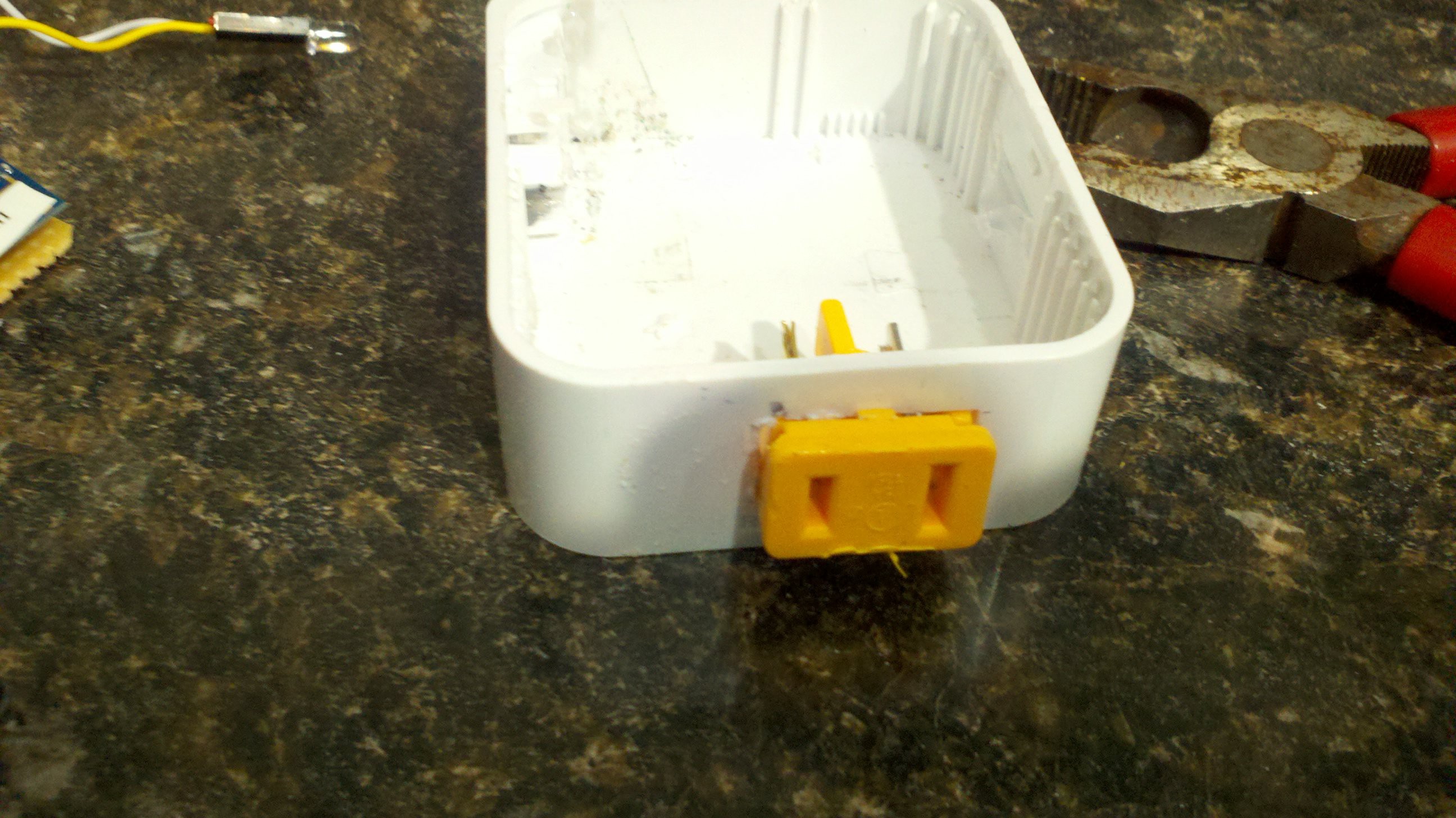
I cut my case to fit the new plug. Again triming the case and plug to fit tightly. Luckly the connector had a little lip to catch and keep it from being pushed into the case itself. I use dremel tool, plyers and some files to trim the case and connector to fit snug
![]()
ESP8266 lamp/outlet control
A simple project using a esp8266-01 that will turn an outlet on and off. With optional WEMO support for control with amazon alexa
Discussions
Become a Hackaday.io Member
Create an account to leave a comment. Already have an account? Log In.