 Gary
Gary-
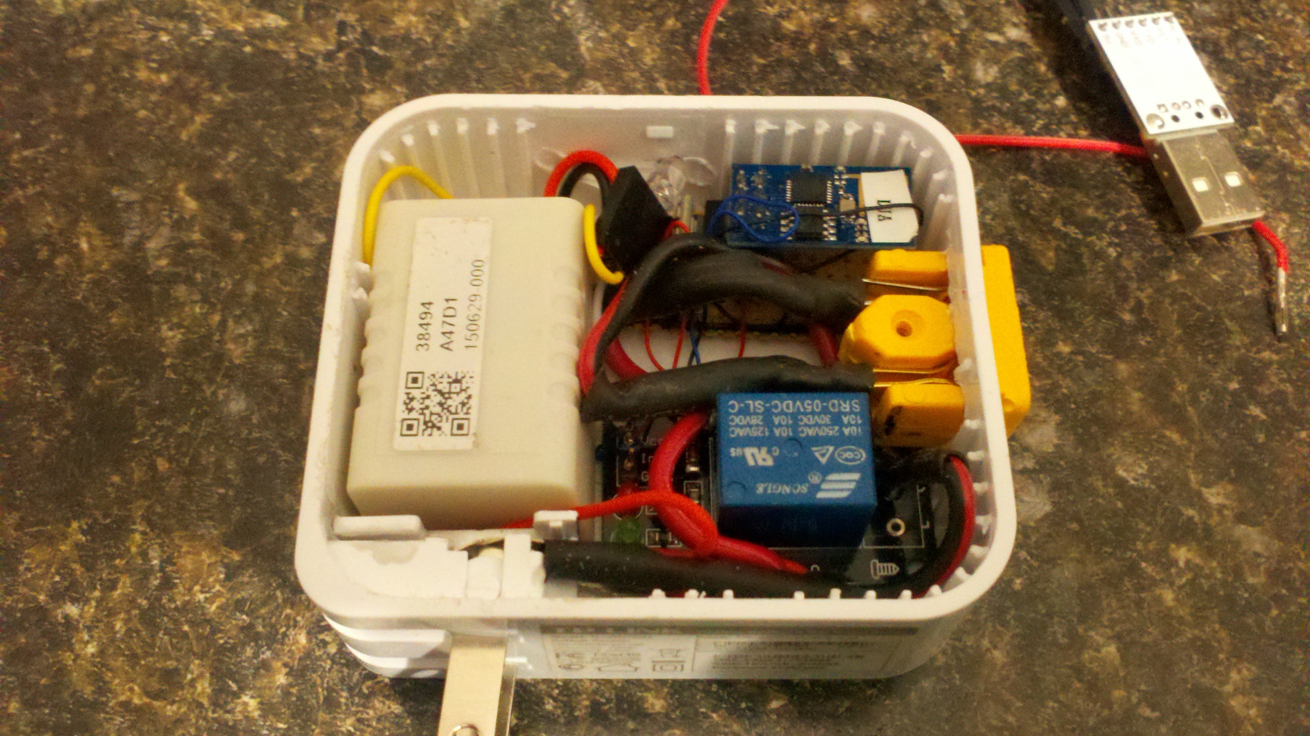
11Step 11
The last step way trying to cram all the remaining parts inside the case. this took a little work as the 110v wires are no overly flexable and take up some space.
![]()
-
12Step 12
Once everthing is packaged I spent some time checking continuity and making sure the 110v cables were not somehow touching any of the low voltage devices.
-
13Step 13
Once I was compfortable that It wasnt going to smoke test I plugged it into an outlet.. Confirmed I had power to the esp8266 and relay module.. Then attempted to connect to the IP address of the module. My code has a dynamic address of 192.168.1.240 but you can change the code as needed for your network. The page displayed and each time i pressed the ON or OFF button I would hear the relay click. After that test I plugged a table lamp into the model and pressed the ON/OFF buttons again to confirm the lighs would go on/off as comanded.
![]()
-
14Step 14
Project is now complete. Future changes, I would like to modify the code to startup in AP mode so you can enter your SSID and wifi password, No need to hardcode the password in the code. This will allow for quick setup and allow you to change the device password if your router password changes or you take your device to a new location. I am working on the code and will post it to this project when done.
Another future change is to use an esp8266-12 which will allow me more than the 2 ports the -01 module has. This will allow for more relays and more devices that can be powered on/off with a single module.
ESP8266 lamp/outlet control
A simple project using a esp8266-01 that will turn an outlet on and off. With optional WEMO support for control with amazon alexa

Discussions
Become a Hackaday.io Member
Create an account to leave a comment. Already have an account? Log In.