Close
0%
0%

HF receive converter for RTL-SDRs and similar

Converts 0 - 30 MHz up to 50 - 80 MHz. Allows HF(shortwave) reception on RTL-SDRs and the like. A square inch project entry

Similar projects worth following
A simple receive converter allowing you to listen to the HF bands on your VHF receiver, for example a $10 TV-stick RTL SDR.

Antenna feed is through a 30MHz low-pass filter to a CMOS balanced mixer where it is mixed with a 50MHz local oscillator to give a 50 - 80MHz output for a 0 - 30MHz input.

Power is taken from a spare USB socket.

This is an entry for the square inch project competition.

This is a simple upconverter, no rocket science.

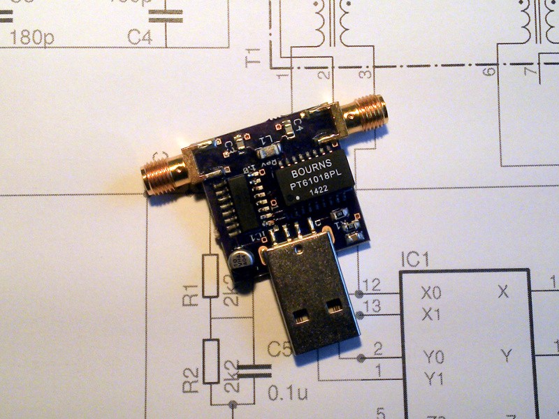
At its heart is a 74VHC4053 CMOS 2-pole analogue switch IC which is being used as a balanced mixer. Switching comes from the local oscillator, a 50MHz crystal oscillator. Each 50MHz pulse simply reverses the polarity of the connection through the mixer.

A dual Fast Ethernet transformer provides isolation and unbalanced-to-balanced conversion on the mixer input and output. These devices have a 100MHz bandwidth and are significantly cheaper than wideband made-for-RF transformers of similar spec.

This 74VHC4053/Ethernet transformer mixer is tried-and-tested, it forms the heart of my Pi-HF direct conversion receiver kit for the Raspberry Pi.

On the input is a 30MHz Chebyshev low-pass filter. This will reject any strong out-of-band transmissions.

The idea is that on the output of the mixer you'll find the sum of the signal and the local oscillator. So if you are listening on 14.1 MHz you'll tune the radio on the output to 50+14.1 MHz, i.e 64.1 MHz.

And here it is in use, the RTL-SDR is receiving an upconverted Croatian radio amateur in the 20m band:

  • 1 × 74VHC4053 Semiconductors and Integrated Circuits / Misc. Semiconductors and Integrated Circuits
  • 1 × 50MHz 5v 7mmx5mm SMD oscillator IMPORTANT! Make sure you get a 5V part and not a 3.3v one!
  • 1 × Bourns PT61018PEL dual Fast Ethernet transformer
  • 2 × Edge-launched SMA connector
  • 1 × SMD USB A male connector

View all 11 components

  • Kit progress so far

    Jenny List02/22/2016 at 08:05 0 comments

    This project has not seen the progress you might expect of late, as some other things have taken my attention and Chinese New Year has intervened as it always does.

    My updated boards arrived from OSH Park - https://oshpark.com/shared_projects/Vfd9X8z1 - and I built a second prototype. I'm writing this up somewhere else too, so a lot more tests were done.

    As I've said, I'll make this available as a kit in time. Probably before summer. It's sometimes a little difficult, managing the flow of new products in a small kit business, you have to sell a certain number of kits to be able to invest in new ones and there are one or two other products in the queue. So please, everyone, buy more kits! :) http://shop.languagespy.com/

    One thing I face making a kit from this is the cost of those SMA connectors. I can buy high-quality ones at a price, or I can buy cheap ones of dubious quality from your favourite Chinese online goodies bazaar. I am concerned that my connectors be of decent quality, I have seen some awful build quality masquerading as connectors and I don't want to unload that on my customers. It is definitely the case that not all SMA connectors are equal.

    So watch this space, the kit *is* coming.

  • Waiting for PCBs... Again.

    Jenny List01/10/2016 at 22:33 0 comments

    All quiet, waiting for those PCBs to arrive. Christmas always adds two weeks to any delivery.

  • Rev. 1.2 PCB update

    Jenny List12/20/2015 at 21:50 0 comments

    A small PCB update, the SMAs now have a more appropriate orientation with centre pins on top of the board. Also osc decoupling cap moved slightly.

  • Prototype built, and running

    Jenny List12/09/2015 at 15:21 0 comments

    The envelope from OSH Park arrived this morning with the PCBs in it, so I put in half an hour to build a prototype board.

    It's not really a challenging build, I was concerned that there wouldn't be enough space between transformer and USB connector but in practice that worry was unfounded. All the chip components first, then the mixer IC, then the transformer, the electrolytic, the oscillator, and finally the connectors. Lots of flux all over everything, but a quick brush with a bit of solvent cleaner dealt with that.

    Visual check OK, no shorts, power it up and run the tests to demonstrate it works as required by the competition rules.

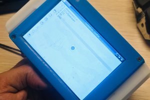
    First test was into the RTL-SDR plugged into an Android tablet, pulling in Radio China in the 13MHz band. Probably wasn't transmitted from China, but hey, it sounds impressive.

    Second test was with a laptop, the RTL-SDR, and SDRSharp. Here's a Croatian radio amateur on the 20m band.

    The antenna in both cases was a longwire.

    So there you are. Prototype built, and demonstrated as working.

  • Components ordered

    Jenny List11/24/2015 at 15:16 0 comments

    A big component order went in yesterday, and with it went the extra bits for this project. Still a week or two to wait for the PCBs though, so no hardware to show as yet.

  • Project files up on GitHub

    Jenny List11/20/2015 at 14:57 0 comments

    A few more aesthetic PCB tweaks, and the project is up on GitHub, here. Eagle files, Gerbers, and a BoM. I've licenced it under the Solderpad Hardware licence.

  • PCB image update

    Jenny List11/19/2015 at 09:49 0 comments

    I've updated the gallery with an image of the PCB I sent to OSH Park. A minor component change - a Panasonic B electrolytic rather than an A - and some careful track manipulation to make better groundplane coverage.

    OSH Park tell me my board will be made on the 20th. Then it has to make it to the UK. So now, we wait.

  • First day

    Jenny List11/18/2015 at 17:56 0 comments

    Decided to do a square inch entry with an idea that I've had floating around for a while. A bit of work with Eagle and I have a PCB designed, a bit of work with a browser & spreadsheet & I have a costed BoM.

    I've tried to design it with hand-assembly in mind, so the components aren't as tiny as they could be. I'm sure without that constraint it could fit in a 1/4" square :)

    The basic design is tried-and-tested, it's the mixer from my Pi-HF direct conversion receiver kit for the Raspberry Pi. (You can buy a Pi-HF here!) It's using a VHC4053 rather than the HC you might expect because while the HC will handle HF frequencies on its input I find most of them top out around 70MHz and anyway the VHC gives better performance at HF. We need our mixer to be happy with an 80MHz output, the VHC goes up to 120MHz.

    The Ethernet transformer is being used as a cheap way to get an RF transformer, and conveniently there are two in the package.

    Next step: send off for some PCB prototypes & build a working model.

    All the files will be put up under a suitable open hardware licence when finalised so you can build your own. I'll also be selling it as a kit, if it performs well.

View all 8 project logs

Enjoy this project?

Share

Discussions

pl.clay wrote 05/06/2021 at 23:51 point

Did the kit ever happen?

  Are you sure? yes | no

zakqwy wrote 01/18/2016 at 14:17 point

Quick question on your PCB--I noticed that you were able to get structural support slots for the USB plug to work from OSHpark. I had issues with this recently--can you give me a few pointers on your footprint design? Oval shaped with a single hole in the middle, or several holes in a line?

  Are you sure? yes | no

Jenny List wrote 01/18/2016 at 15:10 point

I'd love to give some 1337 PCB wizard answer, but I just used a footprint for the USB plug that came ISTR from the Sparkfun library. (Either that or the stock libraries, I'd have to check, but am not in front of Eagle)

It gave several warnings on the design rule check, indicating that it uses a row of overlapping holes.

  Are you sure? yes | no

zakqwy wrote 01/18/2016 at 15:27 point

Sounds good--I'll give that a try in my next board iteration. Thanks!

  Are you sure? yes | no

[deleted]

[this comment has been deleted]

Jenny List wrote 01/17/2016 at 09:53 point

The schematic exported from EAGLE is probably rather misleading. EAGLE's 4053 model includes an implicit Vcc, Vee, and ground connection that doesn't appear on the symbol.

Have a look at the PCB layout and you'll see that those pins are grounded.

  Are you sure? yes | no

Jenny List wrote 01/17/2016 at 14:19 point

I can't reply to your answer from further down the tree for some reason.. Just one thing - which type of 4053 are you using? It's important to use a VHC4053, lesser 4053s may not be quick enough. An HC4053 might work, but will not give good performance in this application.

Was your query about the 5v 50MHz oscillator a query about sourcing the component? In which case Mouser have them. However I would expect other suppliers, RS, CPC, Digikey etc to have them too.

  Are you sure? yes | no

dave wrote 01/10/2016 at 23:38 point

Will the boards be available to buy, or kits?

  Are you sure? yes | no

Jenny List wrote 01/11/2016 at 15:31 point

Yes, I'll be making this available as a kit, keep an eye on http://shop.languagespy.com/.

Currently waiting for prototype v1.2 boards to arrive, if I kit something up I want it to be as good as I can make it.

  Are you sure? yes | no

Eric Hertz wrote 12/11/2015 at 10:00 point

Always wondered how upconverters worked, cool. So, it basically takes the input signal and multiplies it by 1 then by -1 at 50MHz. Simple! Nice use for ethernet transformers, too

  Are you sure? yes | no

Jenny List wrote 12/11/2015 at 11:08 point

Hi, and thanks for your comment!

It's an addition or subtraction not a multiplication, so for example if I take a 10MHz signal and mix it with my 50MHz oscillator I can tap off either 40 or 60MHz results. There are multipliers used in radio, typically to filter off a multiple of a crystal-generated frequency, but they are very non-linear and not suitable at all for this work.

I'm happy winding my own transformers but realise not everyone else is. Made-for-RF transformers aren't cheap. Then I noticed that ethernet transformers have the specs, and are cheap. They probably aren't the perfect RF transformer for all circumstances because they have a common-mode rejection transformer built in and they're only available in one impedance, but they're a good enough component for this job, and a happy circumstance of one that doesn't cost much.

  Are you sure? yes | no

Martin wrote 02/22/2016 at 09:58 point

In the time domain (as voltage) it is a multiplication. That gives the sums and differences in the frequency domain.

  Are you sure? yes | no

Jenny List wrote 02/22/2016 at 10:34 point

@Martin: A voltage multiplication? Really? 

In the time domain it's a voltage addition, surely? Apply a 'scope to any mixer and you'll see the result bears that out.

  Are you sure? yes | no

Blecky wrote 12/07/2015 at 01:26 point

[verified: no design files missing]

  Are you sure? yes | no

alpha_ninja wrote 12/02/2015 at 00:41 point

This is your one-week reminder to upload design documents: https://hackaday.io/project/7813-the-square-inch-project/log/28566-design-deadline

  Are you sure? yes | no

Similar Projects

Does this project spark your interest?

Become a member to follow this project and never miss any updates