Jenny List
-
Kit progress so far
02/22/2016 at 08:05 • 0 commentsThis project has not seen the progress you might expect of late, as some other things have taken my attention and Chinese New Year has intervened as it always does.
My updated boards arrived from OSH Park - https://oshpark.com/shared_projects/Vfd9X8z1 - and I built a second prototype. I'm writing this up somewhere else too, so a lot more tests were done.
As I've said, I'll make this available as a kit in time. Probably before summer. It's sometimes a little difficult, managing the flow of new products in a small kit business, you have to sell a certain number of kits to be able to invest in new ones and there are one or two other products in the queue. So please, everyone, buy more kits! :) http://shop.languagespy.com/
One thing I face making a kit from this is the cost of those SMA connectors. I can buy high-quality ones at a price, or I can buy cheap ones of dubious quality from your favourite Chinese online goodies bazaar. I am concerned that my connectors be of decent quality, I have seen some awful build quality masquerading as connectors and I don't want to unload that on my customers. It is definitely the case that not all SMA connectors are equal.
So watch this space, the kit *is* coming.
-
Waiting for PCBs... Again.
01/10/2016 at 22:33 • 0 commentsAll quiet, waiting for those PCBs to arrive. Christmas always adds two weeks to any delivery.
-
Rev. 1.2 PCB update
12/20/2015 at 21:50 • 0 commentsA small PCB update, the SMAs now have a more appropriate orientation with centre pins on top of the board. Also osc decoupling cap moved slightly.
-
Prototype built, and running
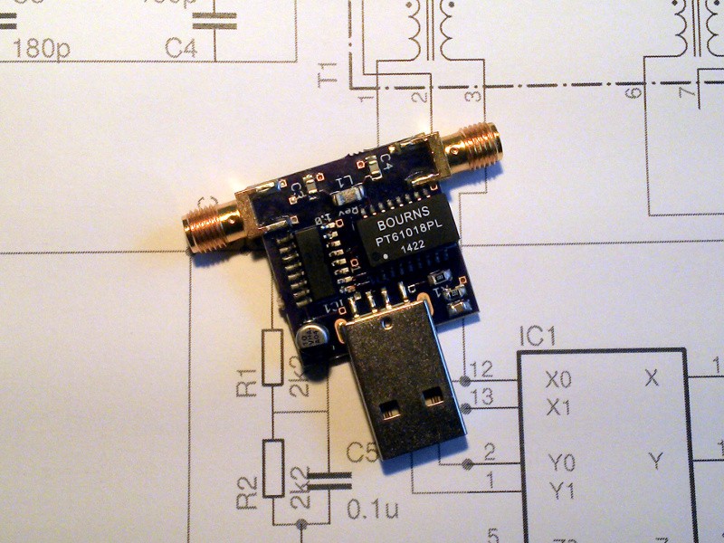
12/09/2015 at 15:21 • 0 commentsThe envelope from OSH Park arrived this morning with the PCBs in it, so I put in half an hour to build a prototype board.
![]()
It's not really a challenging build, I was concerned that there wouldn't be enough space between transformer and USB connector but in practice that worry was unfounded. All the chip components first, then the mixer IC, then the transformer, the electrolytic, the oscillator, and finally the connectors. Lots of flux all over everything, but a quick brush with a bit of solvent cleaner dealt with that.
Visual check OK, no shorts, power it up and run the tests to demonstrate it works as required by the competition rules.
First test was into the RTL-SDR plugged into an Android tablet, pulling in Radio China in the 13MHz band. Probably wasn't transmitted from China, but hey, it sounds impressive.
Second test was with a laptop, the RTL-SDR, and SDRSharp. Here's a Croatian radio amateur on the 20m band.
The antenna in both cases was a longwire.
So there you are. Prototype built, and demonstrated as working.
-
Components ordered
11/24/2015 at 15:16 • 0 commentsA big component order went in yesterday, and with it went the extra bits for this project. Still a week or two to wait for the PCBs though, so no hardware to show as yet.
-
Project files up on GitHub
11/20/2015 at 14:57 • 0 commentsA few more aesthetic PCB tweaks, and the project is up on GitHub, here. Eagle files, Gerbers, and a BoM. I've licenced it under the Solderpad Hardware licence.
-
PCB image update
11/19/2015 at 09:49 • 0 commentsI've updated the gallery with an image of the PCB I sent to OSH Park. A minor component change - a Panasonic B electrolytic rather than an A - and some careful track manipulation to make better groundplane coverage.
OSH Park tell me my board will be made on the 20th. Then it has to make it to the UK. So now, we wait.
-
First day
11/18/2015 at 17:56 • 0 commentsDecided to do a square inch entry with an idea that I've had floating around for a while. A bit of work with Eagle and I have a PCB designed, a bit of work with a browser & spreadsheet & I have a costed BoM.
I've tried to design it with hand-assembly in mind, so the components aren't as tiny as they could be. I'm sure without that constraint it could fit in a 1/4" square :)
The basic design is tried-and-tested, it's the mixer from my Pi-HF direct conversion receiver kit for the Raspberry Pi. (You can buy a Pi-HF here!) It's using a VHC4053 rather than the HC you might expect because while the HC will handle HF frequencies on its input I find most of them top out around 70MHz and anyway the VHC gives better performance at HF. We need our mixer to be happy with an 80MHz output, the VHC goes up to 120MHz.
The Ethernet transformer is being used as a cheap way to get an RF transformer, and conveniently there are two in the package.
Next step: send off for some PCB prototypes & build a working model.
All the files will be put up under a suitable open hardware licence when finalised so you can build your own. I'll also be selling it as a kit, if it performs well.
HF receive converter for RTL-SDRs and similar
Converts 0 - 30 MHz up to 50 - 80 MHz. Allows HF(shortwave) reception on RTL-SDRs and the like. A square inch project entry