-
Yup, I made another revision
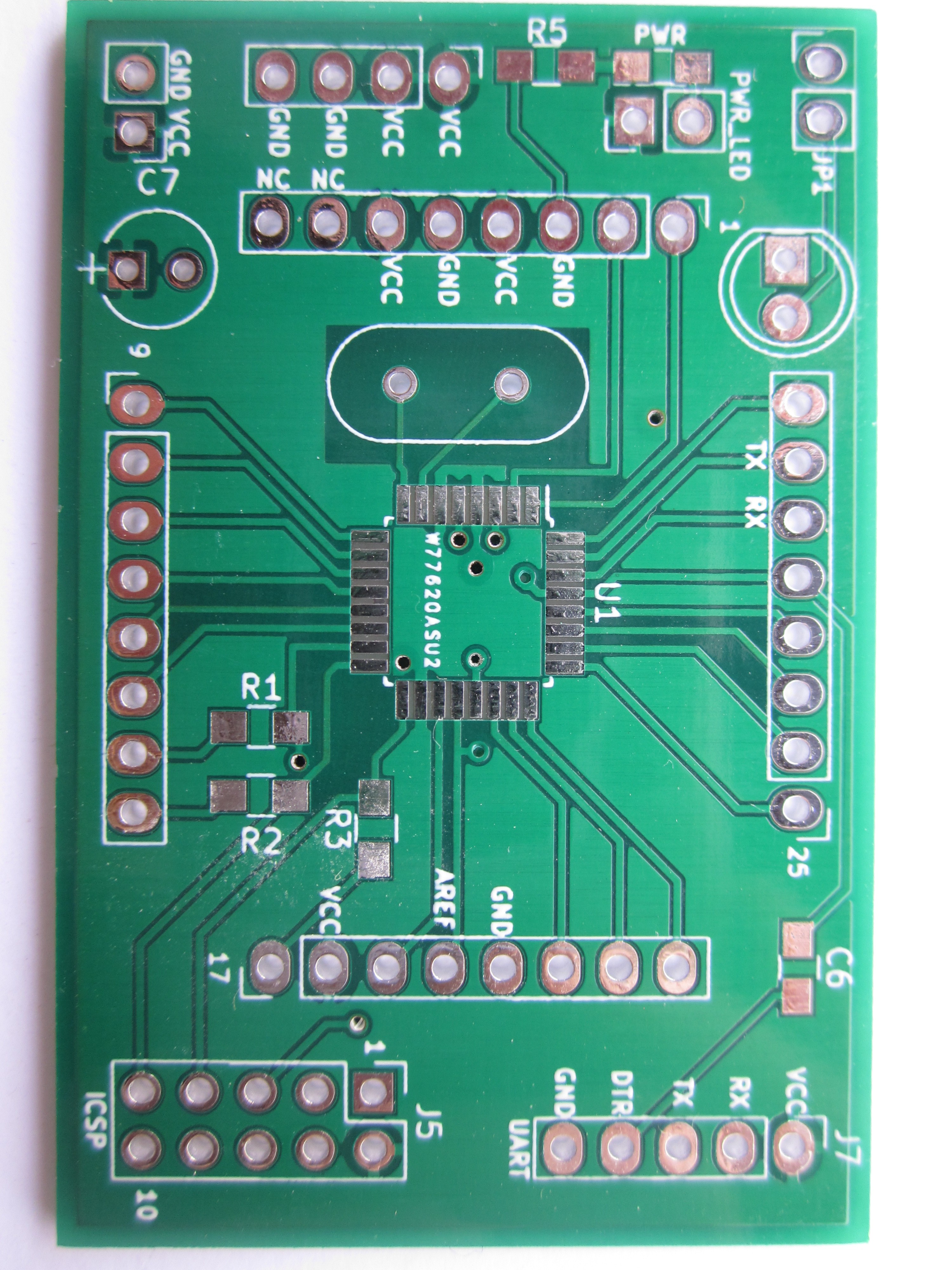
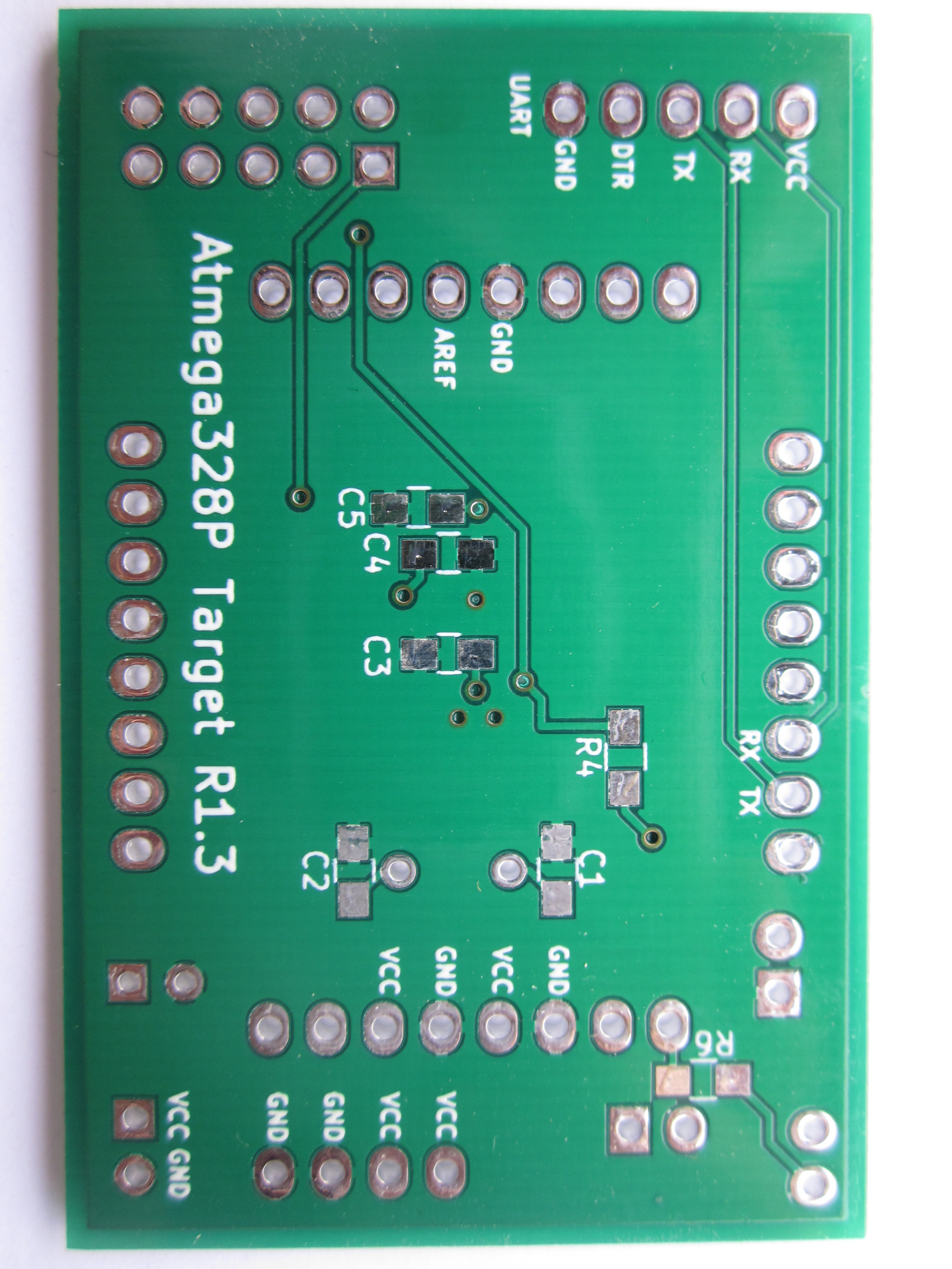
01/08/2019 at 20:42 • 0 commentsI went ahead and made yet another revision of the board,1.3.
Changes made:
Added a plane for VCC
Added a jumper for the power LED (useful for low-power projects)
Made many pin header pads larger for easier soldering
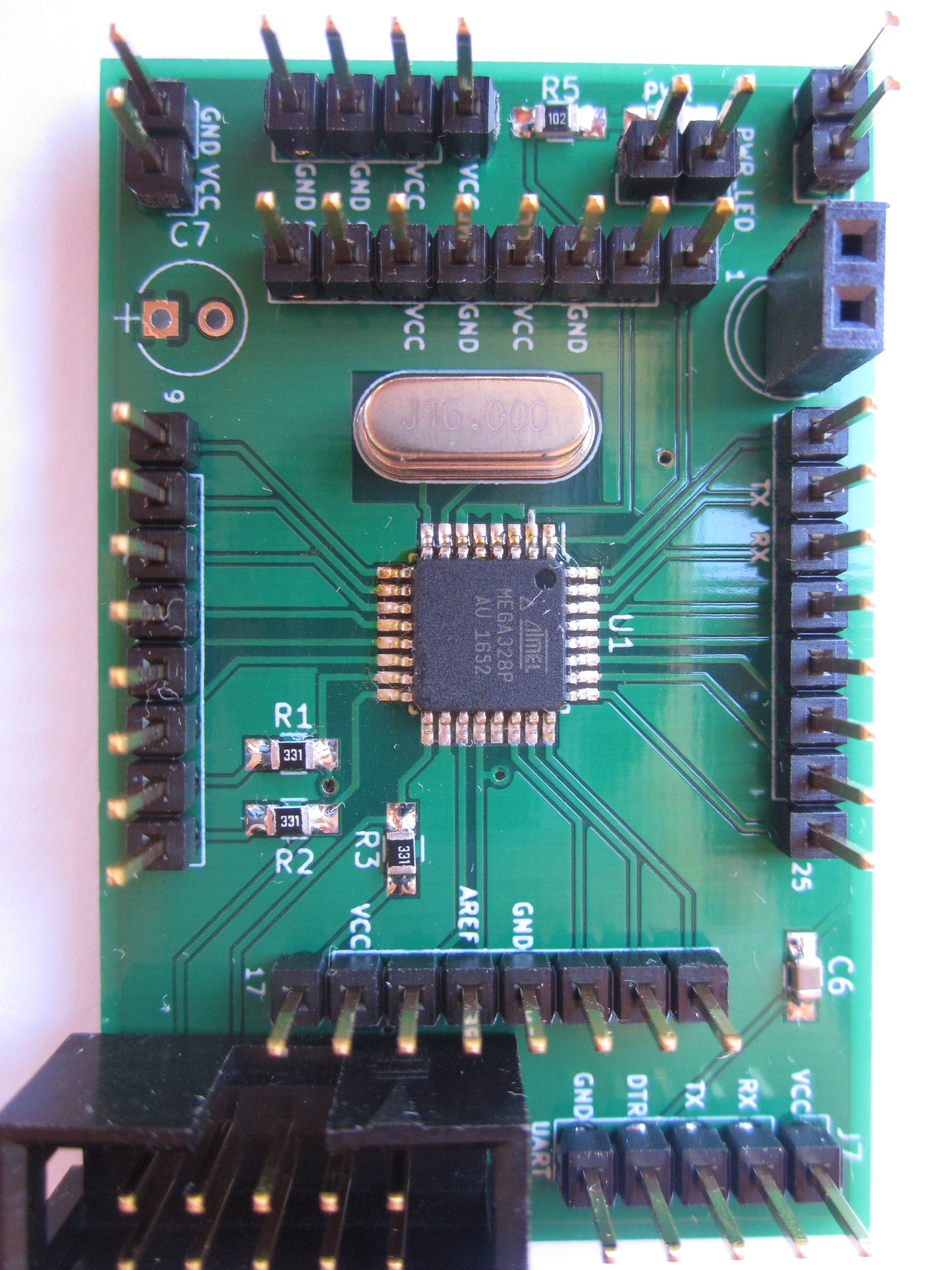
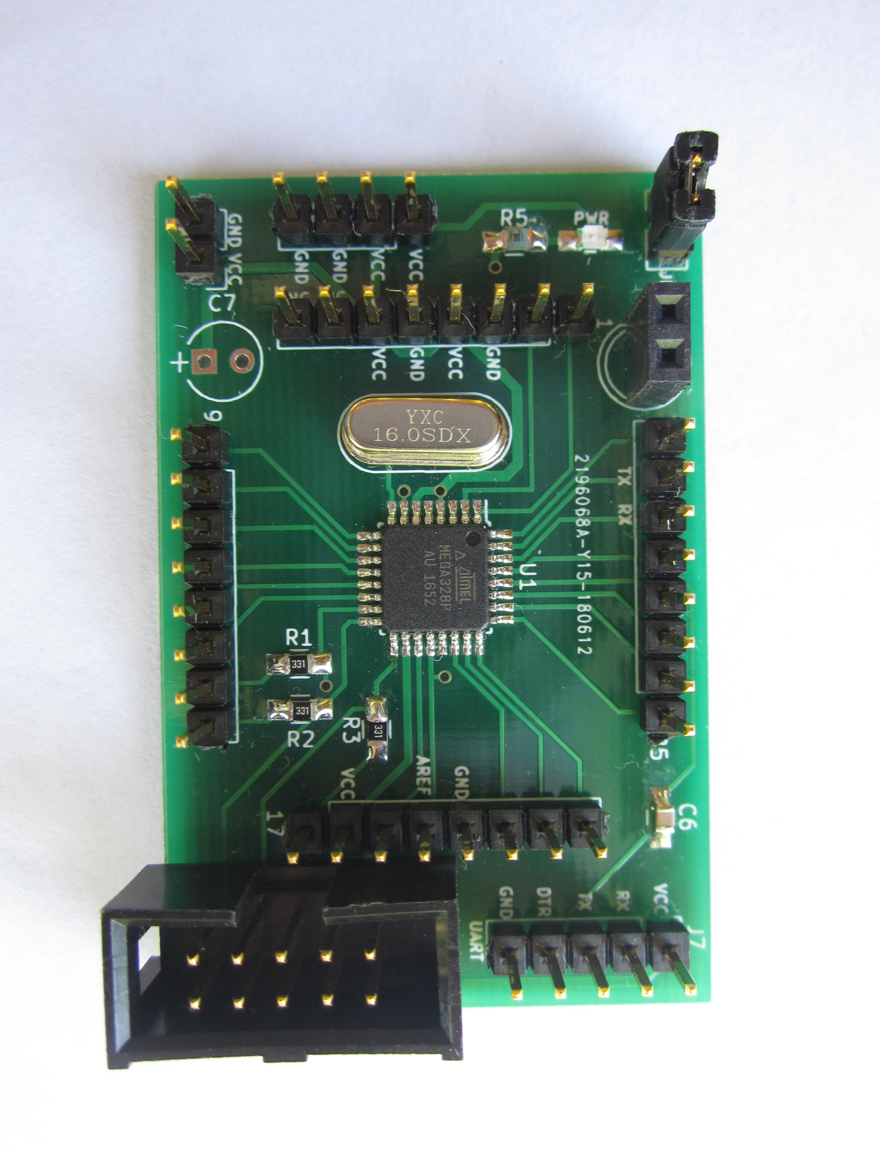
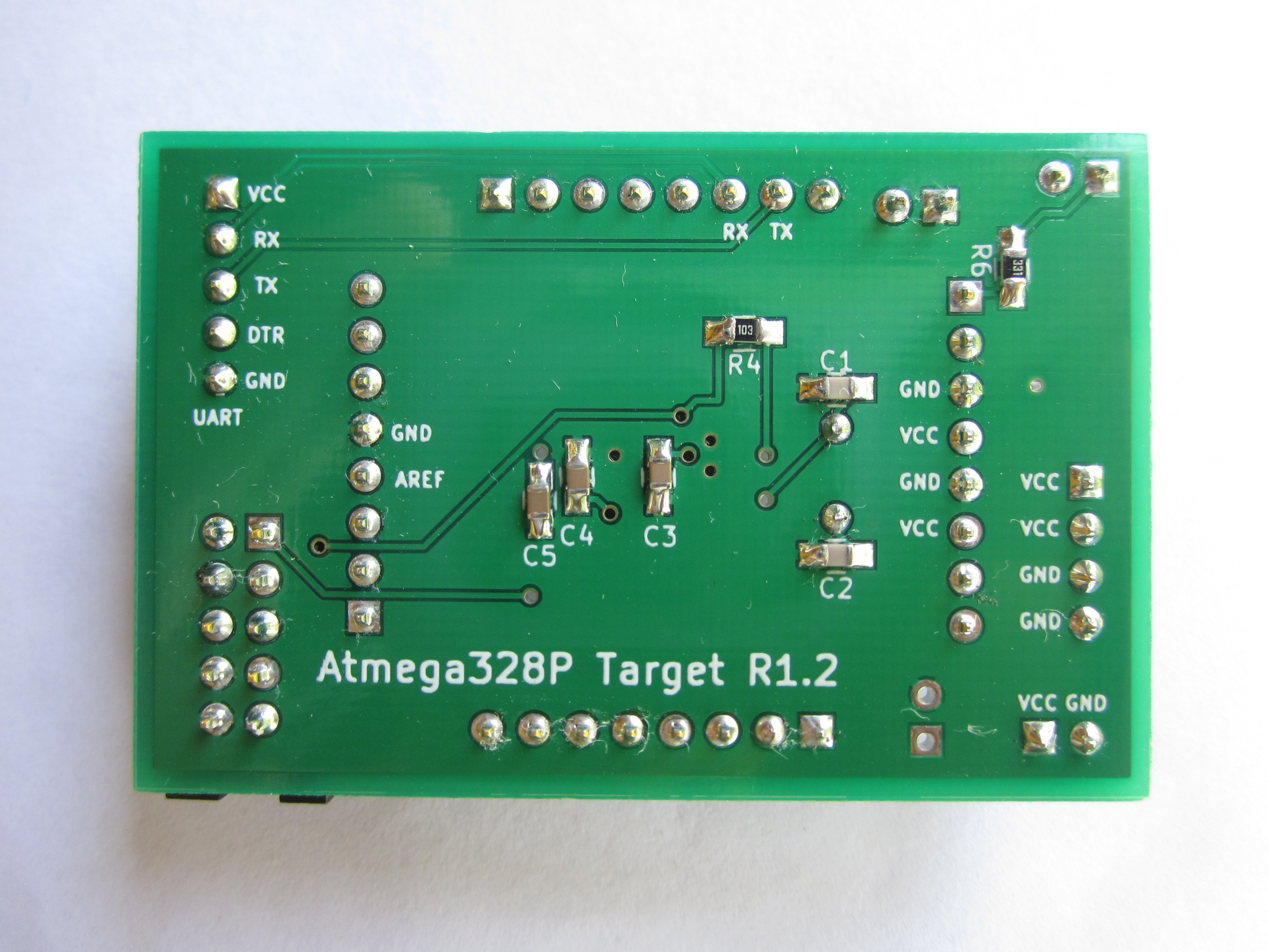
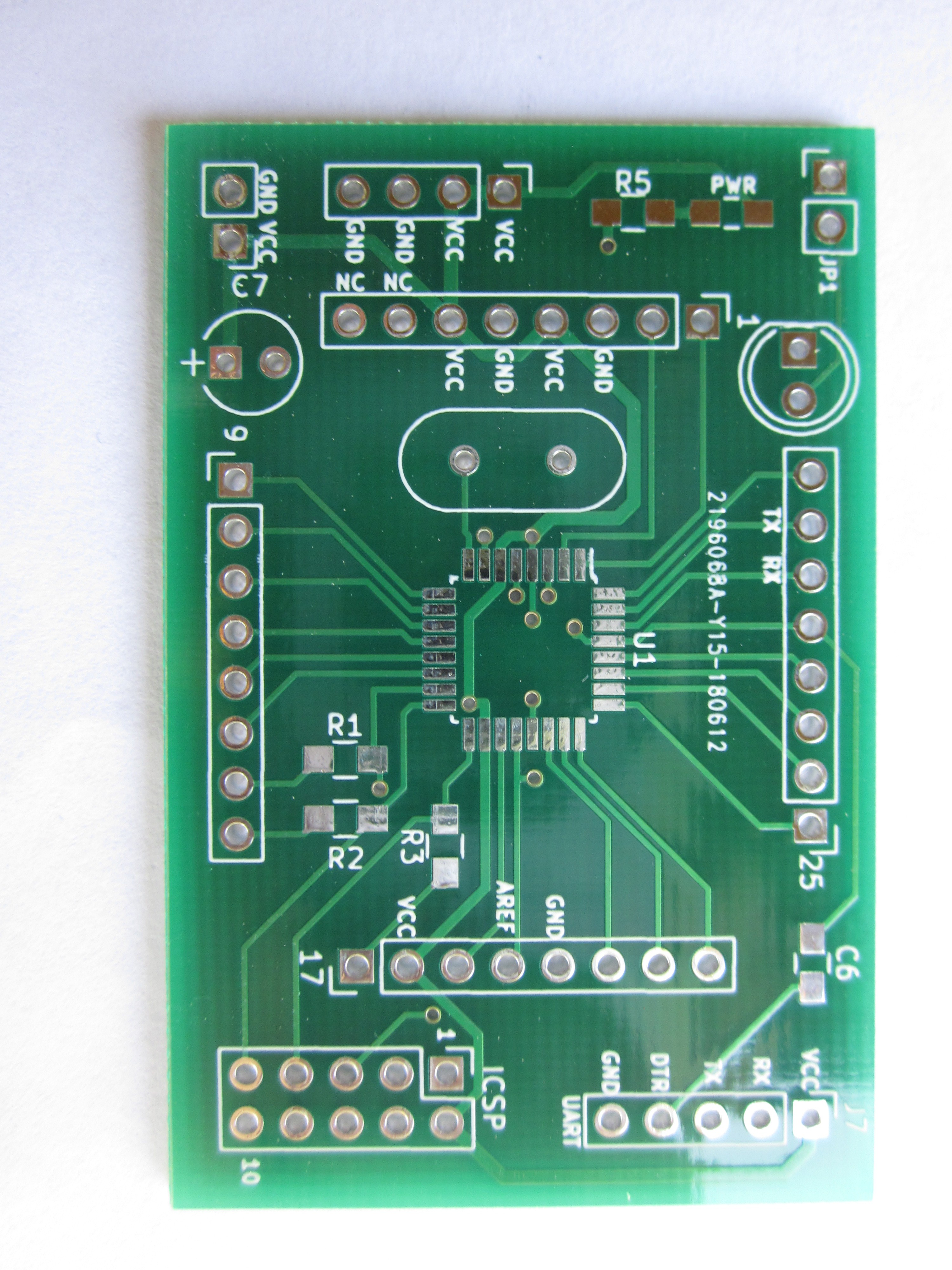
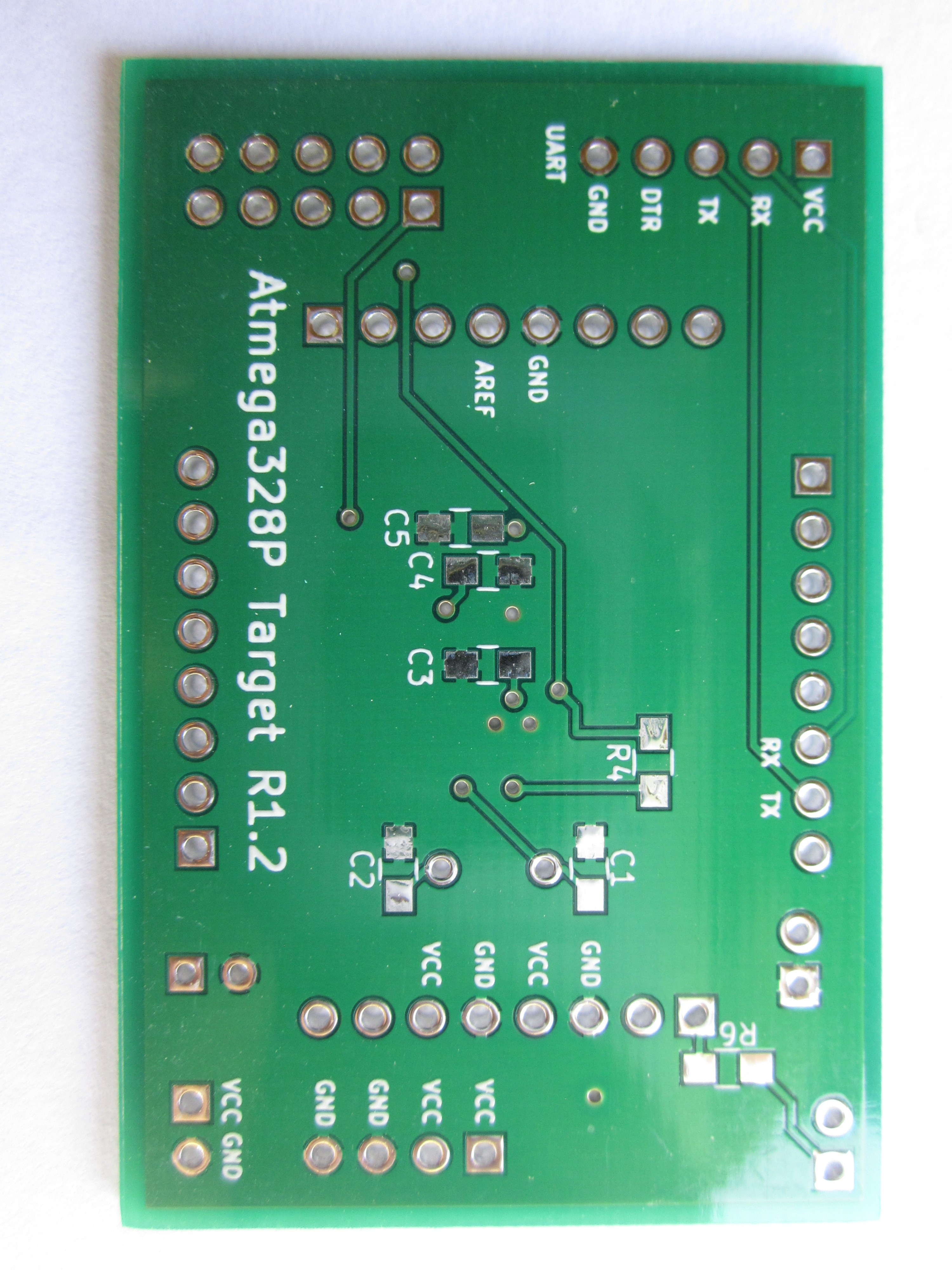
It's looking really polished now. The only downside is by adding a power(VCC) plane it does take some additional dwel time with the soldering iron to solder some of the pins/pads (very noticeable when I soldered the power pins on the Atmega328P, but not terrible.)
I did the two-part technique for soldering on the Atmega328P; first soldering the chip on with and iron and then adding additional flux again and going over with with my hot air station. As Dave would say, looks like a bought one.
![]()
![]()
![]()
-
Changes that I would make in a future revision
08/29/2018 at 14:27 • 0 commentsOverall the board as served me quite well, but there is almost always room for improvement. Below are a few changes that would make if I get around to making another revision:
Add a jumper in series to the power LED. When it comes to working with low-power projects and running it off of batteries, the little bitty LED can consume quite a bit of power compared to everything else. One could simply not solder in the LED, but this would be a more flexible solution.
Simply do a power plane for the top layer. A thing that I've ran into when designing the board was having trouble fitting in nice thick power traces for everything. It's perhaps a bit overkill, but why not?
Possibly squeeze in an LDR. I've found it quite useful on my 1284P board, might been worth trying to squeeze it in.
-
Boards arrived and so far everything has went well.
07/11/2018 at 15:11 • 0 commentsThe Saturday before last my PCBs arrived from JLCPCB. I got the joy of getting out my soldering station and assembling everything. It took me about an hour or so to get it assembled. It would really be nice to have a space for a dedicated bench vs having to invade to kitchen counters, but you can't have everything.
I plugged in my USBASP into the board and used avrdude to check that it could talk to the chip. Avrdude was able to read it without issue. FYI, I've learned that all surface-mount versions of the Atmega328P have kept full-swing oscillator support, the hardware revision that removed support for it was cancelled.
Again many thanks to all of you that liked my project that resulted in me getting the HaD prize seed funding to pay to get the boards made. I'm not currently employed (I do side jobs when I get the opportunity), so I have to watch my spending.
![]()
![]()
![]()
![]()
-
OK the board looks nice, but what is it useful for?
03/19/2018 at 16:38 • 0 commentsI've decided to post some code for various things I've done with the board such as driving a stepper and a servo.
If you happen to want to observe an MCU crash and have a revision 1.1 board made up, hook up a MG90s servo to the servo header. I've found it crashing in various interesting ways including inverting the duty cycle of the PWM signal. Even setting up the watchdog timer doesn't bring it back to sanity.
-
A convenient way to hook up a battery pack
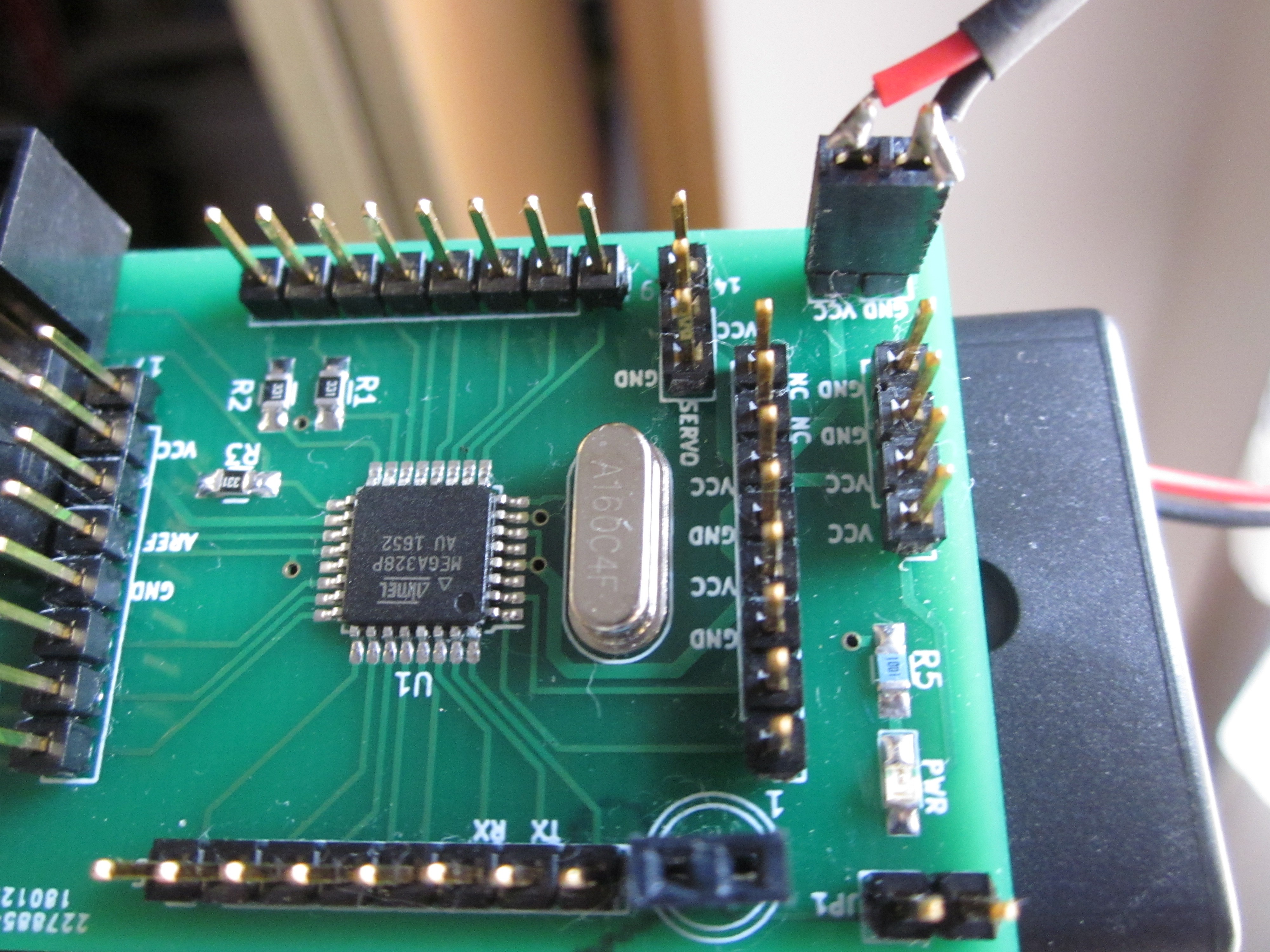
03/15/2018 at 14:36 • 0 commentsSome time ago I bought some 2 AA battery holders that were little over $1 USD for two. For the Atmega328P, the minimum operating voltage is 1.8V, allowing it to be run on 2 AAs. An important note is that according to the datasheet, you can't exactly run it at 20 MHz with 2.4-3V which is why I assembled a board using a 4MHz crystal.
I didn't want to permanently solder a battery holder to the board so I decided to solder a 2-pin .1" header to the wires of the battery holder, making a plug or sorts. On the board there is a 2-pin male header that of course has VCC and GND. I could have used a 2-pin female header on the board and just pushed the battery holder wires into that, but based on past experience the resulting connection tends to be iffy at best. A downside is that since there is no keying, you have to be careful not the plug it in backwards.
![]()
-
What features/design changes would you like to see in R1.2?
03/12/2018 at 21:48 • 0 commentsOf course not too long after I got my revision 1.1 board, I've made some changes to the board yet again (adding a DTR line for bootloader friendliness, removed the 3 pin servo header, and added an electrolytic cap to help further smooth the supply voltage.) That revision is being called 1.2 but I have yet to send that off to be made, so I have no qualms with modifying it further.
If anyone has any ideas be sure to comment below. Hitting the like button on the project would be much appreciated as I get $1 for every like as I entered it into the 2018 HAD prize.