danjovic
-
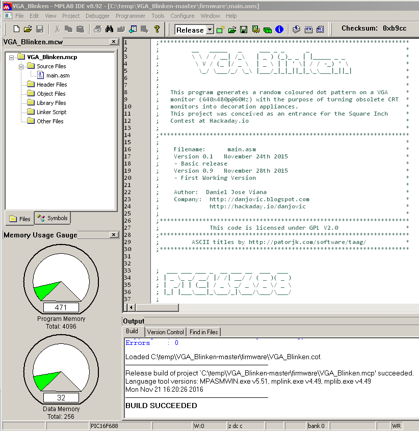
Entry for 1K contest
11/21/2016 at 18:28 • 1 commentI am recycling this project as an entry for the 1K contest. It takes only 471 words which considering 14 bit wide instructions will give us the equivalent to 824.25 bytes .
![]()
-
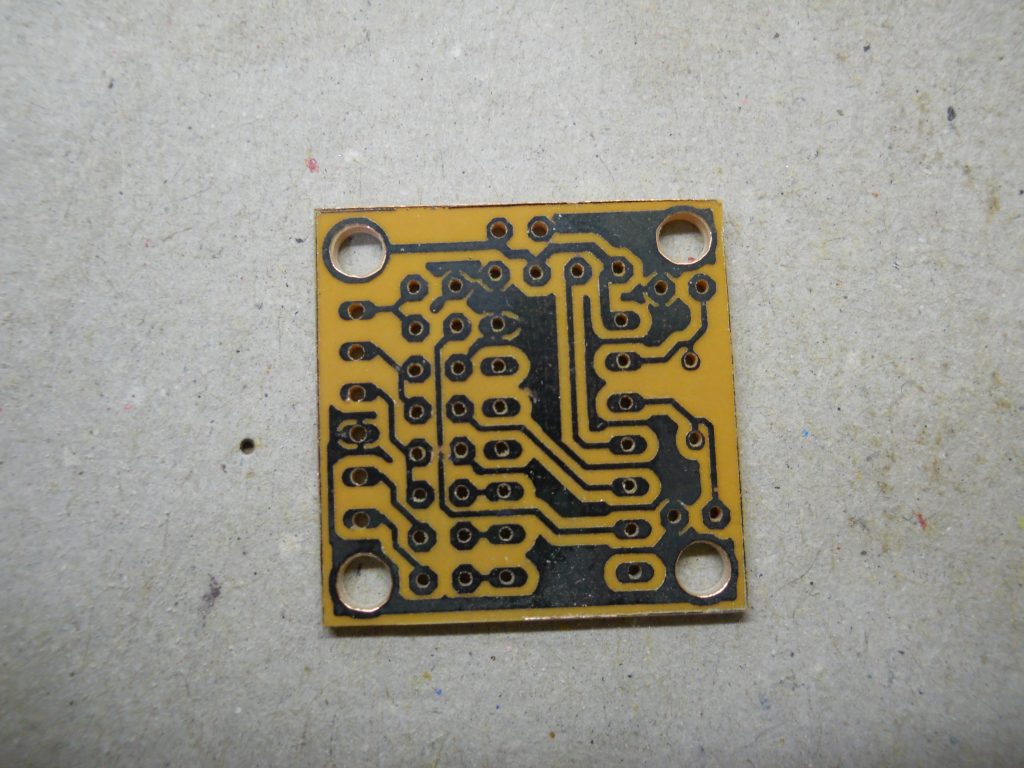
PCB assembled and working
11/29/2015 at 05:32 • 3 commentsThe PCB for this project is single sided, then I've decided to make it home.
![]()
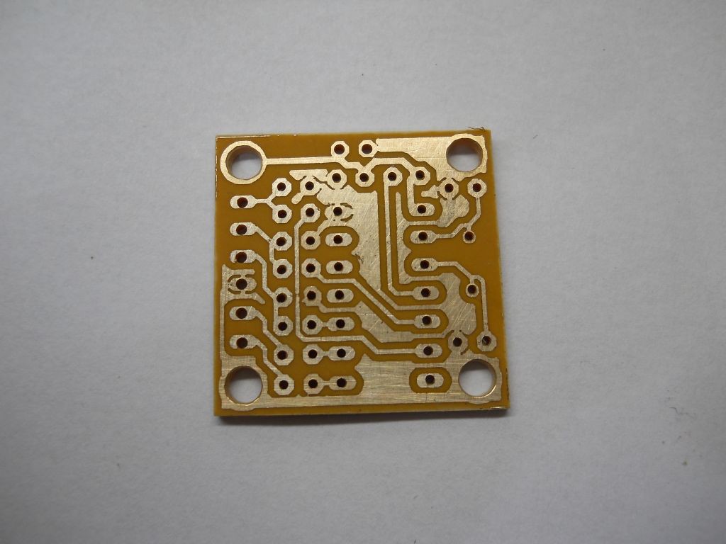
After silver bath.
![]()
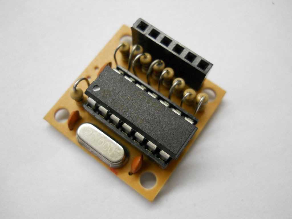
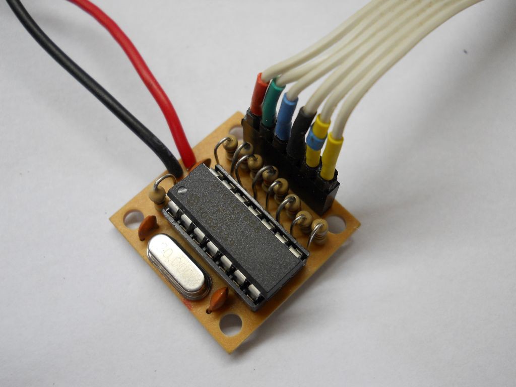
After assembly
![]()
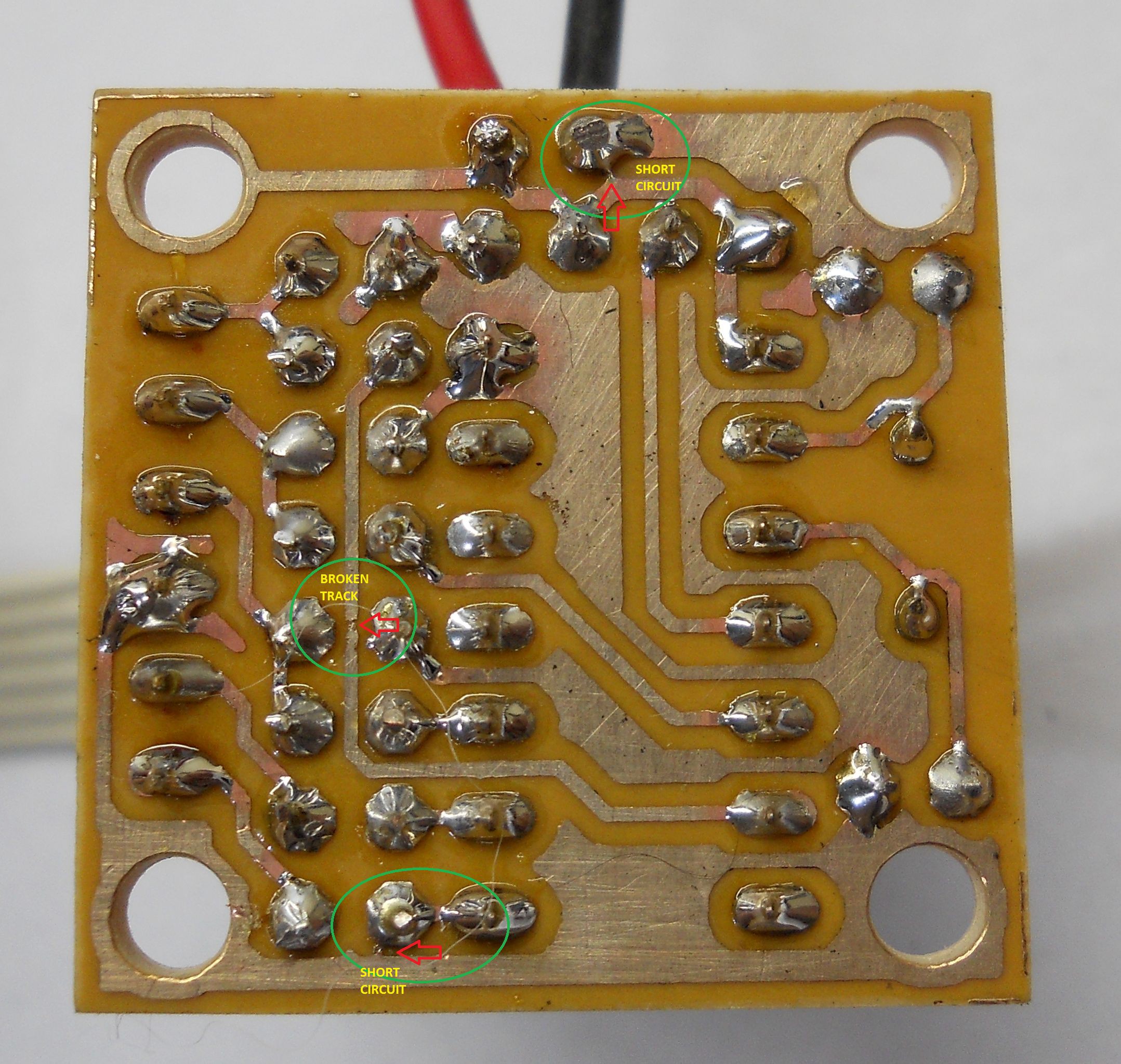
some defects were found and corrected.
![]()
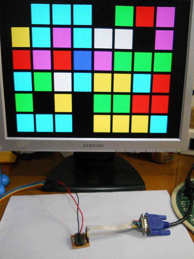
And now the circuit is working fine!
![]()
![]()
And here is a video
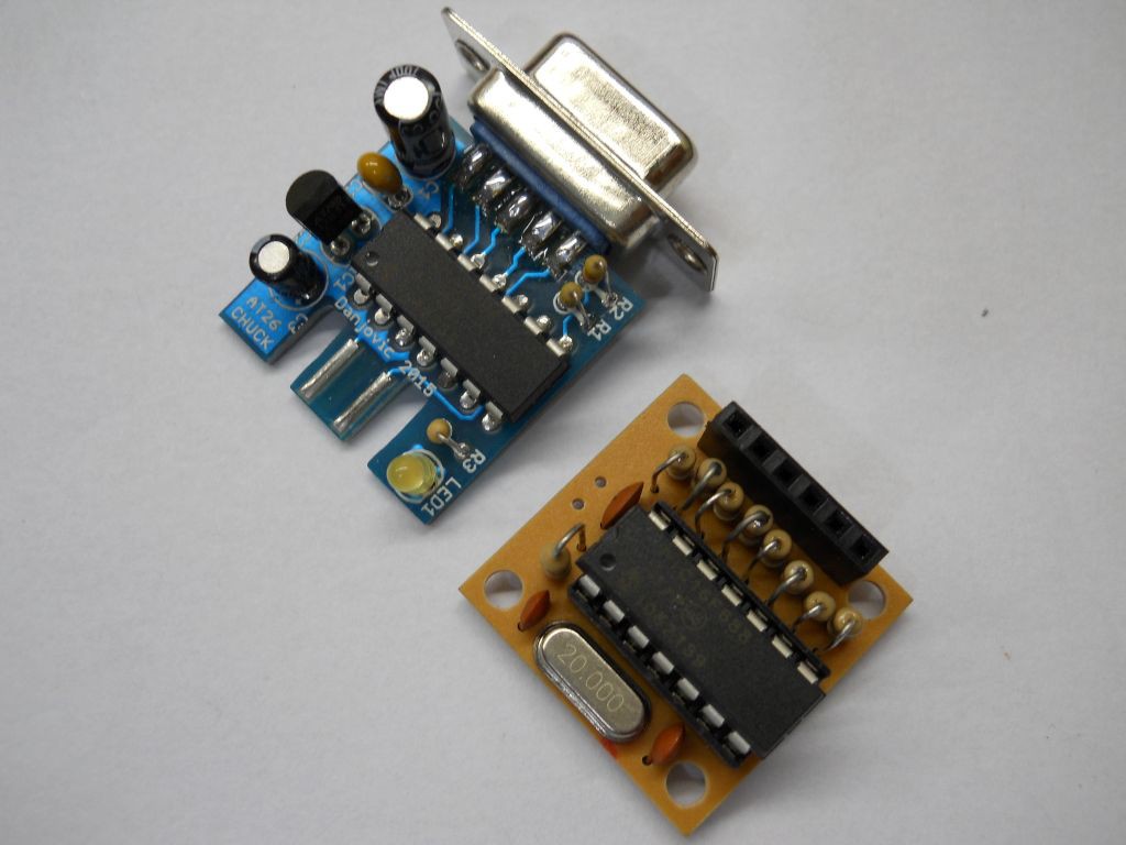
And now compared with #AT26-Chuck , another Through Hole project for #The Square Inch Project
![]()
-
It's alive, it's blinking!
11/28/2015 at 12:24 • 0 commentsFinally finished first working version. ?An enhancement was to make the interval between the blinkings be a random time between 0.36 and 0.63 seconds.
-
Rendering the grid of 'dots'
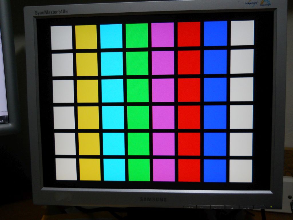
11/27/2015 at 01:08 • 0 commentsI've managed to render the grid of 8 x 6 'dots' on the screen whilst the pseudo random sequence generator is on the way.
![]()
-
Defining the timings
11/26/2015 at 00:11 • 0 commentsJust defined timing for each colour pattern as well as the quantity of 'color dots' on the screen.
Assuming that most CRT monitors have a 4:3 or 5:5 aspect ratio as well as the execution speed constraints, the amount of 'color dots' shall be 8 in horizontal and 6 in the vertical.
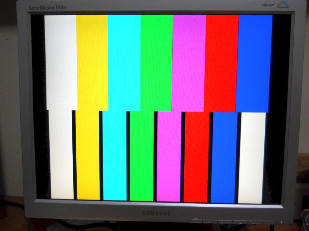
The ratio between color dots and spacing shall be 6:1 and the color dots shall be 12 cycles wide by 2 cycles of black screen.
In the picture below the lower part of the screen has stripes and intervals that correspond to the numbers presented above.
![]()
-
Code is cheap, show me the wires
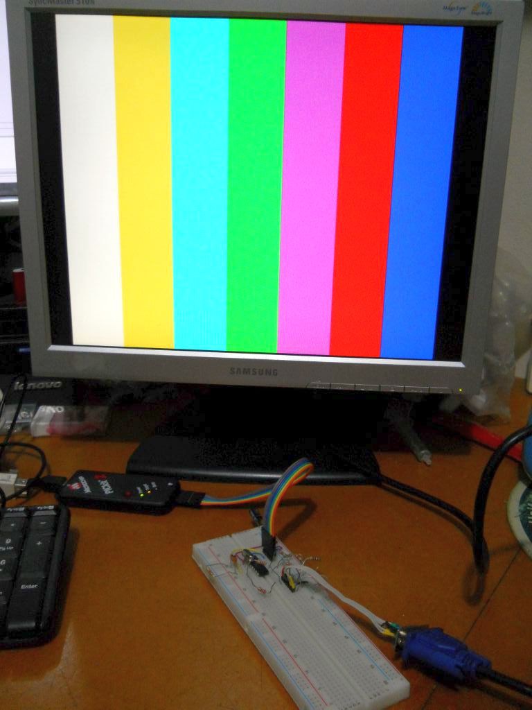
11/25/2015 at 00:26 • 0 commentsWell, continuing from the last log, here are the results. Each colour stripe takes exactly 16 cycles.
![]()
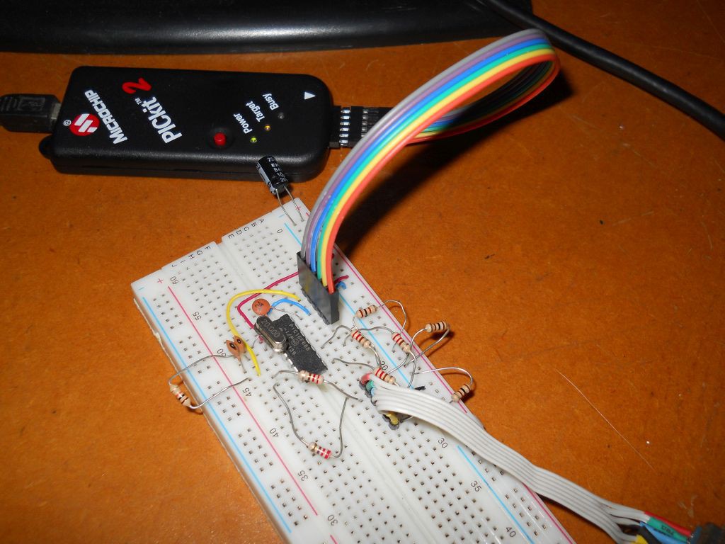
The circuit is assembled on a proto-board.
![]()
Next step is to turn this stripe pattern into a beautiful dot color matrix.
-
Generating video, one cycle at a time
11/25/2015 at 00:23 • 0 commentsThe base of the project is the cycle-by-cycle generation of VGA video signal borrowed from Tic Tac X, a previous project of mine.
A standard VGA frame (640x480@60Hz) has 525 lines of video. Each line takes 31.77us to happen.
When using a PIC running at 20MHz each instruction takes 200ns.
Divinding the numbers and rounding up to the next integer we have 159 cycles. Such amount of clock cycles shall be precisely counted in order to have a jitter free picture.
To form a frame you have to issue
- 2 lines front porch
- 2 lines vertical sync
- 25 lines back porch
- 8 lines top border
- 480 lines video
- 8 lines bottom border
The sum of it all gives exactly 525 lines or 83475 clock cycles
Considering that the back porch, top border and bottom border lines are all blank lines (1 hsync and black video after) we can rearrange the frame as:
- 2 lines vertical sync
- 33 lines back porch + top border
- 480 lines video
- 10 lines bottom border + front porch
The next trick is to split the 480 lines of visible video into 2 halves of 240 lines. Now that fits into an 8 bit counter:
- 2 lines vertical sync
- 33 lines back porch + top border
- 240 first half of lines video
- 240 second half of lines of video
- 10 lines bottom border + front porch
Next challenge was harder: Cascading loops! After finishing a loop (for example between the two halves of the visible we must load again a new value on the counter and it takes 2 instructions. The problem is that we have only one cycle time free that is caused by the skip of the 'goto' instruction that close the loop. I have spent some time trying to figure out a solution until it was given me by the mindset I got after TRIZ training: Use of 'preliminary action' as well as 'the other way out': I've inverted the order of the loading of a new value on the W register prior to test if the loop reached zero. Then if there is still more iterations this value is not used, otherwise I only spend 1 instruction time to save the pre-loaded value on the register used for counting.
The last problem is on the frame loop. I still have only one spare cycle and I need 2 for the 'goto' instruction that closes the loop.
The solution is philosophically similar: The last line was not called from a loop, so I do not have to test for the end of the loop (with decfsz) thus saving one instruction time that I need to jump again to the beginning of the loop.
(full explanation - in portuguese - here)
My final VGA frame is then:
- 2 lines vertical sync
- 33 lines back porch + top border
- 240 first half of lines video
- 240 second half of lines of video
- 9 lines bottom border + front porch
- 1 line bottom border + front porch
Talk is cheap, show me the code
Well, there it goes:
; ** Render a VGA Frame DO_VGA: movlw 2 ; Initialize amount of Vsync Lines VGA_Frame: movwf Conta Vsync_loop: call Vsync_line movlw .33 ; amount of lines for next loop. Was placed here to decfsz Conta,f ; equalize timing of all loops that make the frame goto Vsync_loop ; each loop takes exactly 8 cycles + call time ; at 20Mhz we have 159 cycles per VGA line (31.8us) VBackPorch: movwf Conta ; 25lines backporch plus 8 lines top border VBackPorch_Loop: call Blank_line movlw .240 ; first half of vilible lines decfsz Conta,f goto VBackPorch_Loop First_half: movwf Conta ; 240 lines VFirst_Visible_Loop: call Visible_line movlw .240 ; second half of vilible lines decfsz Conta,f goto VFirst_Visible_Loop Second_half: movwf Conta ; 240 lines VSecond_Visible_Loop: call Visible_line movlw .9 ; last 10 blank lines minus one decfsz Conta,f goto VSecond_Visible_Loop VFront_Porch movwf Conta ; 8 lines bottom plus 2 frontporch VFrontPorch_Loop: ; minus one to equalize timing call Blank_line movlw .2 ; dummy decfsz Conta,f goto VFrontPorch_Loop nop ; dummy for equalize timing call Blank_line ; last is called outside a loop movlw .2 goto VGA_Frame ; -
Generating video with correct amplitude and output impedance
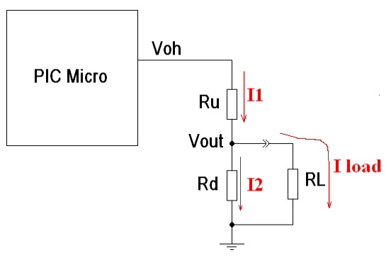
11/24/2015 at 02:26 • 0 commentsFor generating the video signals for this project we are going to use simple voltage dividers to provide the correct amplitude and output impedance.
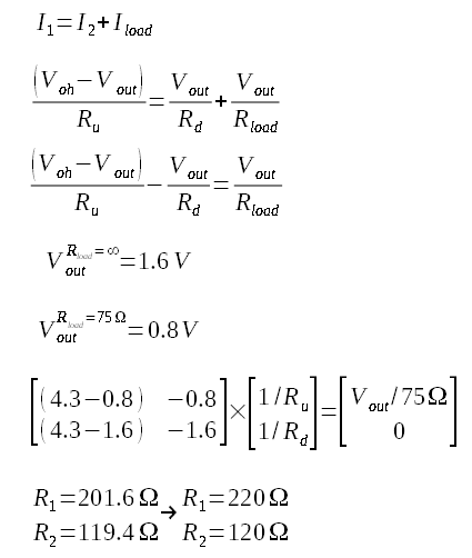
To calculate such values we should start by analyzing the voltages and currents involved.![]()
We are considering signals with a peak voltage of 0.8Volts with a 75 Ohms load because this is the amplitude of the video portion of a standard 1Vpp composite video signal (being the 0.2Volts below zero the amplitude of the sync tip). Without any load the peak amplitude of the video shall be twice that value (1.6V)
On the calculation we must also consider the output voltage of the microcontroller which is typically below Vcc.![]()
After the calculation we came close to two standard resistor values.