John Schuch
-
Log 3 - The Mini Controller.
04/23/2018 at 07:49 • 0 comments![]()
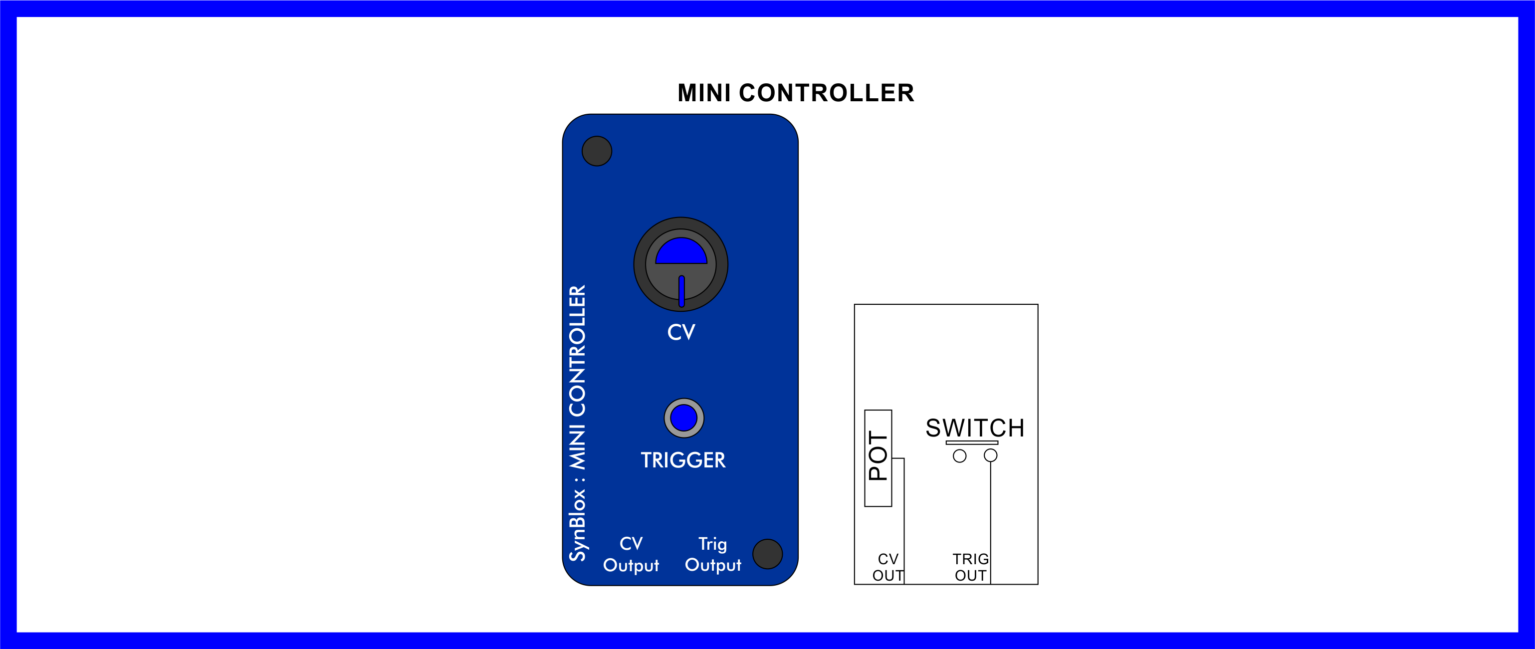
The Mini Controller provides the two basic control signals used by the modular synth; A variable voltage that would likely be used to set the pitch of a voltage controlled oscillator, and a trigger used to initiate envelopes, sequences, or any number of things.
It would be very easy to presume that all we need is a potentiometer set up as a voltage divider to provide the Control Voltage (CV), and a simple push button to create the trigger. If only things were that easy.
The pot for a variable voltage is fine, but we have no idea what an end user is going to plug this control signal into. More importantly, the load of whatever they are going to use. This unpredictable load means that we can not predict the output of the controller.
As for the trigger, if all we wanted to do was gate an audio signal, or trigger an envelope generator, a simple push button would probably work fine. The issue is if the user wants to plug this trigger source into a sequencer, or some other logic based device. For a sequencer, any electrical bounce in the switch is likely to send it to some random state, rather than the next step.
![]()
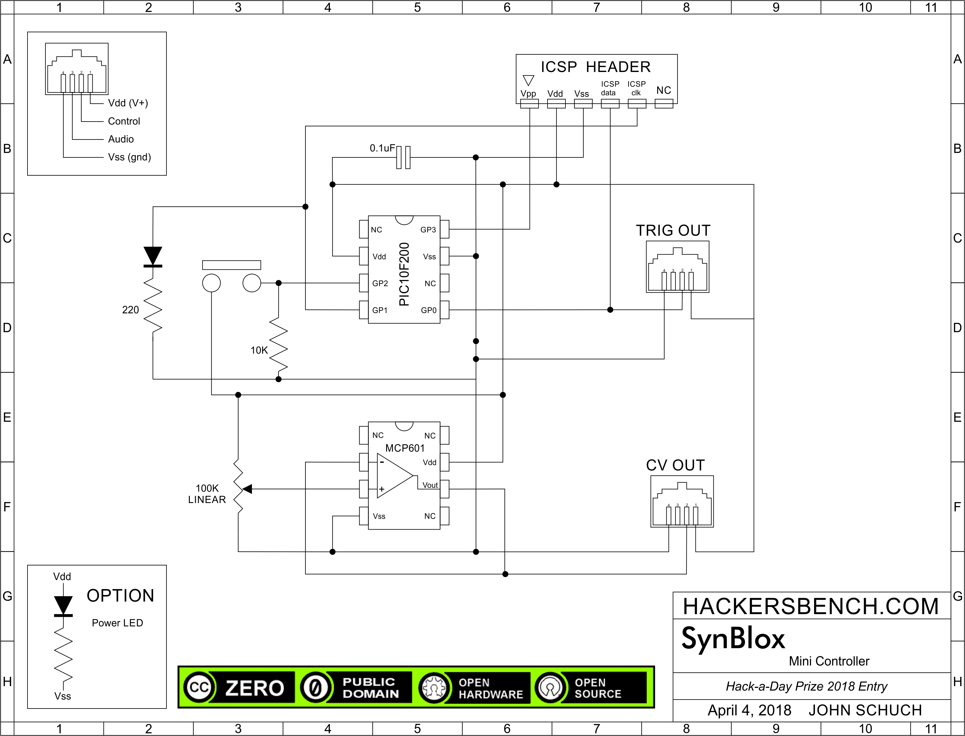
The lower half of the schematic is the control voltage circuit. You can see we have a 100K pot set up as a voltage divider as you would expect, but now we feed it into a buffer. The MCP601 op-amp is set up as a voltage follower. That is, whatever voltage level is presented to the non-inverting input will be sent to the output. But the input impedance of the op-amp is very high and will not change with changes in output load, so the voltage level generated by the pot will remain stable and predictable.
The upper half of the schematic is our trigger circuit. There are a LOT of ways to debounce a push button switch, and this is my favorite. A PIC10F200 is dirt cheap, and using software to debounce the switch give us all sorts of variability and control. In this circuit we're going for the simplest application; just debounce the switch and send the output on it's way.
The code to do this is so small I'm going to include it right here ...
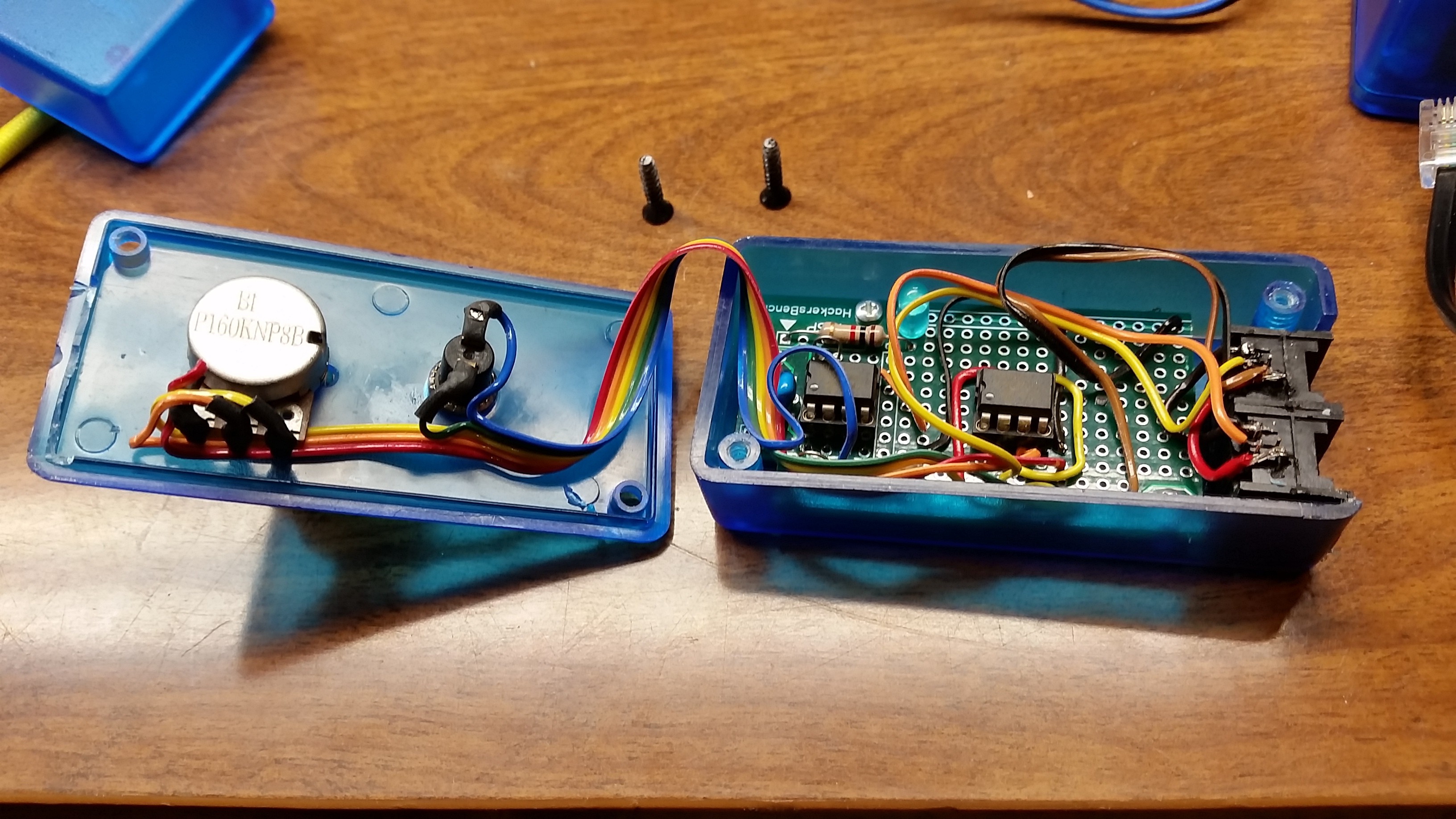
/**************************************************************************
 * File:   debounce.c
 * Author: John Schuch
 * File Version : 1.0
 * Created on April 14, 2018, 3:00 PM
 *
 * This software is released as PUBLIC DOMAIN. No rights reserved
 *
 * ************************************************************************
 *  Target           : PIC10F200
 *  Compiler         : MPLAB X v3.45 (free mode)
 *  Additional files : NONE
 *
 *  Description :   Provides debounce of the pushbutton on the SynBlox
 *                  mini controller, part of my submission to the 2018
 *                  Hackaday Prize contest.
 *
 *  Pins :  PIN 1 : N/C
 *          PIN 2 : Vdd
 *          PIN 3 : GP2 - pushbutton input, 10K pull up
 *          PIN 4 : GP1 (ICSP clk) output, indicator LED
 *          PIN 5 : GP0 (ICSP data) Module trigger output
 *          PIN 6 : N/C
 *          PIN 7 : Vss
 *          PIN 8 : GP3 (ICSP Vpp)
 *
 */

# include <xc.h>
# include <pic10f200.h>

// CONFIGURATION ------------------------------------------------------------
#pragma config WDTE  = OFF      // Watchdog Timer (WDT disabled)
#pragma config CP    = OFF      // Code Protect (Code protection off)
#pragma config MCLRE = OFF      // Master Clear Disabled

// MAIN PROGRAM -------------------------------------------------------------
 void main(void) {

     // Initialization
     TRIS = 0b1100;                 // Set GP0 & GP1 as outputs
     int Out_State = GPIObits.GP2;  //read initial button state
     GPIObits.GP0 = Out_State;      //write initial Out_State to output
     GPIObits.GP1 = Out_State;      //write initial Out_State to LED indicator
     int count = 0;                 //loop counter for bounce

     // Main Loop
     for(;;)
     {
         while (Out_State == GPIObits.GP2) {}
                            //wait for button (GP2) to change

         while ((count++ <= 200) && (Out_State != GPIObits.GP2)) {}
                            //wait for button (GP2) to be stable for 200
                            //loops or button to revert to it's previous
                            //state (bounce event)

         if ( count <= 199) //if we didn't get to 200 loops this was a
            { count = 0; }  //bounce event. Clear count and loop
         else
            {               //if we hit 200 loops, we are confident that
                            //the button changed state and is now stable.

            Out_State = GPIObits.GP2; //write GP2 state to Out_State
            GPIObits.GP0 = Out_State; //write Out_State to output
            GPIObits.GP1 = Out_State; //write Out_State to LED indicator
            count = 0;                //clear count and loop
            }
     }
 }
After breadboarding both circuits and getting the code just right, I built the controller on one of my PIC dev boards (see Log #1).
![]()
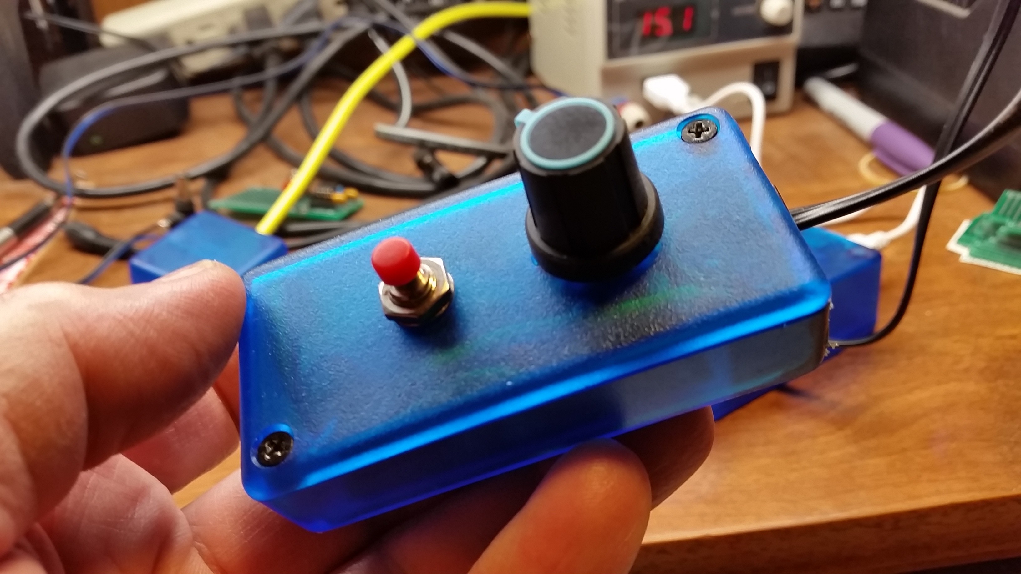
Construction was uneventful, though I really need to find a way to cut cleaner square holes in these boxes for the RJ-11 connectors. With everything buttoned up, and using the power supply from the last build log, both the CV output and the Trigger output worked perfectly.
![]()
Next up... I have the audio amplifier on the breadboard and working, so it's time build that into it's case!
PARTS USED:
- Enclosure https://www.digikey.com/product-detail/en/hammond-manufacturing/1551KTBU/HM1146-ND/2094884
- Dev Board : ( see log #1 for this project )
- 6P4C Verticle RJ11 Jacks https://amzn.to/2HX9LdS
- PIC10F200 Microchip Microcontroller https://www.digikey.com/products/en?keywords=PIC10F200
- MCP601 Microchip Op-Amp https://www.digikey.com/products/en?keywords=MCP601
- 100K Pot https://www.digikey.com/product-detail/en/tt-electronics-bi/P160KNP-0QD20B100K/987-1312-ND/2408889
- Knob, Blue https://www.digikey.com/product-detail/en/davies-molding-llc/1106-A/1722-1315-ND/7593908
- Push Button Switch https://www.digikey.com/product-detail/en/e-switch/PS1024ARED/EG2015-ND/44577
- 0.10 uF Cap (generic)
- 10K Resistor (generic)
- 220 Ohm Resistor (generic)
- LED Indicator (generic)
-
Log 2 - A Prototype Power Supply
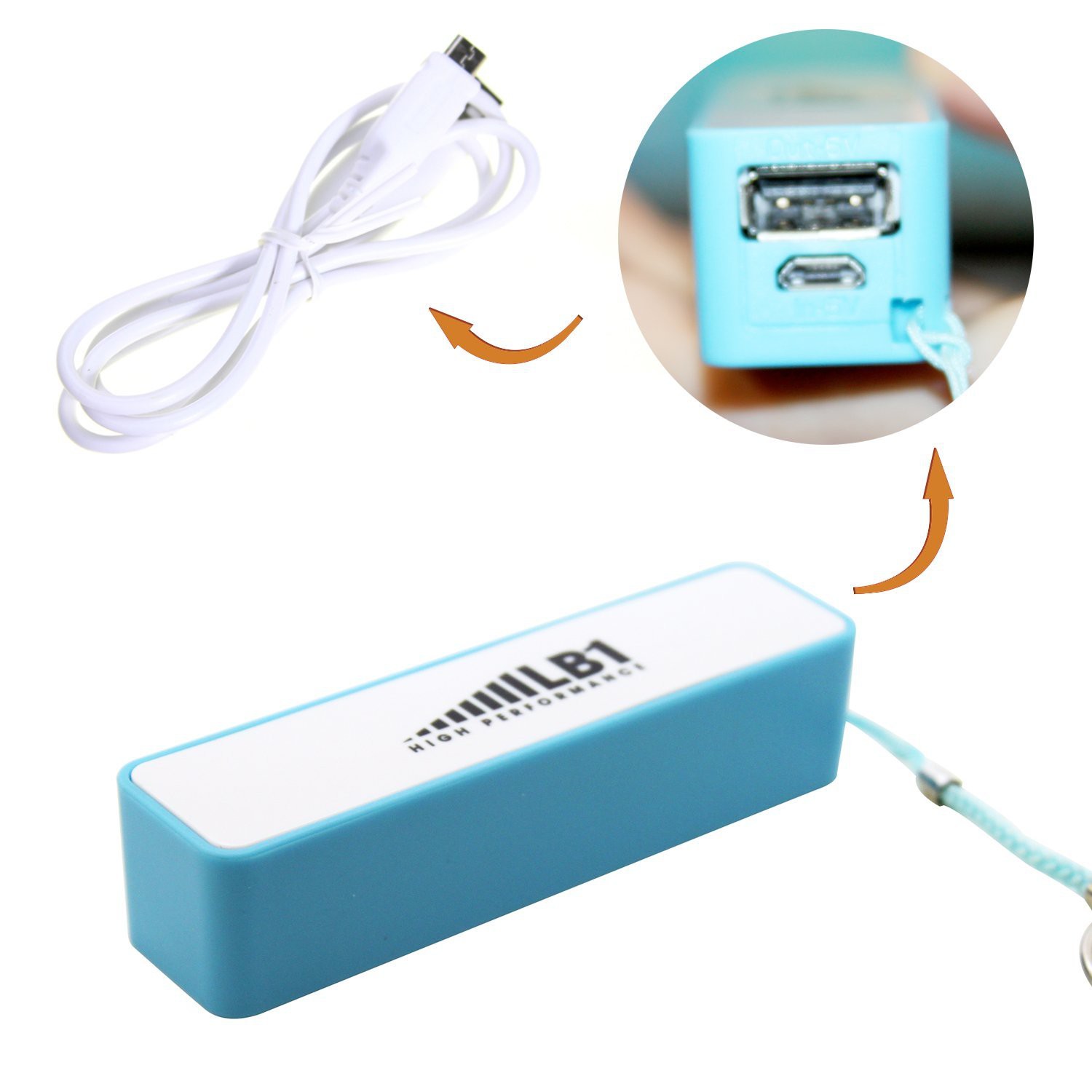
04/23/2018 at 07:09 • 0 commentsSince one of my design goals for this synth is that it be portable, it obviously needs a to operate from a battery pack. There are a lot of good designs for lipo battery packs and charging systems out there. Also quite a few breakout boards and components from the hobbyist suppliers we all know. But since I have no idea what the final current requirements for this system are, I wanted something pretty quick and dirty (and inexpensive) to get things rolling. And I found just the thing.
![]()
Pictured is one of those "Power Bank" battery packs that is designed to recharge your phone when you are not near your charger. Most people probably see just that. I saw, however, a 2200mAh Lipo battery and a charge controller for $6.45 from Amazon. It would have to be reworked though. The output needs to be provided across a pair of RJ-11 connectors which is what all of my modules will be using. I guess you could hack some sort of adapter cable together to make it work, but that certainly would not be sufficiently rugged, and I wanted the battery pack to look like the rest of the modules in the set.
![]()
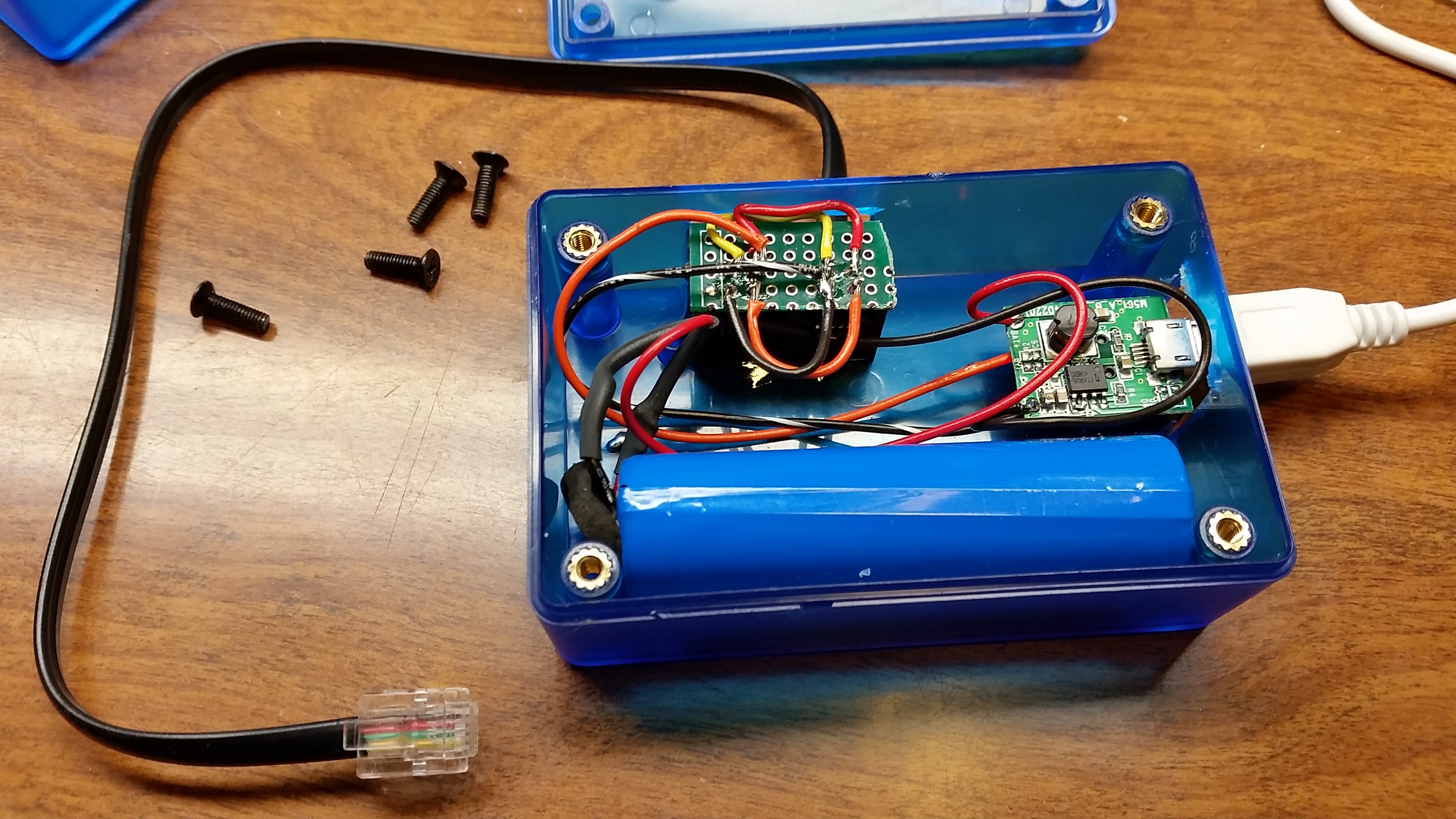
Taking the unit apart was trivial. The cover snapped off easily revealing a single battery cell, and a small circuit board that held the charge controller. The board has a full sized USB socket that provides voltage out, and a mini-USB socket for charging the battery.
I wired the two RJ-11 jacks in parallel, then wired the power leads to the back of the full sized USB connector on the controller board.
![]()
Granted, this is a terribly simple hack. I've included it for two reasons; First, I earlier published that the first module I'd build is the power supply so I thought I should mention it. But second, and more importantly, just wanted to point out that if you're building some form of portable project that needs 5 volts, there's no need to reinvent the wheel. These cell phone battery packs come in all sorts of capacities, and are really a bargain considering what you get!PARTS USED:
PARTS USED:- Enclosure https://www.digikey.com/product-detail/en/hammond-manufacturing/1551KTBU/HM1146-ND/2094884
- LB1 2200mAh 5V Power Bank https://amzn.to/2qYee80
- 6P4C Verticle RJ11 Jacks https://amzn.to/2HX9LdS
-
Log 1 - The 6-8 Pin PIC Proto Board & Enclosure
03/20/2018 at 03:49 • 0 commentsThe modular nature of my HackaDay Prize entry suggests that I will be building a lot of small PIC based circuits. For quite a while I was a huge fan of the tiny PIC Proto board produced by TAUTIC Electronics. Unfortunately they are not available any more so I decided to design my own, and while I was at it, design it to fit into the enclosure I hope to be able to use for my synth modules.
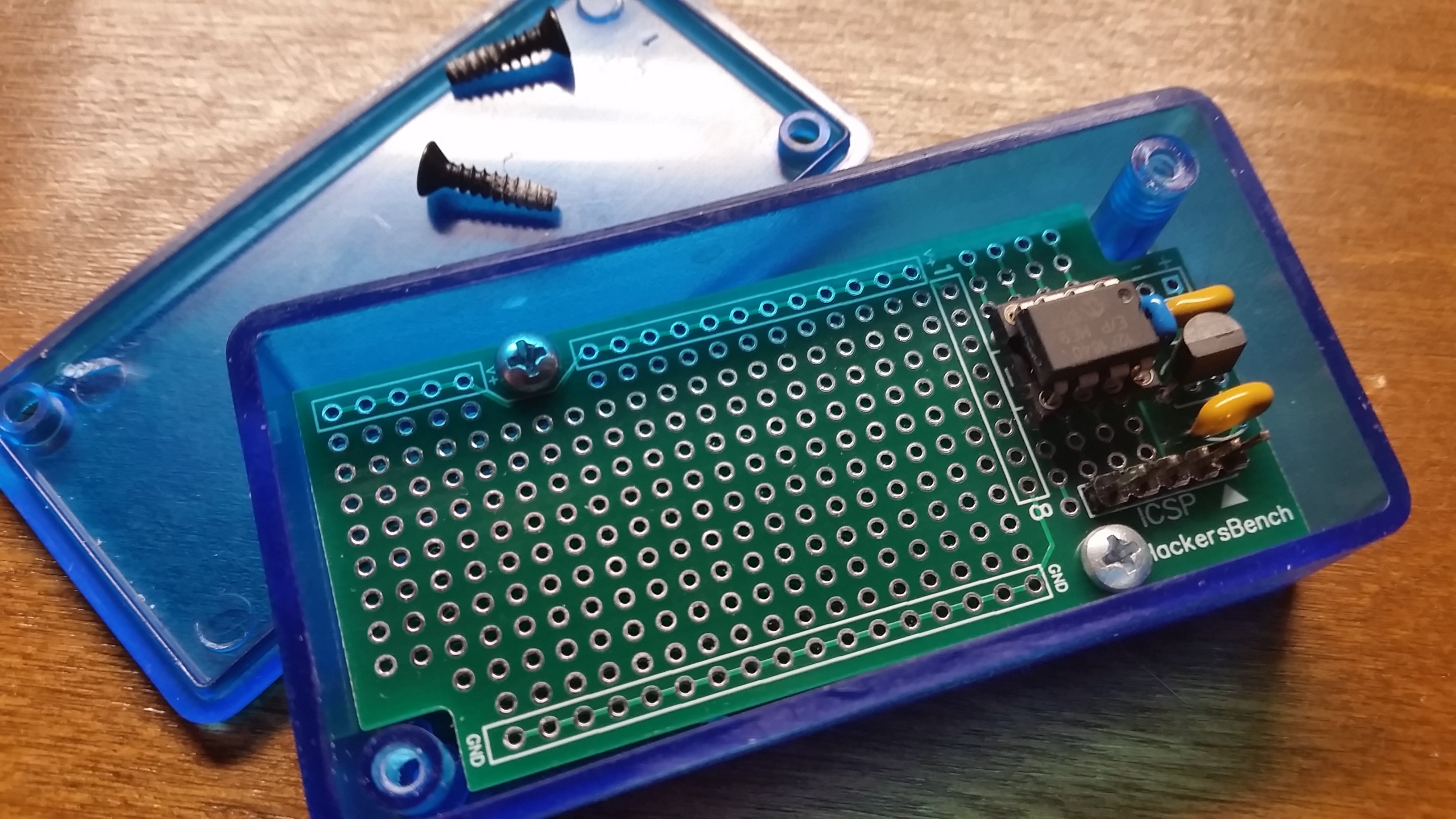
![]() ---------- more ----------
---------- more ----------The board will accept any 6 or 8 pin PIC microcontroller. It has an ICSP header to connect a PIC KIT 3 or 4 for programming, though you'll need some sort of extension cable if you want to program the board while it is in the enclosure.
To the right of the proto area of the PCB you will see eight pads inside a white rectangle. These eight pads are connected to the eight pins of the PIC socket. You can jumper from here to connect the PIC pins to other parts of your circuit. NOTE: If you use a 6-pin device, pads 1 through 3 will be correct, but pad 6 will be pin 4, pad 7 will be pin 5, and pad 8 will be pin 6.
Power and ground busses are also provided along the top and bottom of the proto area.
The board also provides space for an MPC1700 LDO regulator and it's two associated 1uF caps. The MCP1700 is available in several voltages. I'm using 5 volts in this project (MCP-1700-500). You should obviously match the regulator to the voltage requirements of the PIC you are using on this board. If you chose not to use a regulator, you can jumper across it's location so that you can still use the power terminals provided on the PCB.
![]()
I have released this PCB design in the PUBLIC DOMAIN ... no rights are reserved.
You will find the design files and other documentation in the following GIT Repository:
SynBlox : Low Cost Modular Music Synthesizer
Modular Synths are expensive and complicated. I propose a low-cost, entry-level/educational system to make the basics available to anyone.