Jacob Creedon
-
Fails
12/22/2015 at 20:10 • 0 commentsThere were a few hiccups along the way that I thought I would share for the benefit of future hackers.
Initial Design Problems
One of the first challenges was having eyes bigger than my PCB. This project is an entrant in the Square Inch Project so I was limited to a 1"x1" PCB. I really only need playback, but after looking at various interface ICs, I thought it would be neat to have a 2 input 2 output interface with a switch to change the plugs between playback and recording. When It came time to do the board layout I could make it all fit. So I scaled everything back down to my original idea and was able to get everything to fit.
USB Connector Mounting Holes
The USB connector datasheet specifies, and I had created a footprint including plated slotted holes for the shield studs, however, OSH Park does not support plated slots. Now I already knew this, but through some absent-mindedness I did not remember when I was designing it and further more did not notice that the slots were converted to holes in the preview when I submitted the gerbers.
![]()
I ended up working around this by bending up the studs and turning it into surface mount connector and soldering those studs on top of the pad. The lesson learned here is to double check the preview you get back from OSH Park, it is pretty accurate.
Further USB Connector Woes
Unfortunately without the holes, there is no way to keep the connector aligned. With the pin pitch of the connector and with the connector pins basically being under the pad, this made the reflow of the connector a little more error prone and made rework a lot more tricky.
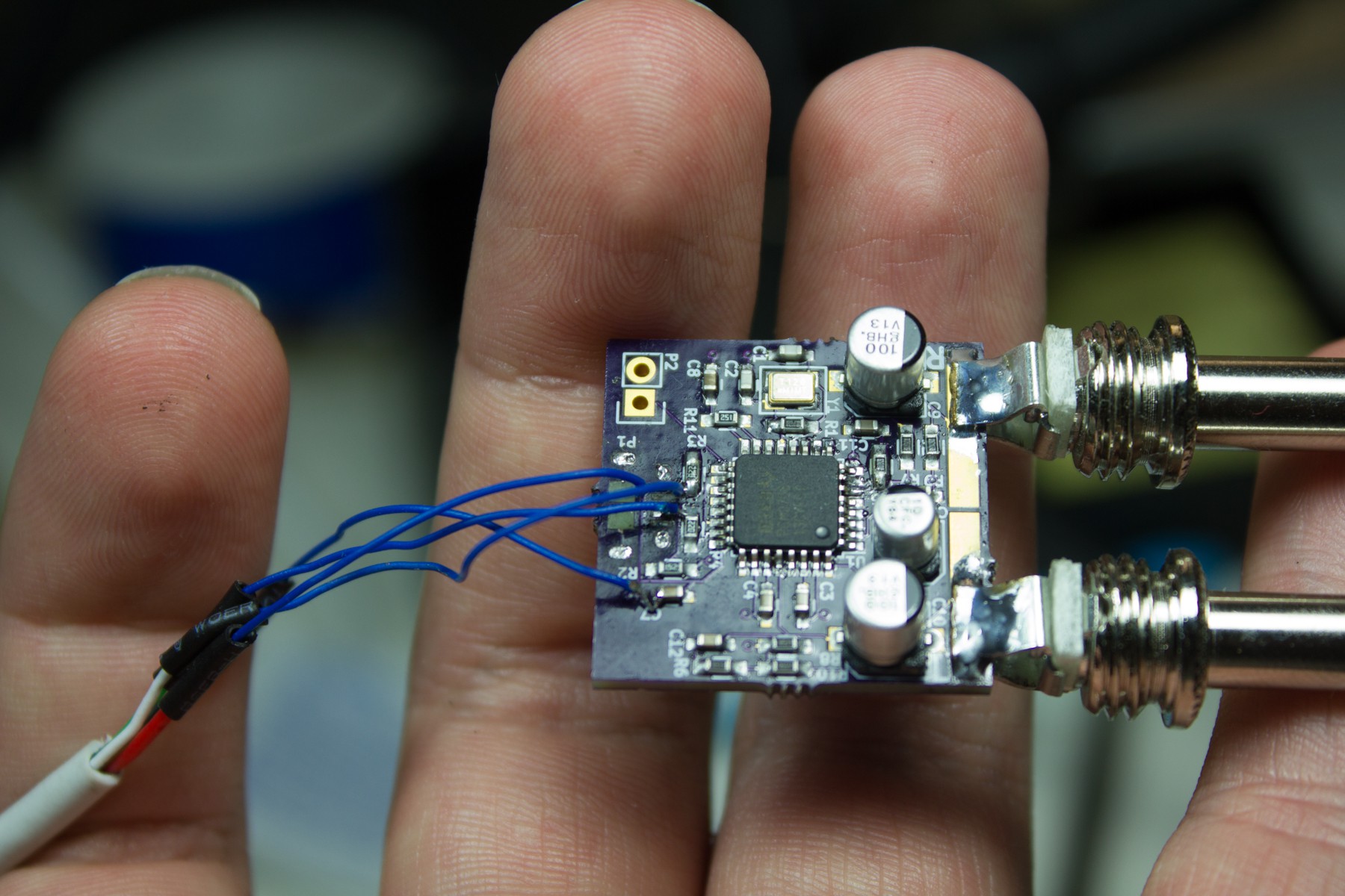
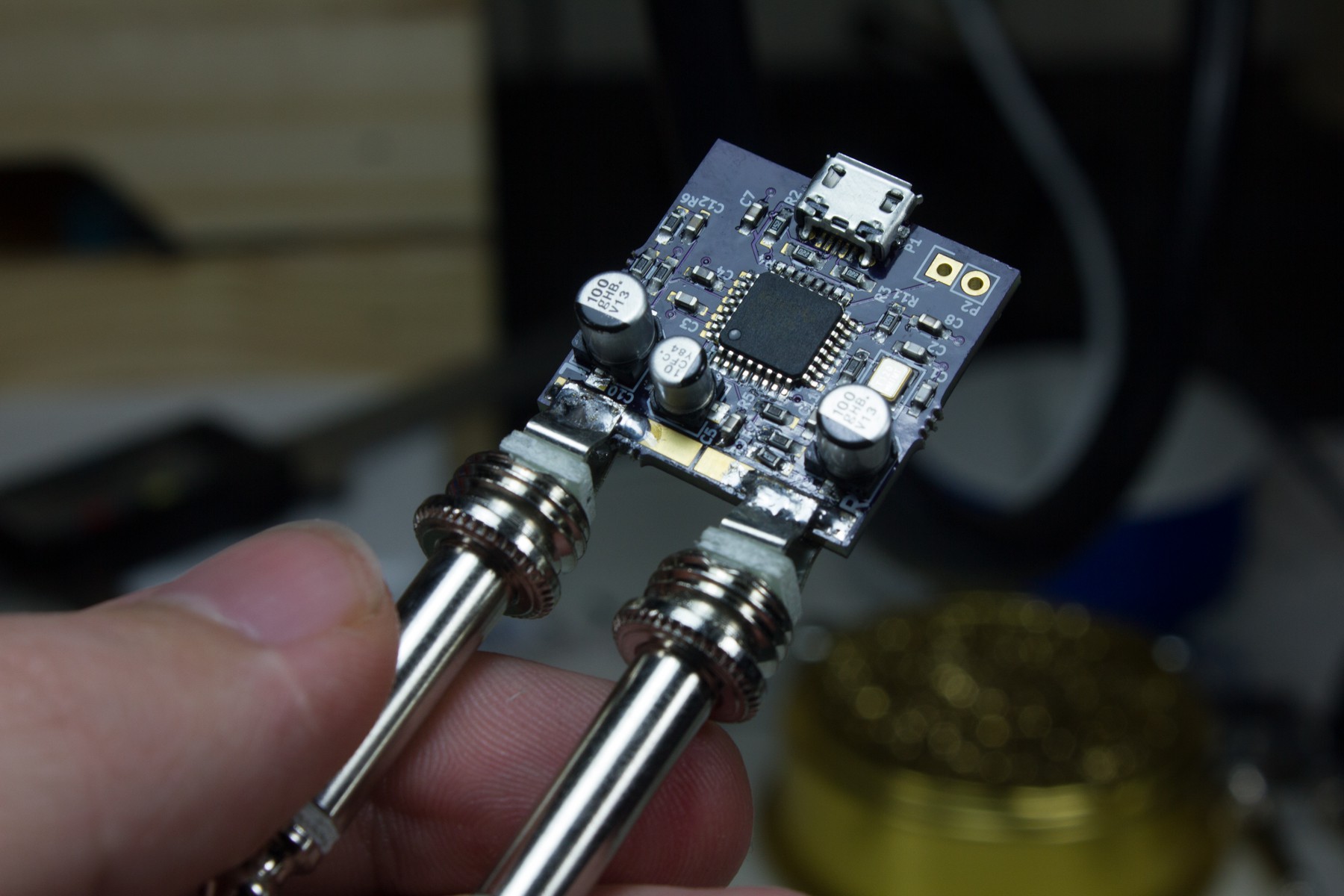
On my first board there ended up being a short between a couple of pins. After various attempts to reflow, rework, desolder, and resolder this connector, I had mangled up the board pretty bad and torn up a few pads. Eventually I resorted to just soldering a USB A pigtail to various pads directly on the board to give me this monstrosity:
![]()
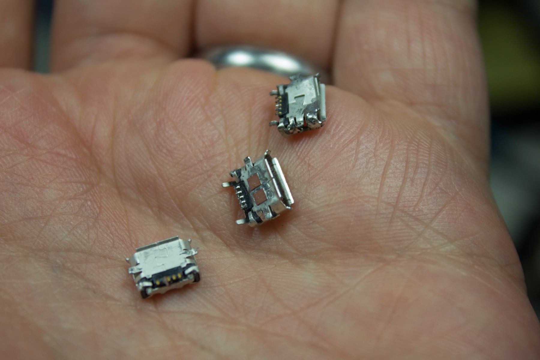
Leaving behind a trail of mangled USB Micro B connectors.
![]()
Thankfully with lessons learned in dealing with Micro B connectors, the next two boards were assembled just fine.
-
Conclusion
12/22/2015 at 19:19 • 0 comments![]()
Design Retrospective
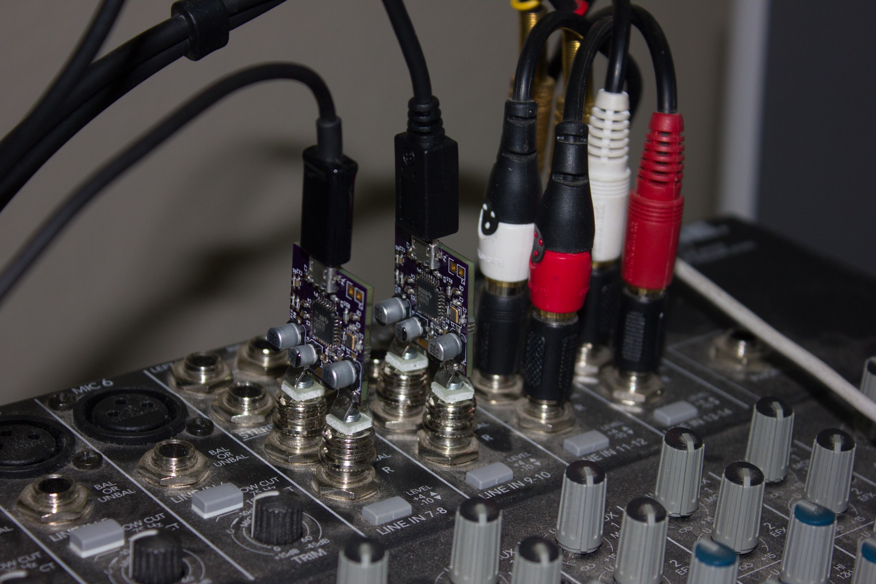
Overall I am pretty satisfied with how this project turned out. The audio quality is superb (at least compared to my previous set up) and the device fits nicely within the channel strip, as opposed to having clunky interface boxes. There are a few things I would want to improve for the next iteration.
First would be to come up with a better overall mechanical design. Depending on the holding force of jacks on the mixer, it can be a little tricky to unplug it from a mixer. I would probably want to figure out some kind of external (3D printed?) case to screw the plugs to. I would also probably add mounting holes to the PCB to offer some additional stability/strain relief.
Second, would be to see if I could squeeze in an external ROM. The PCM2706 does not require an external ROM, however, if you want to use custom USB descriptor strings, you would have to set those up on the ROM. This would be useful for when you have multiple devices connected to the same computer and you wanted each to have a unique name. As it stands right now, I don't have a need for multiple cards on a single computer, so I had left it out of this first iteration.
One question I had from someone in the Hacker Channel has the reasoning behind the selection of the PCM2706 as the DAC for this project. The selection was based upon the goals of this project, keep it small and keep it cheap. The PCM2706, as far as I have been able to tell, if the cheapest single chip solution I could find. The typical USB DAC design pattern these days is a two chip solution, one to go from USB to I2S and another to go from I2S to audio. This ends up being a problem for two reasons: first, two chips is more board area which makes it larger and second, two chips would be more expensive than one. The PCM2706 is an older design (2003 I think), and it is limited to 16-bit/48kHz sample depth/rate, however, for playback that is a non-issue. If I were to do it again, I think I would still use the PCM2706, for reasons of cost and simplicity. If I were to make another design for recording, I would probably go the two chip route for a higher sample rate as there are some advantages for higher sample rates for recording.
Video Demonstration
-
Testing
12/22/2015 at 18:28 • 0 commentsAfter the PCB has been assembled and reflowed. It is time to test to make sure there are no shorts or opens. For testing this I opted to do continuity checks on the USB side, and a system check on the audio side.
USB
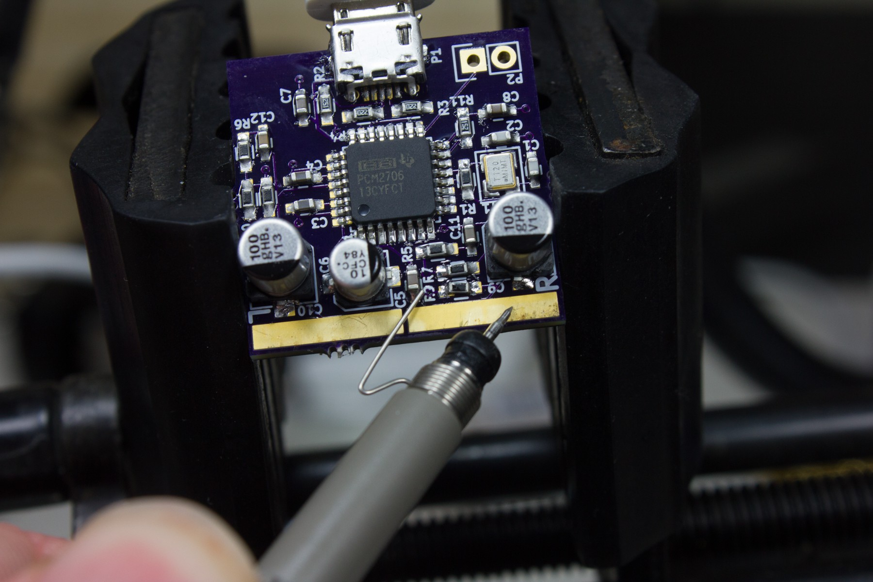
The USB connector was the most tricky to solder because the pins were underneath it, and the most prone to failure. The first step is to make sure there are no shorts between any of the pins. Next make sure that the pins actually reach their corresponding pin on the IC. Finally, make sure that the pins on the connector are not open between it and the cable.
![]()
Audio
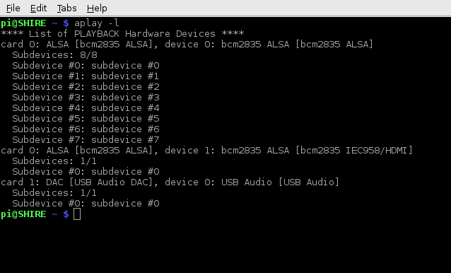
Once the USB side is tested, we connect it to a computer to test audio output. For this testing I used a Raspberry Pi, so even if I messed something up, ruining a port on a Pi is not as bad as on my main computer. The first check is to see if ALSA picks it up. This can be done by running:
aplay -l
to list connected playback devices.
![]()
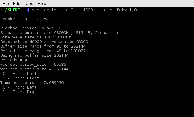
So here we can see the sound card "USB Audi DAC" show up as card 1 subdevice 0. In ALSA this equates to the designation `hw:1,0`. Using that information we can then use `speaker-test` to generate test signals. I used the following command:
speaker-test -c 2 -f 1000 - t sine -D hw:1,0to generate a 1kHz sine wave on both channels.
![]()
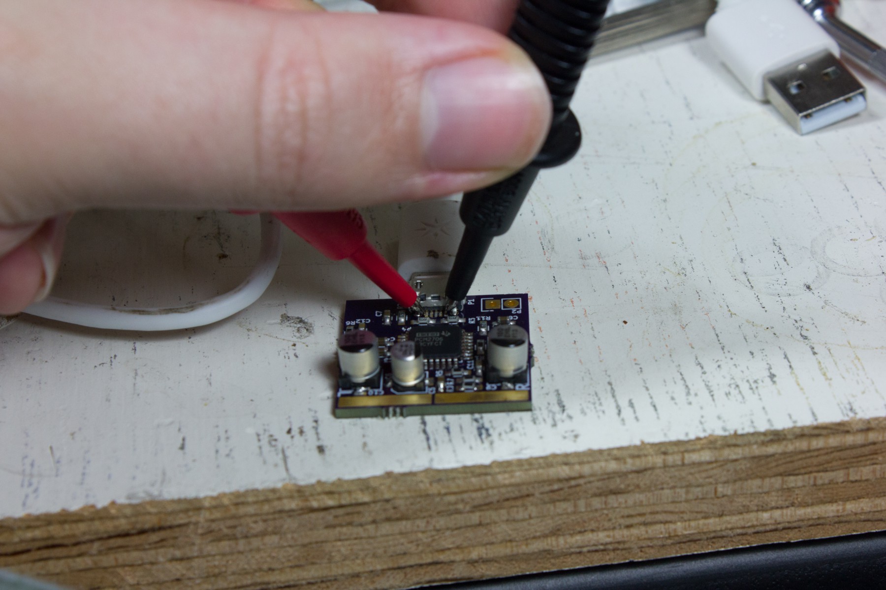
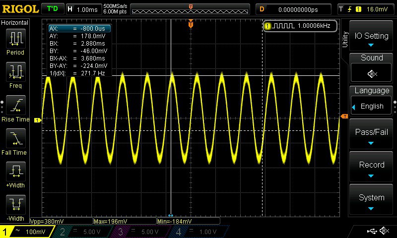
This will alternate that sound on each channel every couple of seconds. We can then probe the pads with an oscilloscope to confirm the output.
![]()
![]()
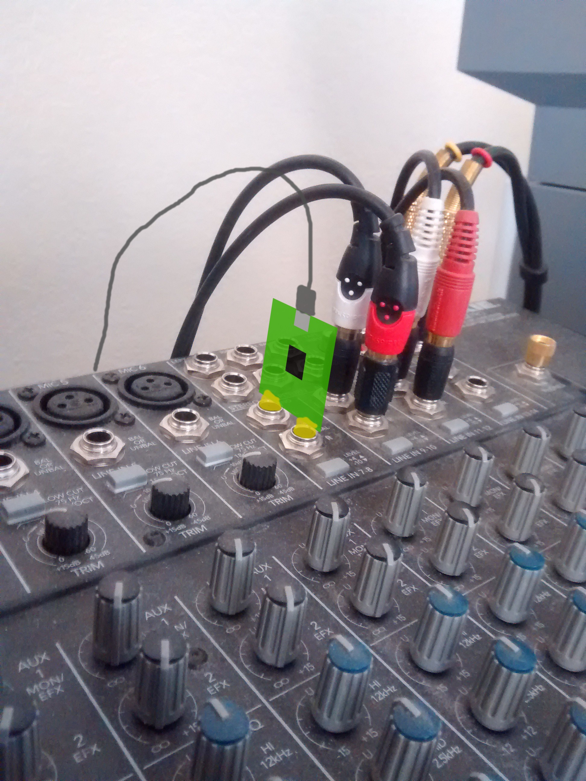
Once both channels are tested and looking good. We are ready to solder on the plugs and connect it to a mixer.
-
The Build
12/22/2015 at 18:05 • 0 commentsThe PCB
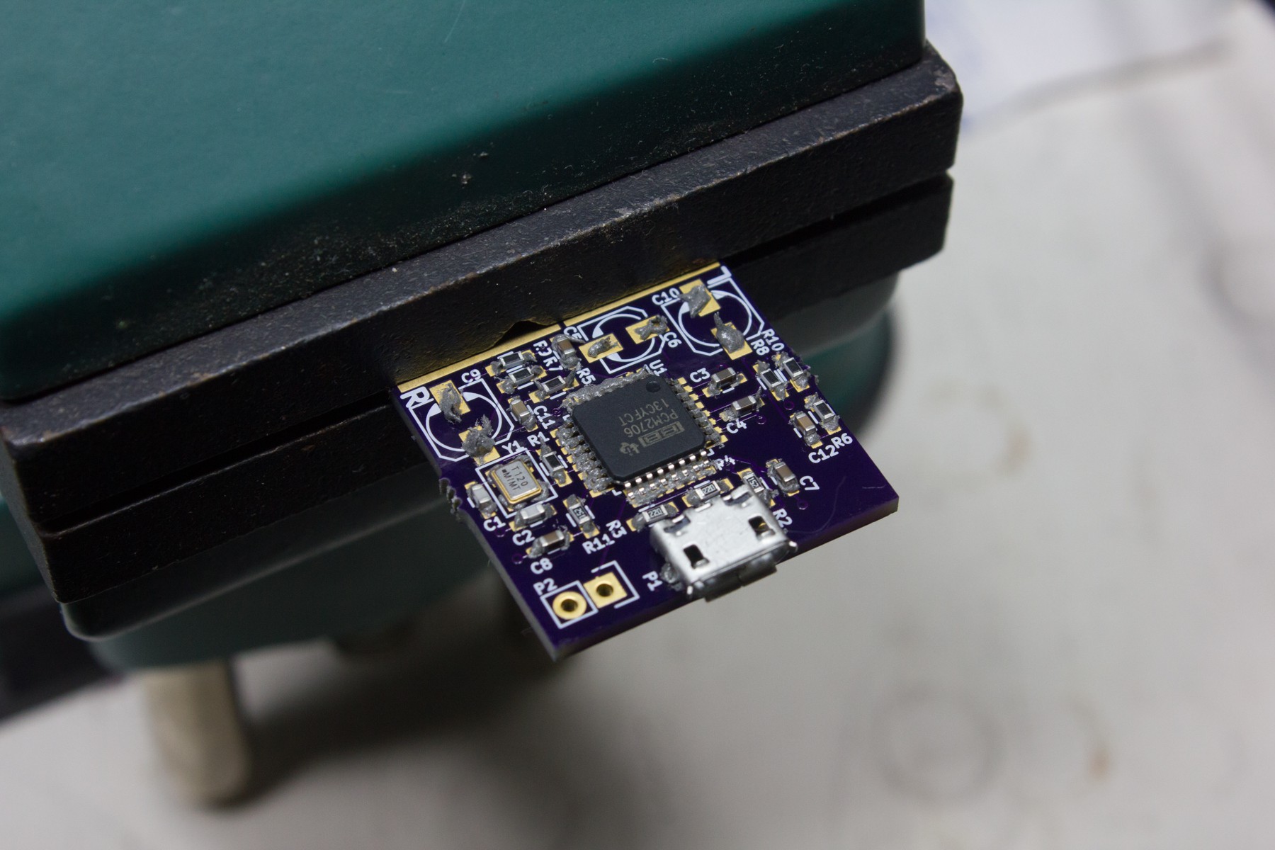
Assembly was done using manually applied soldering paste and reflowing it with a hot air rework station.
![]()
![]()
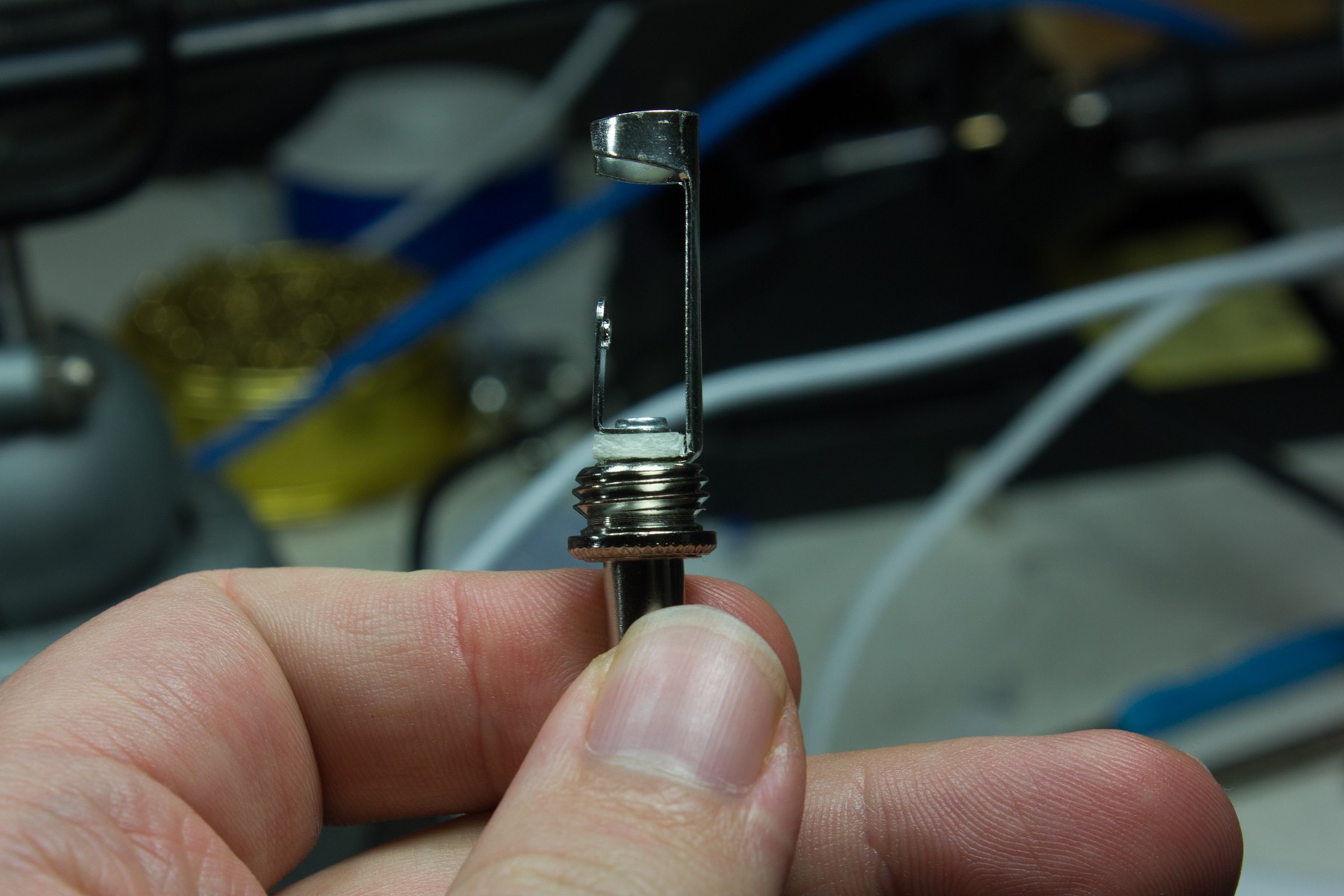
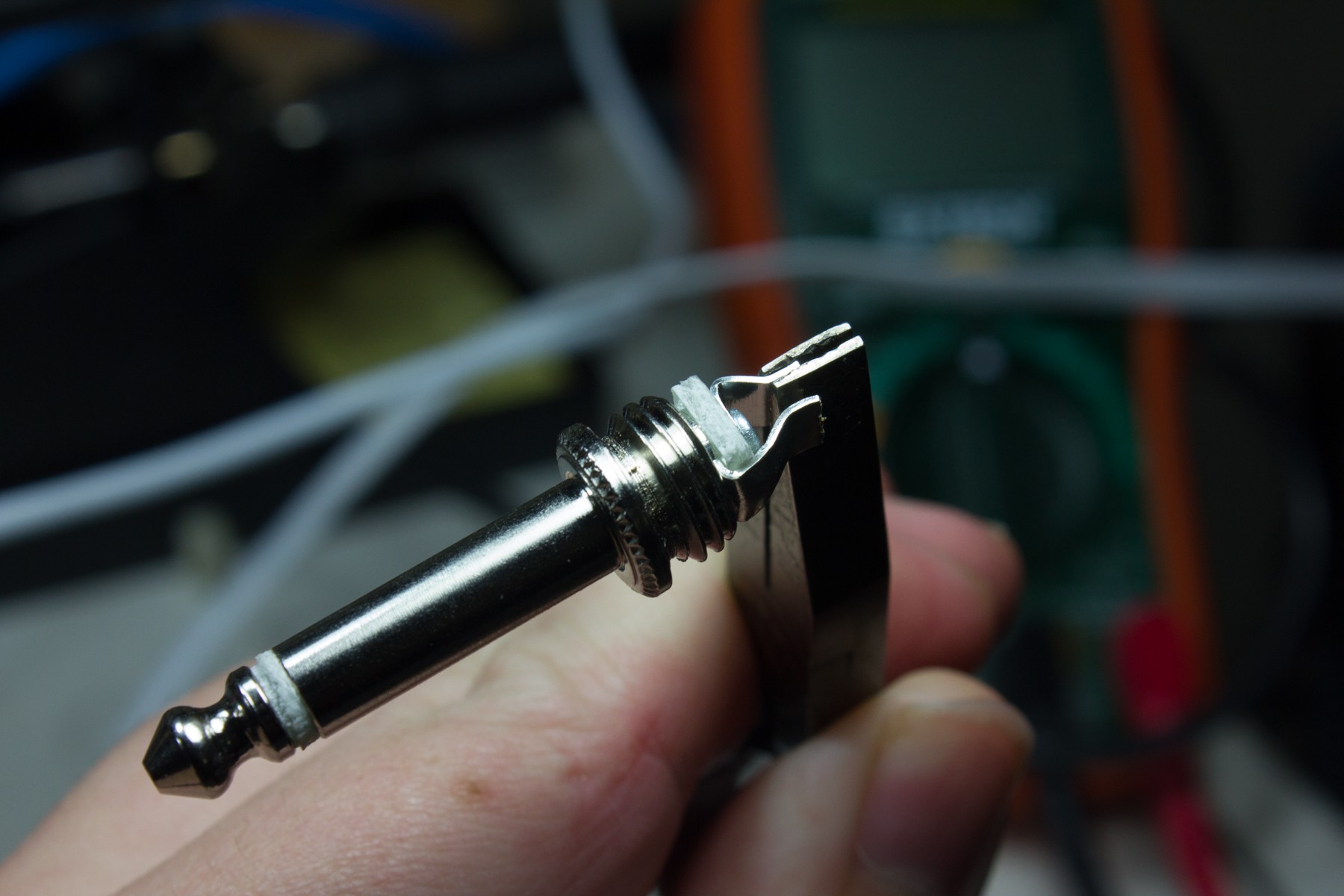
The Plugs
The 1/4" phono plugs are just standard solder lug plugs where I have cut the lugs down and bent them in towards each other.
![]()
![]()
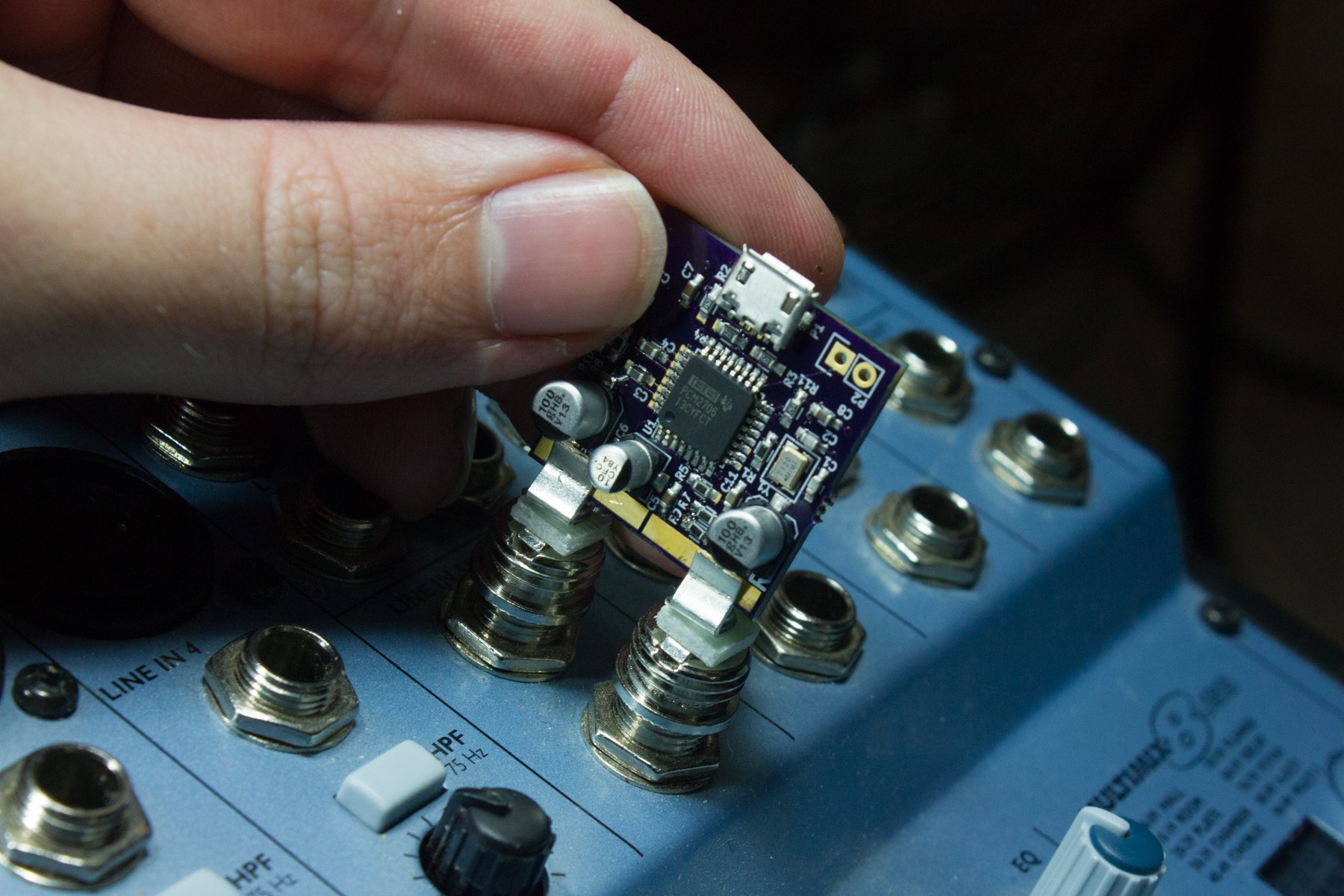
Marking the placement of the plugs.
![]()
The pads for the plugs were extended along the whole length of the PCB edge so that different plug spacings could be used if they were different between mixers. However, it turns out, (at least with the two mixers I have with me, which are different brands) that spacing might be standard. I'll have to check a few other mixers when I get a chance, but it would be pretty convenient if that were the case.
![]()
-
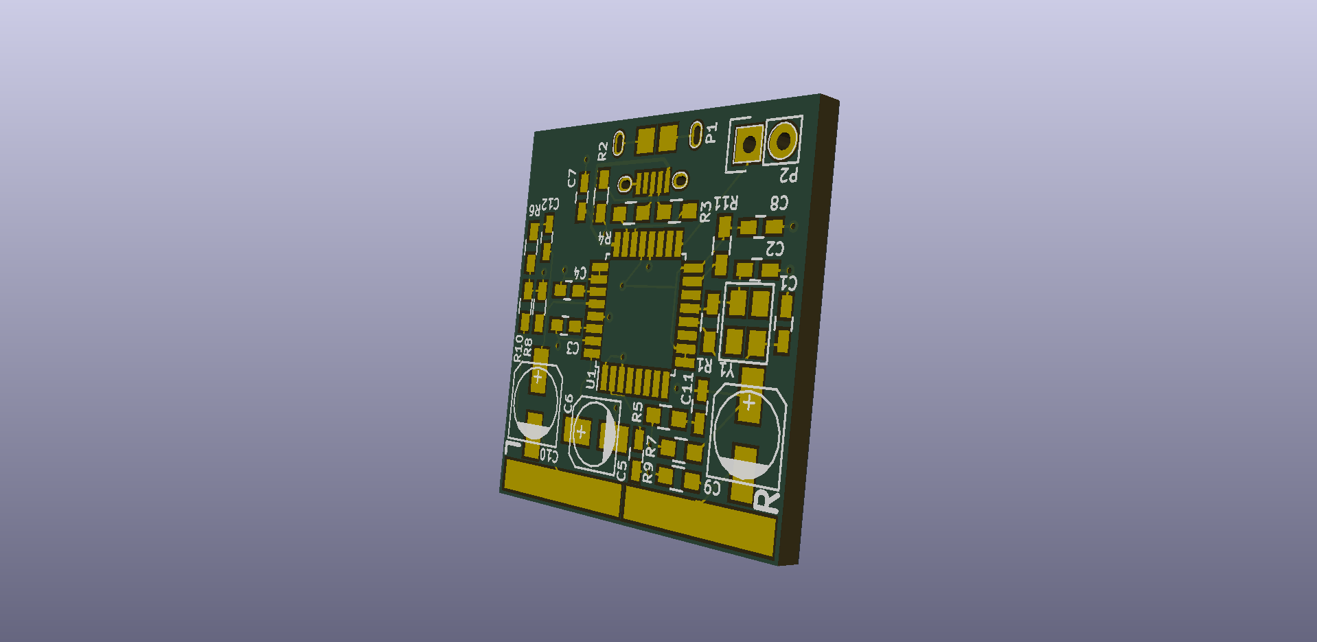
The Design
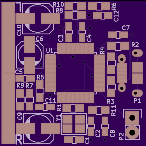
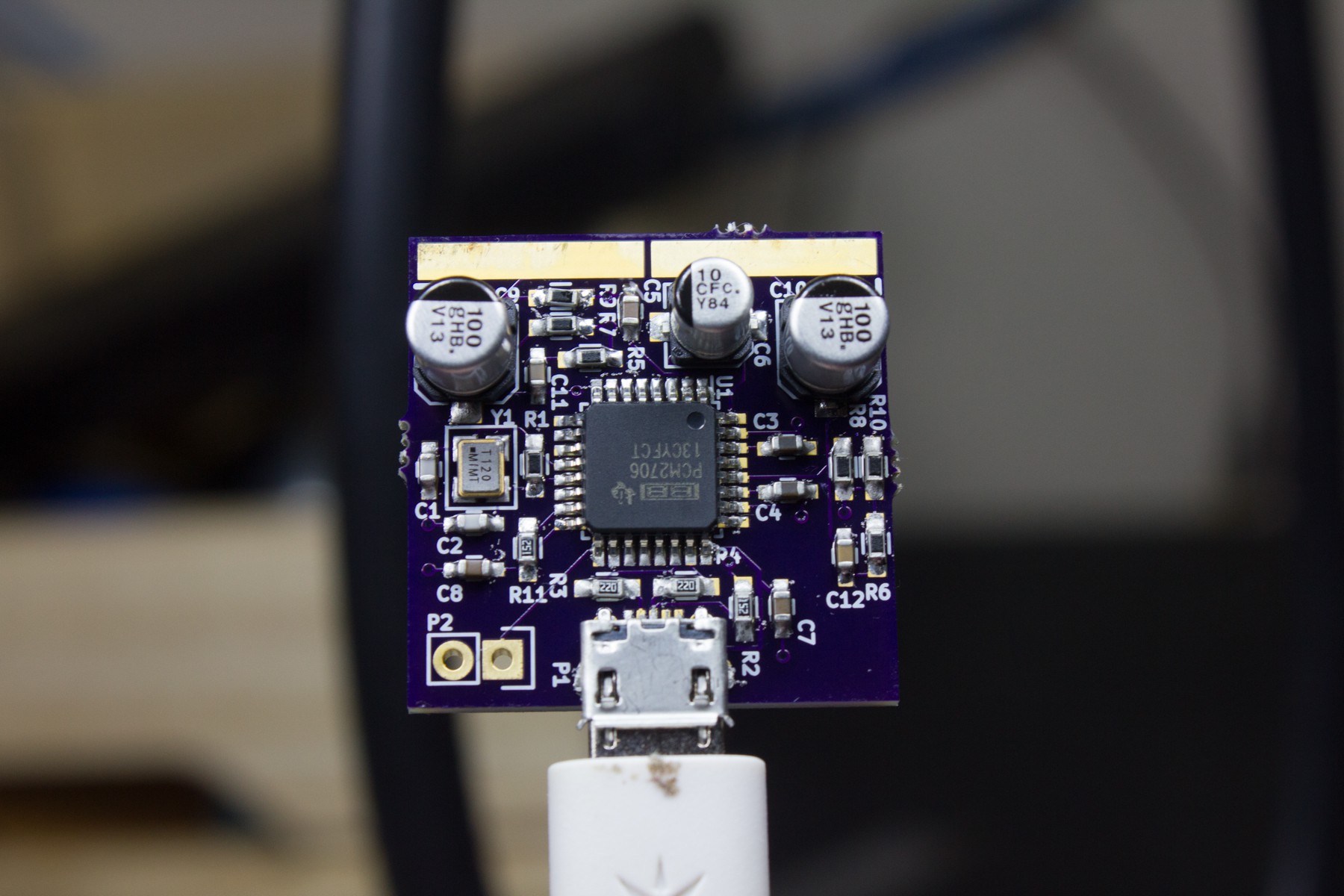
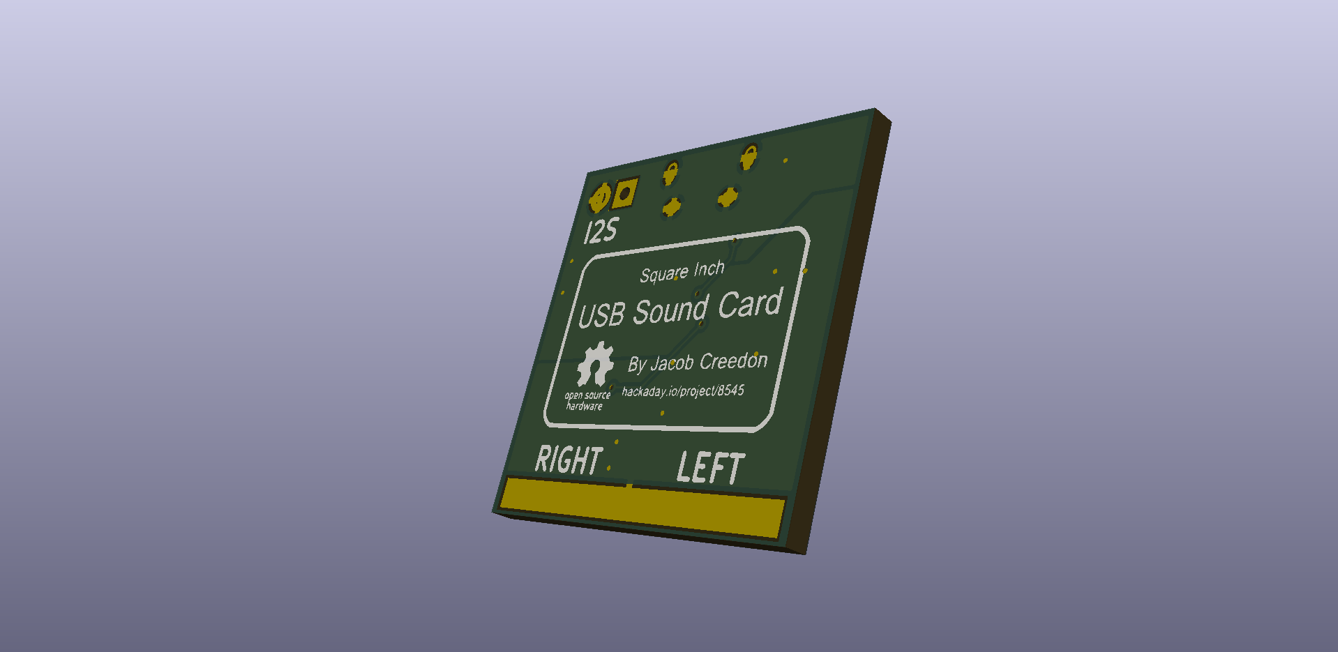
12/01/2015 at 04:07 • 0 commentsAfter playing around with a few ideas, I settled on building a design around the TI PCM2706. The schematic is based heavily on the reference design from the datasheet. The EDA files (KiCad), schematic pdf, and gerbers can all be found on the github repository. I've included below renderings of the PCB in 3D.
Front
![]()
Back
![]()
-
The Concept
11/23/2015 at 23:38 • 0 commentsThis is a project to submit to the Square Inch Project contest but to also fill a personal need. The idea is to be able to quickly add a digital channel to an analog mixer by having a compact, bus powered, USB Class Compliant audio interface.
![]()
Square Inch USB Sound Card
Small audio interface for adding a digital channel to an analog mixer.