jaromir.sukuba
-
How to
12/23/2015 at 15:27 • 5 commentsIn case you'd like to build it, you have two possibilities when it comes to hardware - use off the shelf arduino board or build dedicated hardware.
Hardware option 1 - Arduino hardware
Take any Arduino with ATmega328P, like Uno or most of cheap chinese knock-off boards. Considering the target has its own power supply, connect GND, MCLR, PGC and PGD lines to respective pins on arduino as follows:
Arduino pin = AVR pin Target PIC pin Comment GND GND GND ground 5V VDD VDD * optional - power supply for PIC MCU
you may power target from other sourceA3 PC3 MCLR reset line of PIC MCU A1 PC1 PGD programming data line A0 PC0 PGC programming clock line * If you are powering target PIC from other power source (in circuit programming), series resistors (something like 470-1000 Ohms) in MCLR, PGC and PGD lines are good idea, it will somehow decrease currents flowing through IO pins due to power supplies differences between arduino and target board. In this configuration, even targets running at 3,3V are possible to program, though it is dirty practice.
Power it up, no smoke should be released. Run arduino IDE, open programmer firmware from github, complie and upload to arduino board - now you have PIC programmer ready to go. Go to software below.
Hardware option 2 - dedicated board
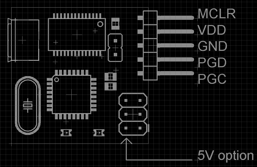
Considering the target has its own power supply, connect GND, MCLR, PGC and PGD lines to respective pins on PIC programmer (notice the pinout similar to PICkit programmers). Vdd line is not currently used ad it is not needed for operation of programmer, but future revisions of firmware may take advantage of this pin and detect target VDD.
![]()
If you wish to power the target from programmer, you can use 5V from AVR ISP connector.
Use another arduino or ISP programmer to load Arduino UNO bootloader to PIC programmer board (performed onle once), turning it into regular arduino.
Ensure JP2 is closed, then you can load new firmware into PIC programmer using regular Arduino IDE. Open jumper JP2. Now you have your programmer ready to go, move on to software.
Software
When running under Linux, download source from github and run
gcc -Wall pp2.c -o pp2This should buiild executable pp2.
Under windows, you can download binary from github. Alternatively, you can build it from source - install minGW and run
gcc -Wall pp2.c -o pp2
- the same procedure as on Linux. This should result in silent build with pp2.exe executable created.
Running the executable with no parameters should only bring banner pp programmer.
If you have .hex file ready to program into PIC, convert it to binary file using utility hex2bin, available here for windows - using command
hex2bin -e bin file.hex
resulting in file.bin creation.Now, having functional pp2 software and binary to be downloaded, run command
./pp2 -c /dev/ttyACM0 -t 16f1829 file.bin
under Linux, where -c parameter denotes port to be accessed, -t parameter defines PIC to be programmed and last parameter is binary file to be downloaded; or
pp2.exe -c COM30 -t 16f1829 file.bin
under Windows to run the actual software. And program the target PIC.
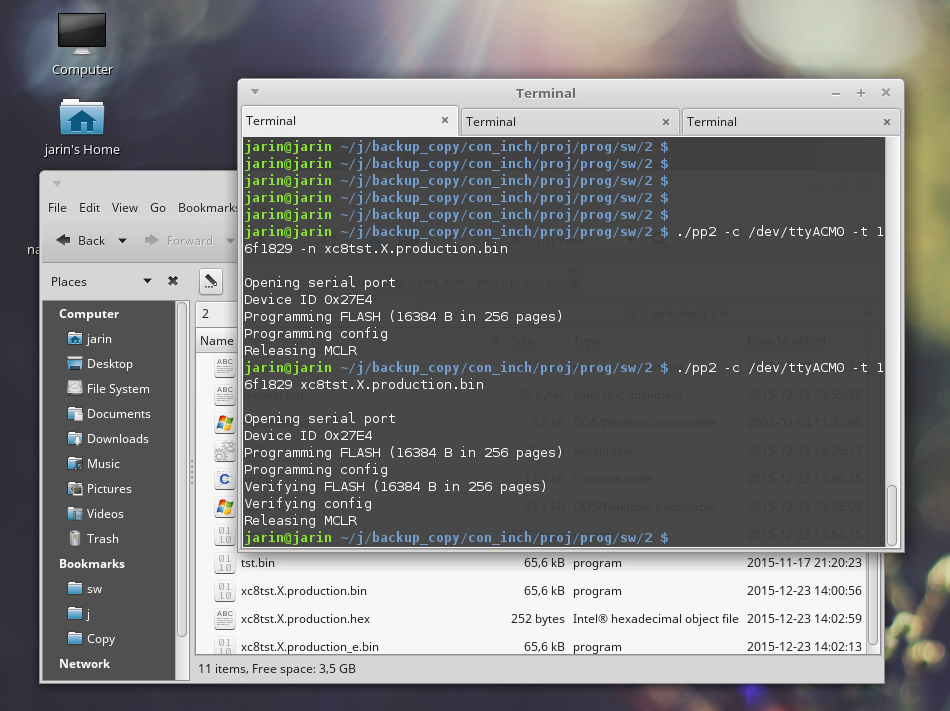
The result should look like this:
$ ./pp2 -c /dev/ttyACM0 -t 16f1829 file.bin

Opening serial port
Device ID 0x27E4
Programming FLASH (16384 B in 256 pages)
Programming config
Verifying FLASH (16384 B in 256 pages)
Verifying config
Releasing MCLR
And now your PIC should be programmed and running.
Notes on software
If you are running the hardware on generic arduino board or you forget to open jumper JP2 after loading firmware on dedicated hardware, you may need to insert waiting time after opening serial port and before communication - to ensure Arduino bootloader times out and takes control to programmer firmware. It should look like this
pp2.exe -c COM30 -s 1700 -t 16f1829 file.bin
where number after -s switch defines the number of miliseconds to wait after opening the serial port.
You may omit the actual programming using -p switch or verification using -n switch, when using both the programmer only checks target device signature and exits.
$ ./pp2 -c /dev/ttyACM0 -p -n -t 16f1829 file.bin

Opening serial port
Device ID 0x27E4
Releasing MCLR
you can add some debug output info using -v parameter, ranging from -v 1 to -v 4
-
Updates, programmer in action
12/23/2015 at 14:27 • 0 commentsToday I made some updates to this project:
- the programmer functionality is actually tested on my 25x25mm hardware, not just on generic arduino board
- BOM is available not just as parts list here on project site, but also on github
- PIC16F1829, PIC16F1825, PIC16LF1829 and PIC16LF1825 are added to supported devices list on current software
Then I set up simple project in MPLABX with main.c
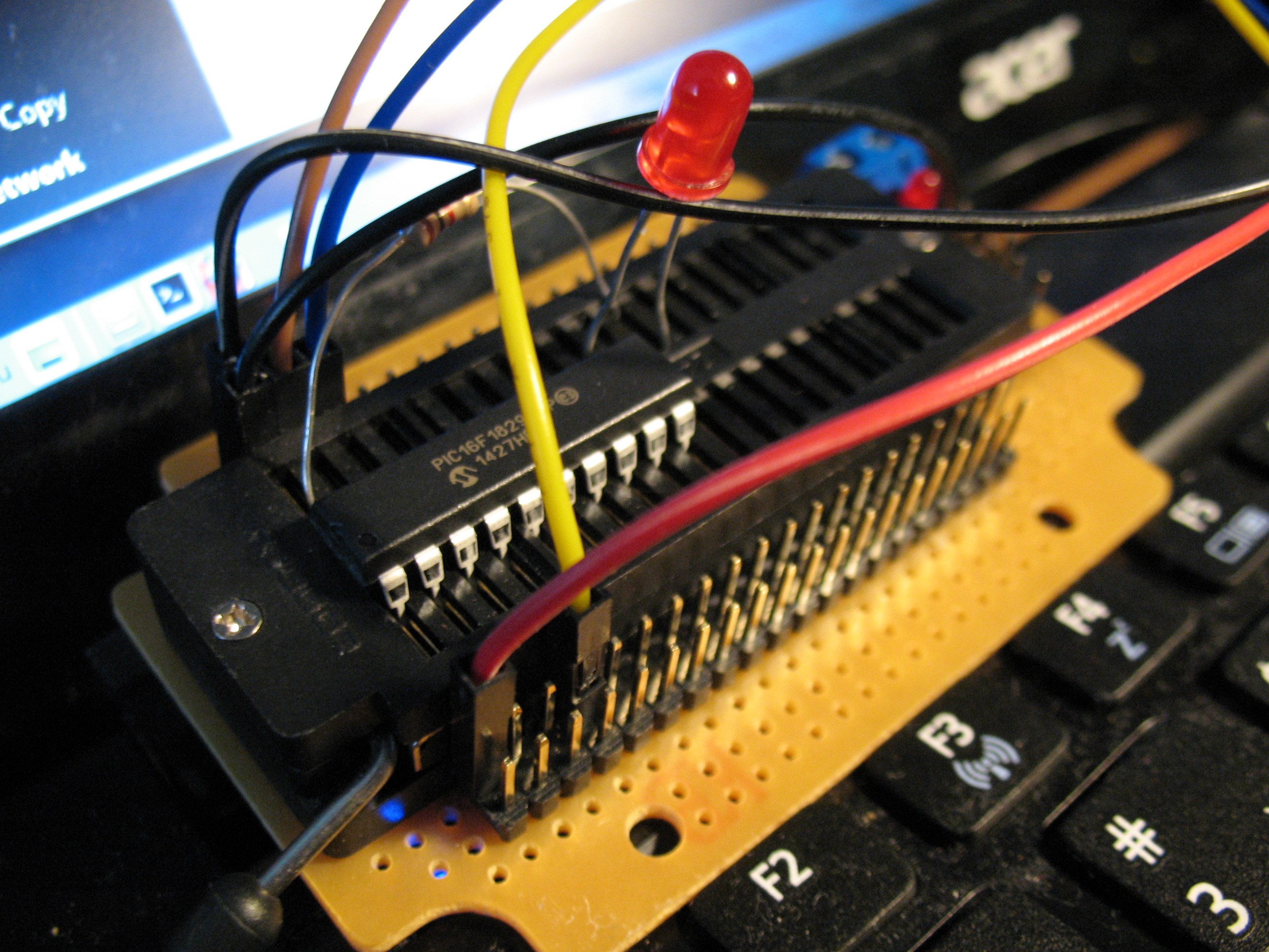
#include <xc.h>
#define    _XTAL_FREQ    (2000000*1)

#pragma config FOSC = INTOSC
#pragma config WDTE = OFF
#pragma config PWRTE = ON
#pragma config MCLRE = ON
#pragma config BOREN = OFF
#pragma config PLLEN = OFF
#pragma config BORV = LO
#pragma config LVP = ON

void main(void)
    {
    OSCCON = 0x60;
    TRISBbits.TRISB6 = 0;
    while (1)
        {
        LATBbits.LATB6 = 1;
        __delay_ms(100);
        LATBbits.LATB6 = 0;
        __delay_ms(100);
        }
    }
doing nothing but setting up config bits and blinking a LED connected to pin RB6 and set up experiment board accordingly
![]()
Nothing but LED on RB6, in series with resistor, programming cables leading to my programmer.
MPLABX generated hex file and using bin2hex program - windows version is available here - I converted the hex file to binary. And after running
./pp2 -c /dev/ttyACM0 -t 16f1829 xc8tst.X.production.bin
from where pp2 binary and bin file to program resides - believe or not - it worked flawlessly on first try.
![]()
and LED blinked, as captured on this crappy video
Sorry for that video quality, but my favorite camera is out of order now.
Windows users should enter something like
pp2 -c COM30 -t 16f1829 xc8tst.X.production.bin
where COM30 is COM port created by the device. It is tested on win7 64-bit. -
Burn bootloader, burn!
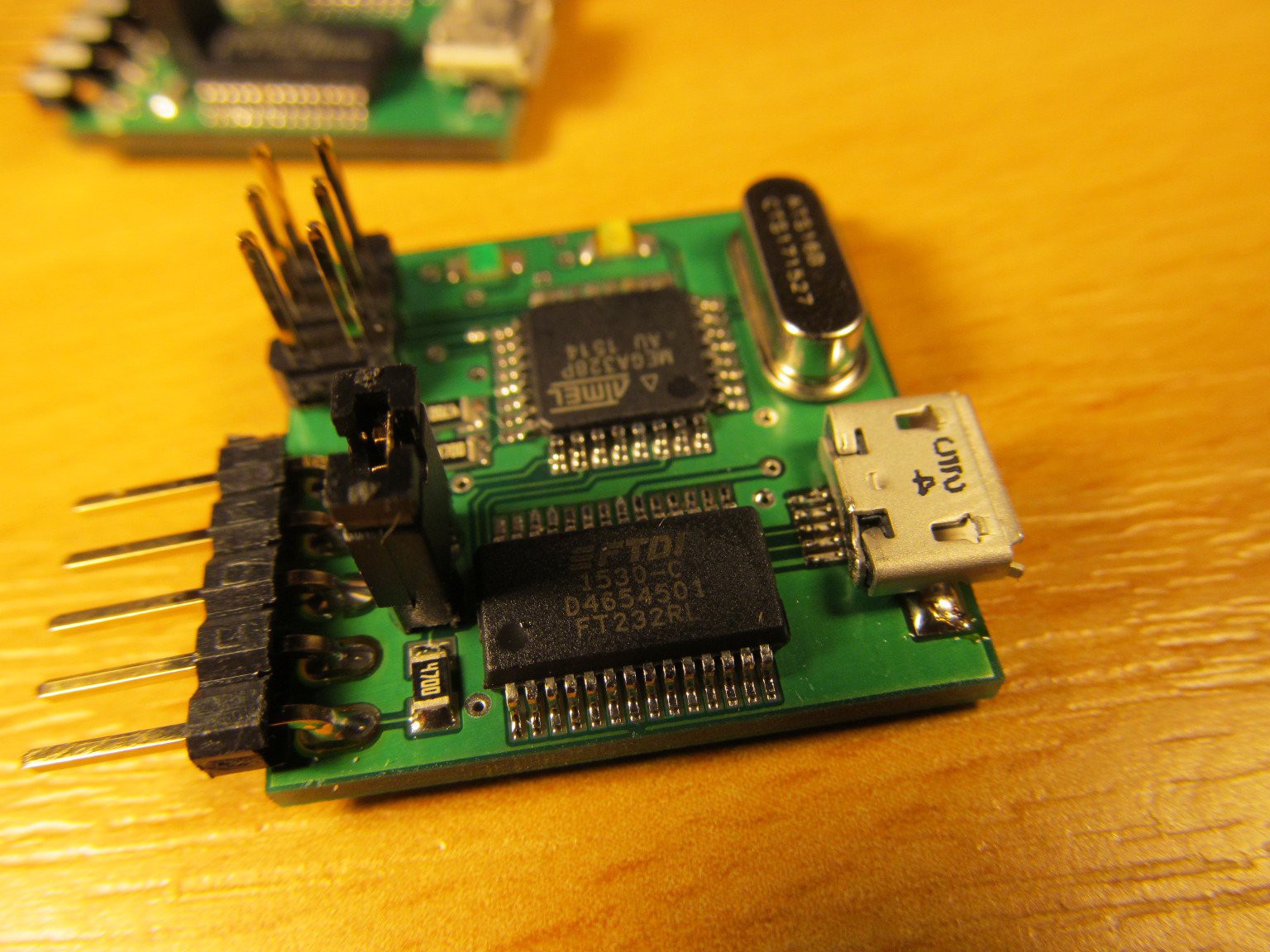
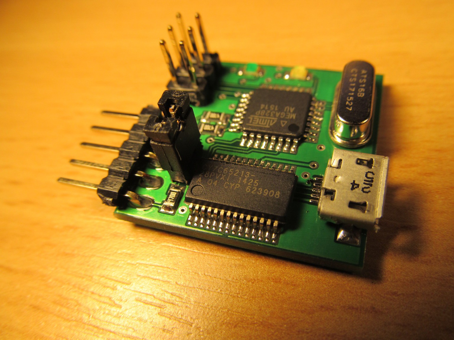
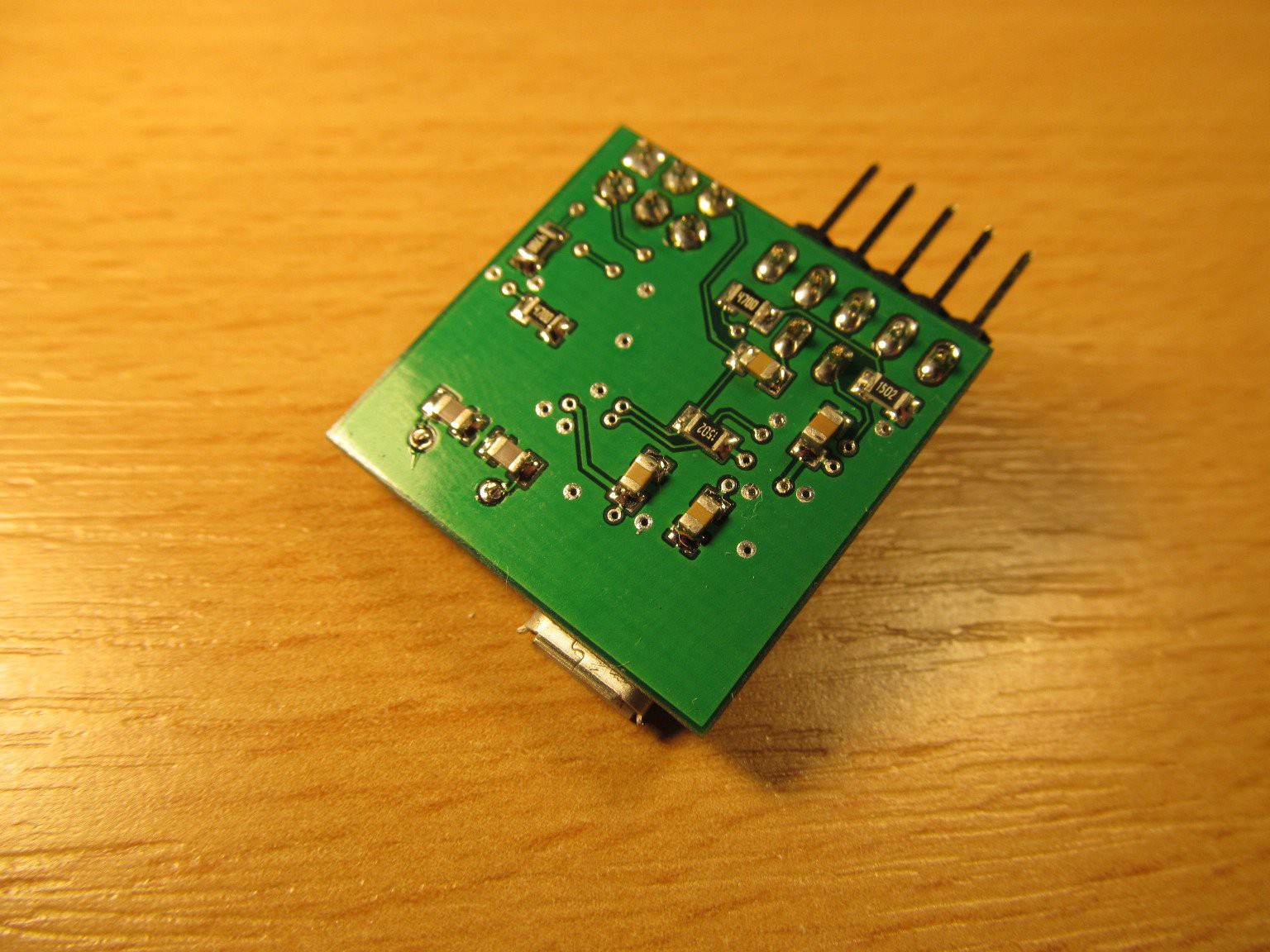
12/10/2015 at 21:43 • 0 commentsYesterday the boards arrived - I couldn't wait any longer, so I populated two of the boards.
![]()
![]()
You probably noticed tiny difference between the boards - first one is populated by ubiquitous FT232RL, while the second one by CY7C65213. This device is interesting as FT232RL pin-to-pin replacement in most of simple designs so while board was designed for FT232RL, so I simply soldered the CY7C65213 on second board with no changes.
In fact, I'm quite happy with FT232RL, but there are people around nervous about FTDI devices, so having another option is good. Nice bonus is that the Cypress part costs approximately half of the FTDI price.
![]()
I connected both of the boards to another arduino board
and burned AVR ISP example to main arduino board, then burned the actual bootloader via Tools->Burn bootloader selection. After a few seconds the green LED on my board blinked a few times, indicating the bootloader hooked up after reset.![]()
After disconnecting the ISP jumpers and inserting micro-USB connector board went alive and in a second new ttyUSBx device appeared for FTDI board or ttyACMx device for CYpress board, respectively. When using windows, both the boards created virtual COM port.
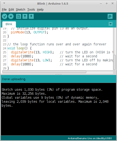
I tried the obvious first-time program, LED blink and everything worked as expected:
And green LED on PB5 (arduino pin 13) blinked:![]()
So I've got two arduino derivative boards, ready to become PIC ISP programmers, plus I explored new CY7C65213 device, everything going smoothly.![]()
-
Why, what and how
11/24/2015 at 10:45 • 0 commentsWHY:
Well, mostly because I like Microchip MCUs, though they aren't that much popular in open-source projects. This is where diversity is a good thing, I decided to build PIC16F programmer based on Arduino basis (just because of cost and availability), serving together with SDCC compiler as fully usable development toolchain. I'm going to demonstrate usability of this combo by #PIC16F1xxx Arduino based programmer project.
WHAT:
It is PIC16F1xxx programmer. It can program PIC16F1xxx devices. Period.
For now it can't do any debugging (though technically possible I don't feel like I can manage gdb fork or something on PC side).
It will never (=unless HW of programmer is changed) work with older PIC16Fxx and PIC16Fxxx parts, because they have slightly different programming protocol, requiring voltage around 12-13V to by applied to MCLR pin. This is not a problem by itself, but annoying enough to omit them from support list. I don't feel like I'm losing something, the newer devices are mostly cheaper and better in general, so I'm using them in new projects without looking back.
PIC18F devices are probably out of question too, PIC24/dsPIC33/PIC32 should be technically possible, but not on current roadmap.
HOW:
There will be two choices of hardware -
1, You can use bare arduino with no other components or expansion boards. Just compile/download programmer sketch, connect arduino to target board, run PC software and you are set.
2, You can use dedicated hardware based on and compatible arduino platform (FT232/Atmega328).
Both of them are served by simple command line software (something like avrdude), running currently on Linux and Windows. It should run on Mac too, but I have no machine to test it.
Microchip PIC Arduino based programmer
I love to program programmers. Yo dawg...