Nigel
Nigel-
Venus638 (GPS) Part 1
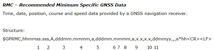
04/08/2018 at 19:35 • 0 commentsAnother vital sensor for MagiLog is GPS. With GPS we'll be able to get references for position and velocity/heading. Additionally it offers two timing features that I might find useful. GPS logs have an accurate timestamp and most GPS modules have a 1PPS output that can be extremely accurate. The GPS module I had originally chosen was the Skytraq Venus638, as it offered the highest refresh rate I could reasonably find and it also had very good reviews. It has a 20Hz update rate and 2.5m accuracy. It communicates over UART and uses structured payloads for data transfer. It has since been replaced by the Venus838 which offers 50Hz update rates. I'll move to that sensor once I start building boards but for now the 638 will suffice. The 638 uses the NMEA 0183 standard and has a few different standard data formats. The main one we're interested in is the RMC message.
![]()
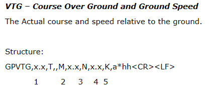
Another message I'm thinking of using is the VTG message. The reason I'm considering it is that it gives us speed in km/h in addition to knots, that means we should be able to get a 1.85:1 improvement on ground speed resolution.
![]()
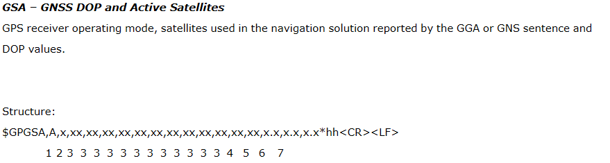
During the dev phase another message that will be useful is the GSA message which will provide us the GPS DOP, with this data we can test different antennas and start to collect data on accuracy in various conditions.
![]()
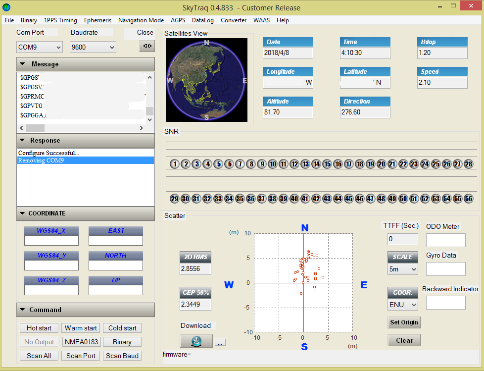
I first started trying to interface with the sensor using my Bus Pirate, and while I was able to get it to stream data to terminal, I was having difficulty writing to the device to change parameters. I then tried to interface to the GPS over a COM port using the manufacturer supplied application.
![]()
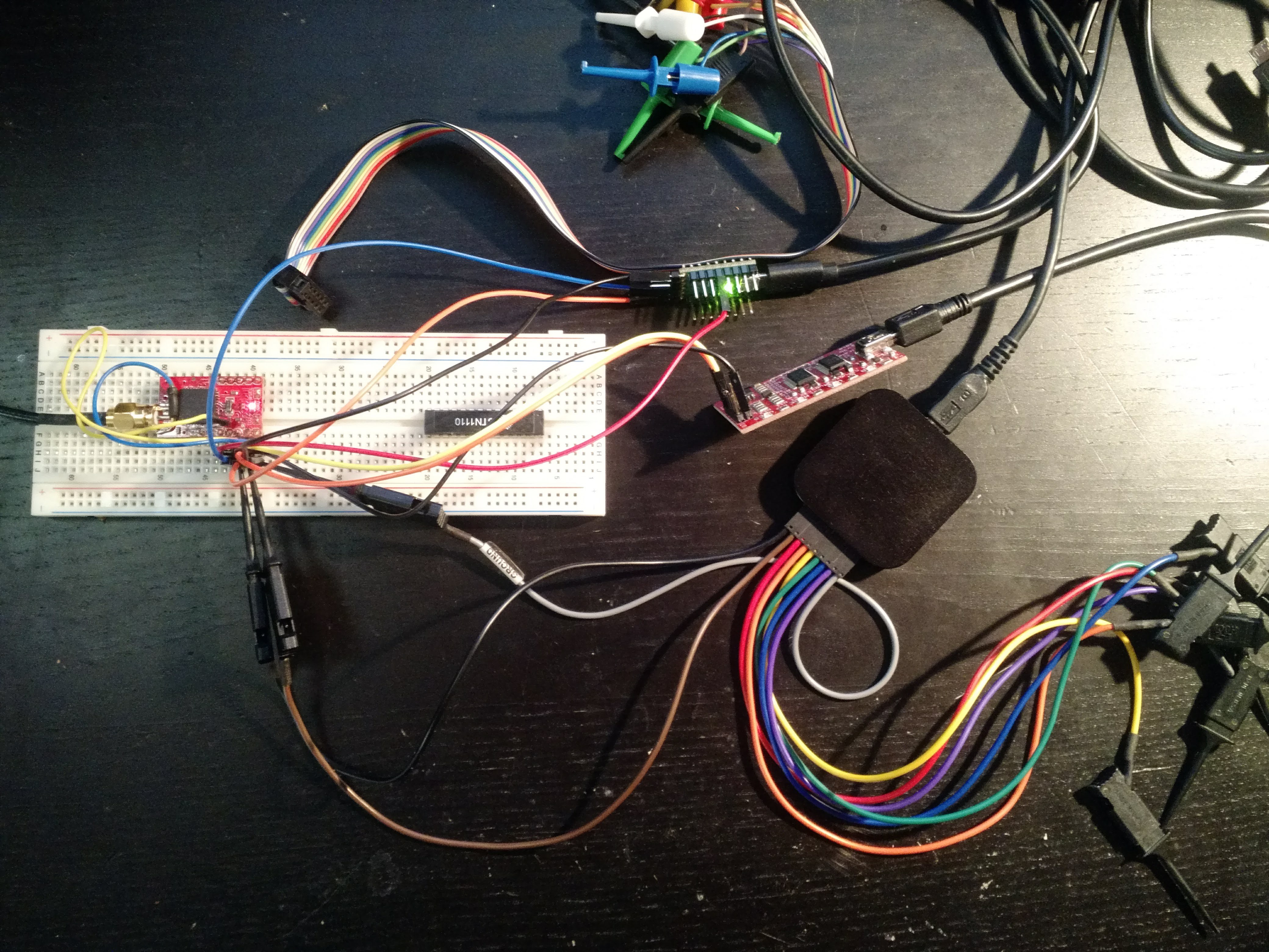
Using this connection method everything was working fine. I needed to dig in a bit more to figure out what could be going on. To do this I used my Saleae (Original) Logic. Connecting it in parallel to the Bus Pirate and Pololu adapter I was able to compare the two to start trying to debug what's going on.
![]()
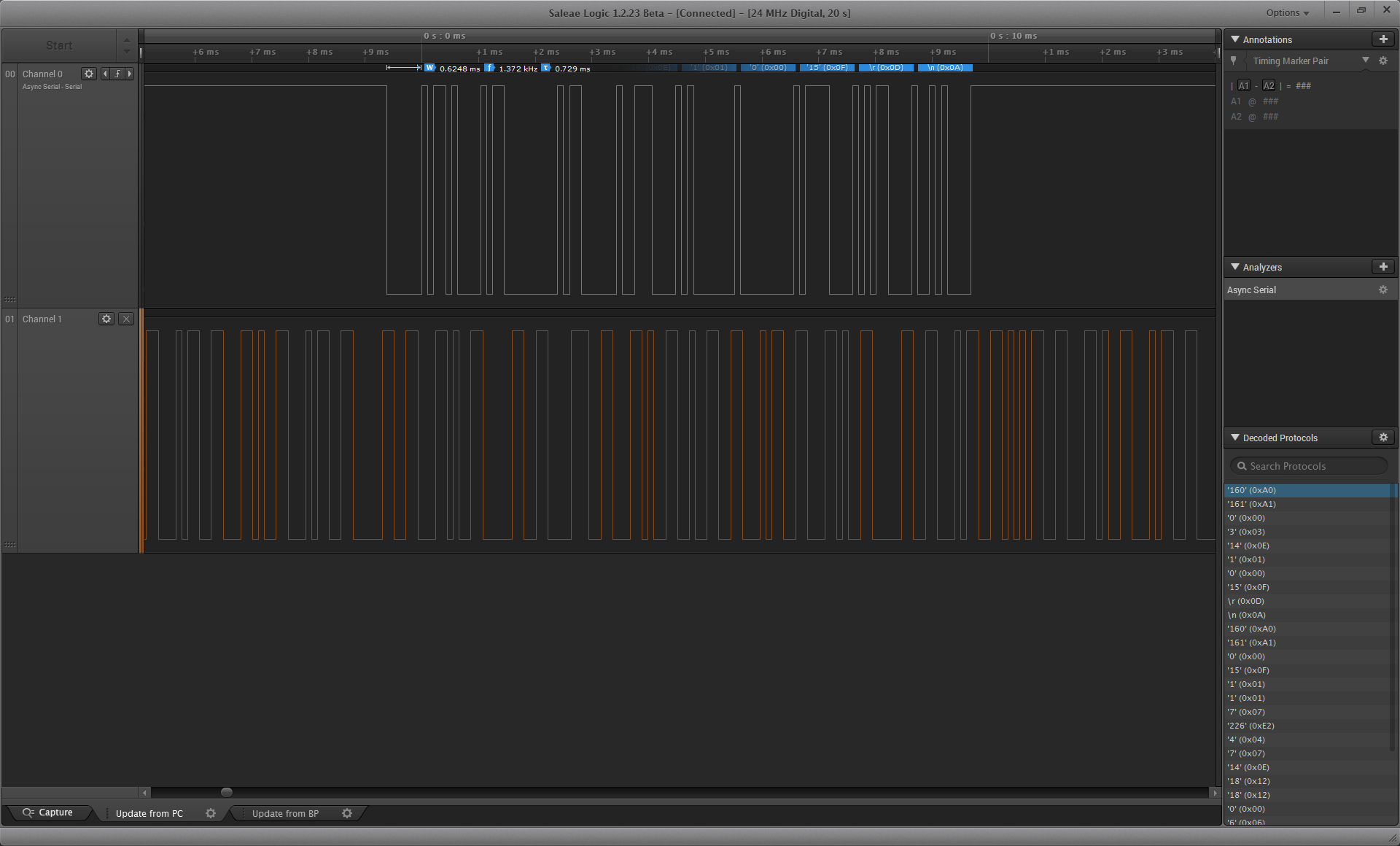
Here's the log for the working Pololu communication:
![]()
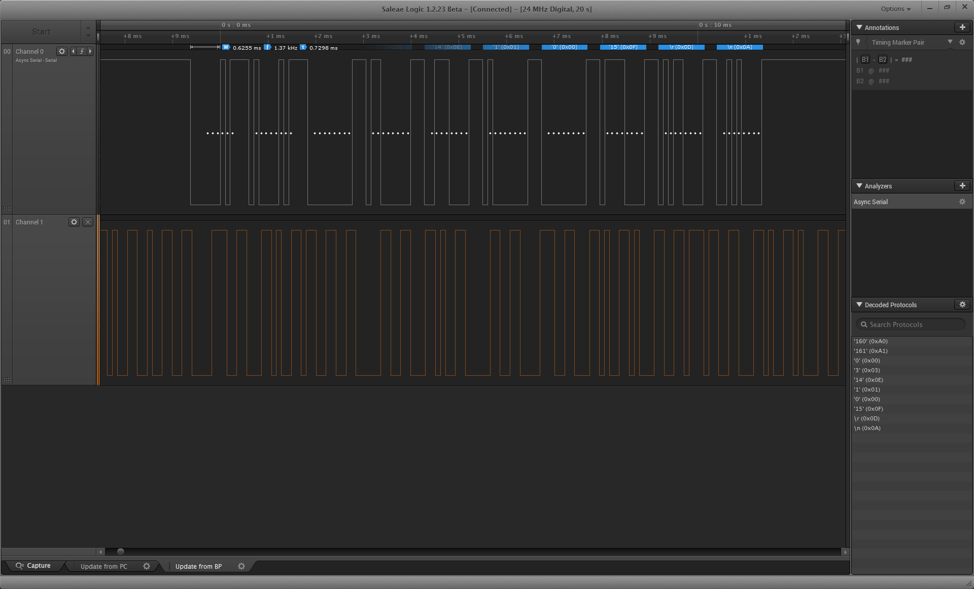
And here's the Bus Pirate message:
![]()
As you can see, the timings are very similar (within a normal margin I'm pretty sure), and on the lower right hand side you can see that the first message sent, which was the change refresh rate command, was the same in each case. So right now I'm a little stumped, I'll keep probing around and post an update with more details and the solution to my woes once I've solved the riddle.
-
MPU-6050+Compass (9-axis IMU)
04/06/2018 at 21:33 • 0 commentsOne of the most important data types I'll be logging is inertial measurements of the car. As our logging rate will be higher than the GPS update rate we need to use IMU data not only for its own purposes but to interpolate between GPS updates. There are a few options for how to merge the two, but I'll likely go with a Kalman Filter.
The IMU unit I originally specced was the MPU-6050, in particular the official eval board with an included AKM compass for 9 axis data. In retrospect I should have selected the MPU-6000 at the time as it has an SPI interface that is both easier to use than I2C and does not require me to make an additional protocol hardware block for the FPGA. In the time since I purchased that board Invensense (Now owned by TDK) has come out with an upgraded version called the MPU-9250. The 9250 removes the need for an external compass and comes with an SPI interface. Sparkfun makes a breakout board that's around a quarter the cost of the official dev board so I'll likely end up picking one of those up.
In the meantime I'll use what I have to get familiar with the register system and the general I/O workflow of using this line of sensors.
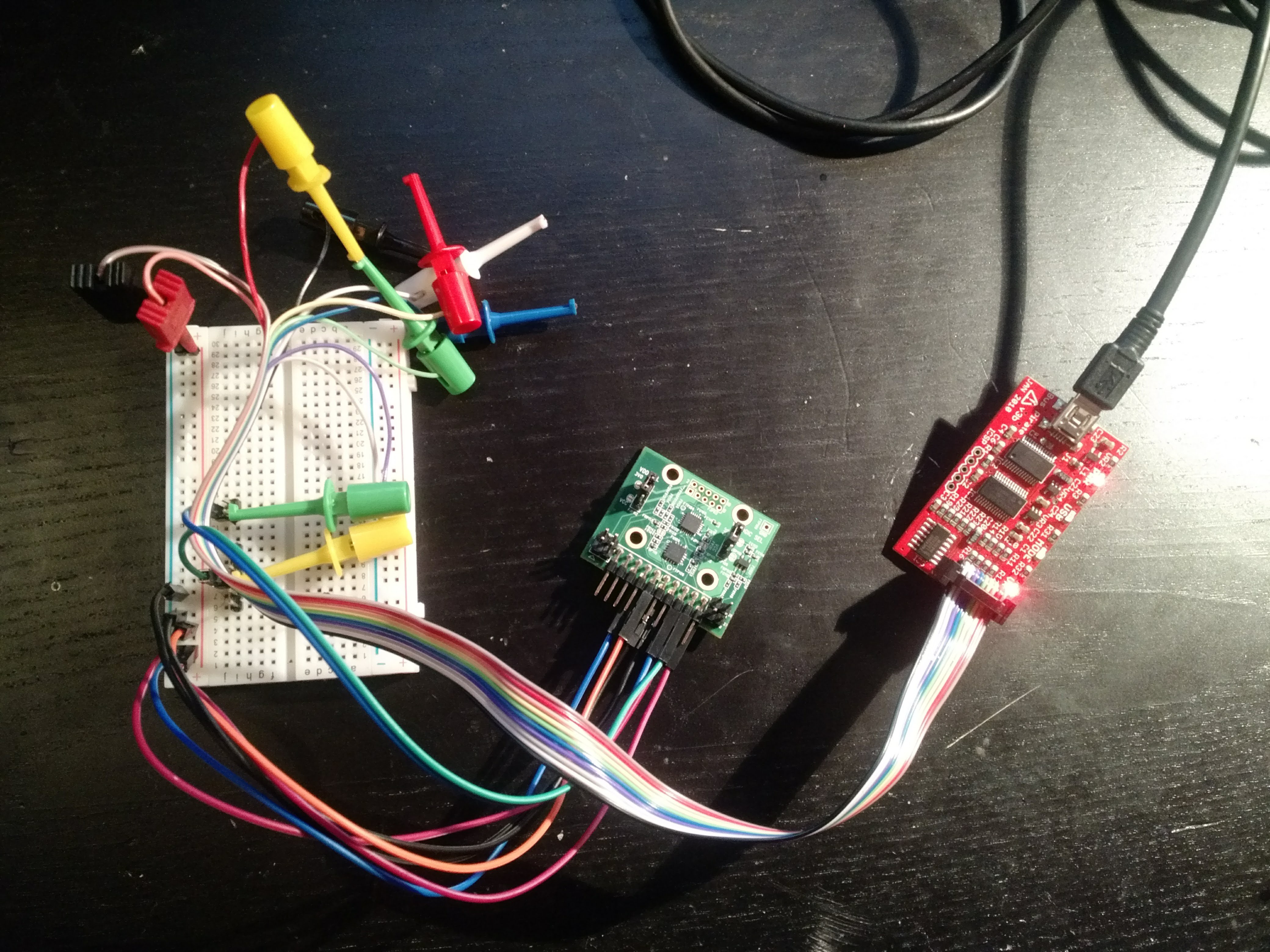
The tool I'll be using to interface with most peripherals during this initial dev phase will be the Bus Pirate, which you can think of as a kind of multitool for serial based communication. To hook up the eval board to the bus pirate we make the following connections: (You'll want to be careful that you use the right hookup guide for your Bus Pirate version. Use "v" to confirm)
MPU VCC -> BP 5V
MPU 2x Gnd -> BP Gnd
MPU LDO_en -> BP 5V
MPU SDA -> BP MOSI
MPU SCL -> BP CLK
MPU FSYNC -> BP Gnd
MPU Int_i -> BP Gnd
BP 3.3V -> BP Vpu
![]()
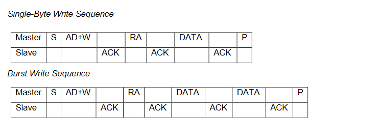
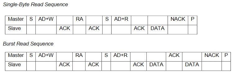
Before diving in completely I recommend you familiarize yourself with the communication protocol. It's explained in the MPU-60X0 datasheet.
![]()
![]()
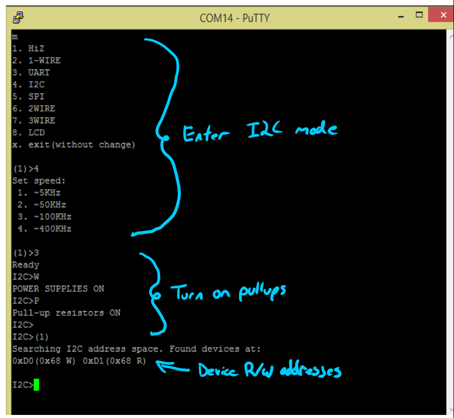
Once you have everything all connected fire up your preferred terminal program and connect to the bus pirate over a COM port. From here first enter m to open the protocol list and then 4 to select I2C. Once you finish up with the options turn on the power supplies and the pull up resistors to finish configuring the Bus Pirate for I2C. Run the I2C scanner macro "(1)" to make sure that we are picking up that the device is connected to the bus.
![]()
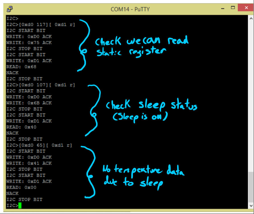
From here check to see if we can read a static register like the "Who Am I" register. Once we have confirmed the connection we check the sleep status to see it has powered up in sleep mode, followed by confirming that data out registers are still empty.
![]()
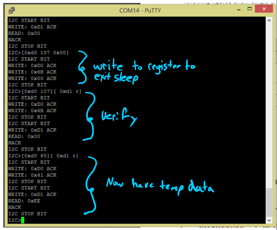
We then write to the power management register to turn off sleep and verify that our settings have taken. Once that's done we can read any of the data registers to get the most recent data from that set.
![]()
I'll need to keep playing around with this and start to think of the easiest way in hardware to combine two 8-bit frames into one 16-bit number. Both SPI and I2C use 8 bit numbers so we'll need to read from two adjacent registers to get the entire number. I also need to figure out the specifics of the data fusion and where that actual computation will be taking place.
-
Janky, but functional
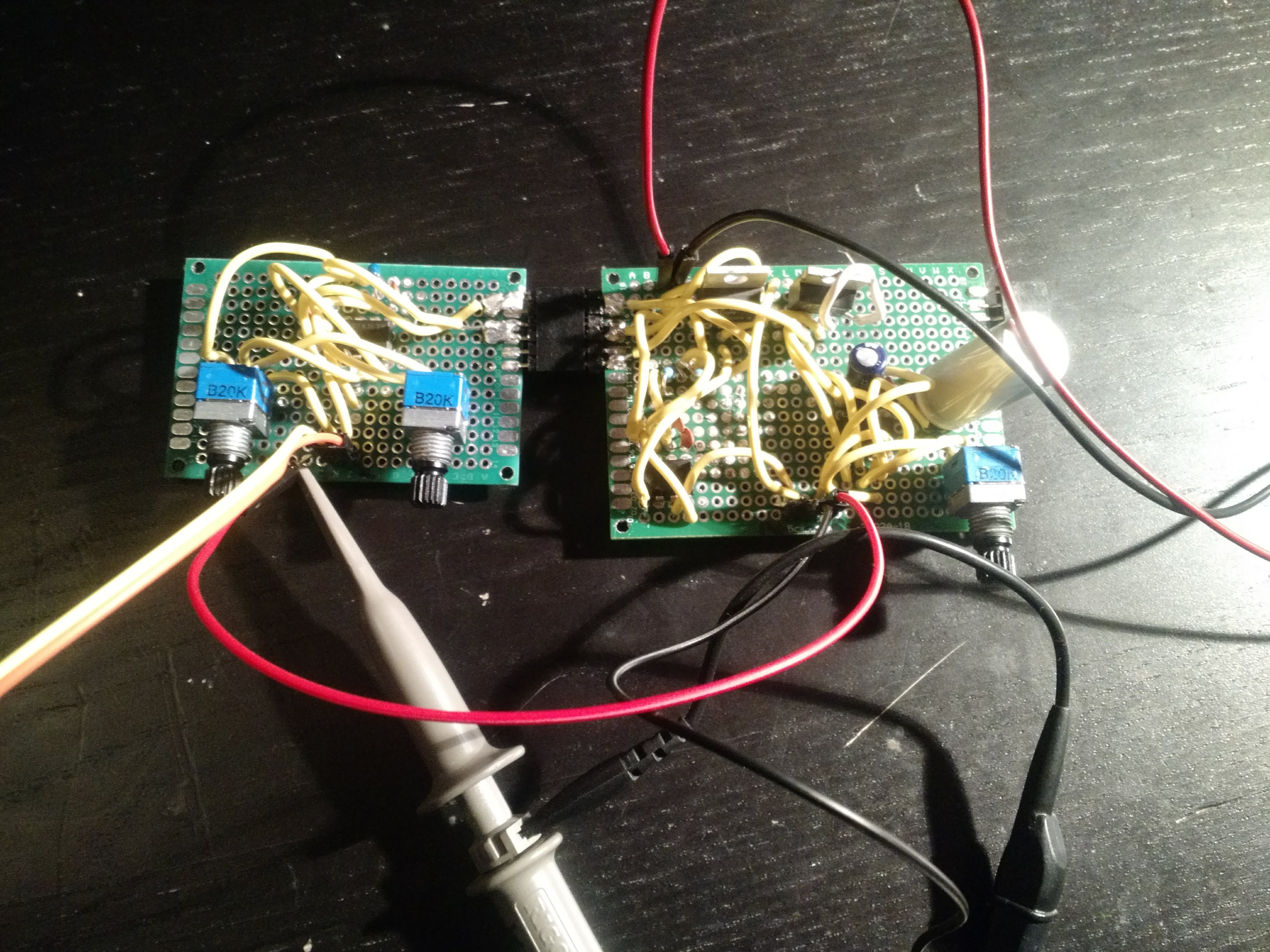
04/04/2018 at 05:05 • 0 commentsI finished up the analog and digital simulator perf boards this evening. Finally, everything seems to be working.
![]()
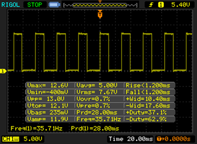
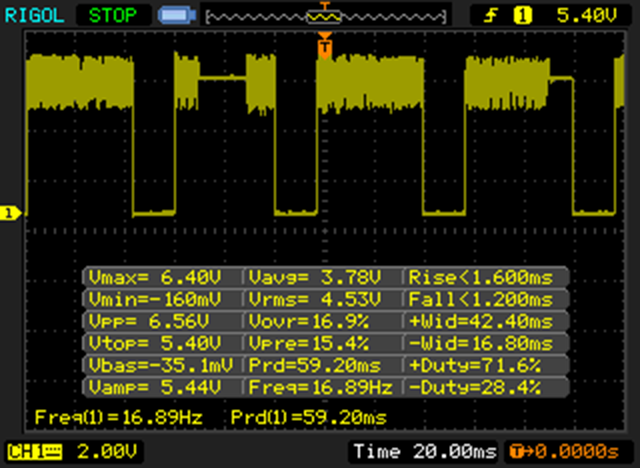
Once again there's a few discrepancies from Spice to reality. At the slowest setting we aren't quite getting down to 30 Hz.
![]()
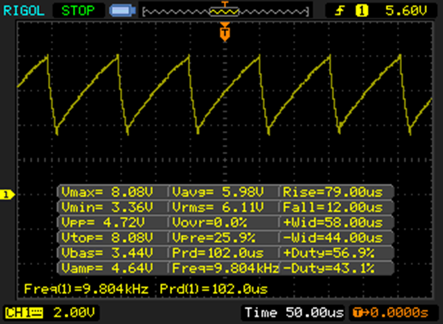
On the fastest setting we're getting about a 50% higher frequency than expected but it looks like absolute garbage. Turning it down to ~6KHz gives us a workable waveform.
![]()
There's another weird bug that I'm not sure about. I can only bring down the output voltage to ~6V. The signal gets very degraded (Duty cycle drops and a bunch of noise appears), and below that value the 555 fails to oscillate at all. I'm not sure what the root cause of this is as the amplitude adjustment shouldn't affect the input voltage into the threshold capacitor. If anyone knows what's going on please give me a hint on how to fix this.
![]()
EDIT: Fixed! Turns out I wasn't paying enough attention and reversed a couple leads on the voltage divider. I now get the full range of 0-12V for Vmax. -
Hello World
04/03/2018 at 23:02 • 0 commentsOver the last couple days I've started getting into and learning ASF for Atmel Studio. ASF is a software framework that kind of sits between something like Arduino and raw C. The documentation is pretty good so I'm making decent progress. I started coding on the XMega and got clocks, RTC and GPIO up and running. Made a short program to cycle between two blinking speeds when a button is held down.
Next up is to get familiar with how ASF handles interrupts and to figure out how to use the event controller to schedule tasks. If anyone knows some good resources other than the ASF docs please let me know!
-
Digital In
04/03/2018 at 04:24 • 0 commentsOriginally I had planned on having 10 total digital inputs but after doing some more research I think a better configuration will be 12 total inputs with 2 dedicated to tachometer inputs; I'll explain what I mean later in this log. The reason for moving to 12 total is that it fits well with using 2 non-inverting hex buffers as the buffer for the digital in. This will let us accept 5-15V inputs without worrying about blowing anything. As the name suggests, each buffer has 6 inputs and outputs. Unfortunately I only have inverting hex buffers but luckily as our simulator will have a 50% duty cycle we can invert the signal coming in without worry. That said though, for the final MagiLog PCB I'll want to spec out proper non-inverting buffers.
As I learned doing #Honda OBD1 Digital Tachometer some cars have really janky tach signals. Because of this I don't want to commit to trying to accommodate them all in a single circuit. To get around this, the tach inputs will have 3 total pins each. One is the expected data in pin, but we will also include a power and ground line. This lets us put a filter inline with the cable to convert non-square-wave signals to a square-wave we can read easily.
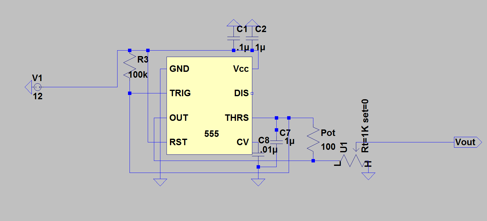
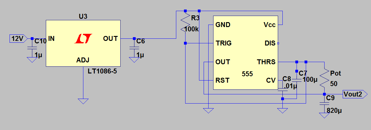
For the simulator we want to be able to simulate a wide range of frequencies with an adjustable Vmax. To do this I've chosen to use a modified version of the 555 timer circuit used to simulate the analog sensor inputs. Note the additional pot and changed threshold capacitor value, and the addition of the recommended decoupling caps.
![]()
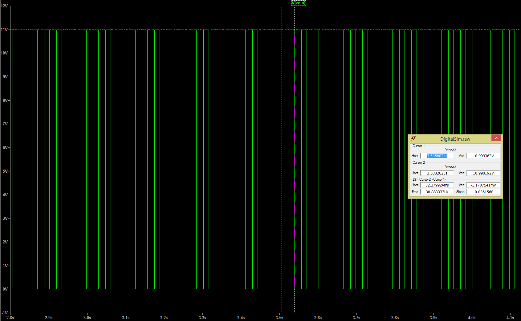
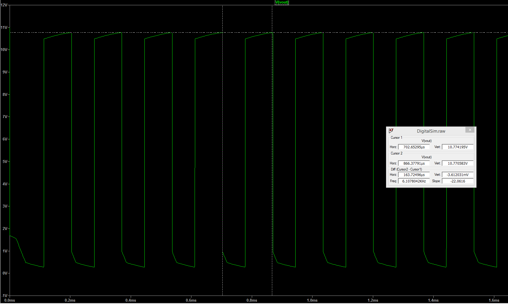
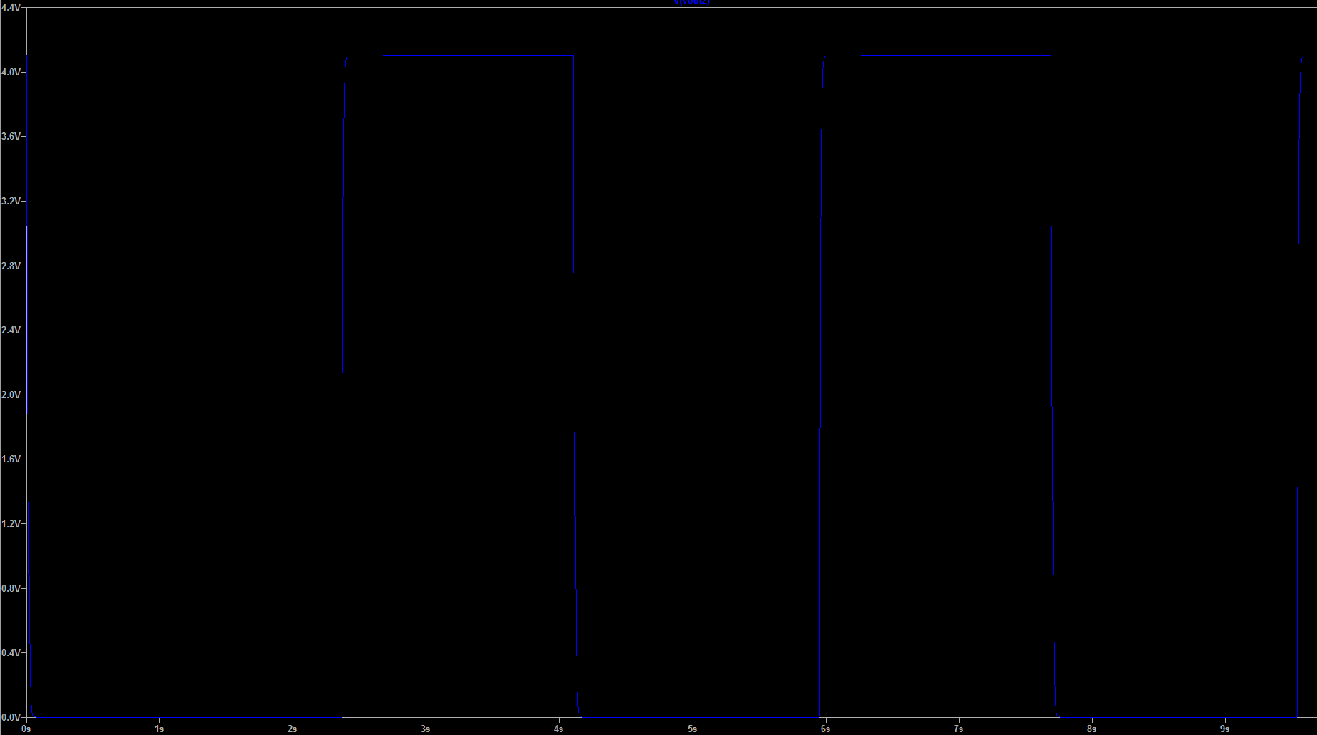
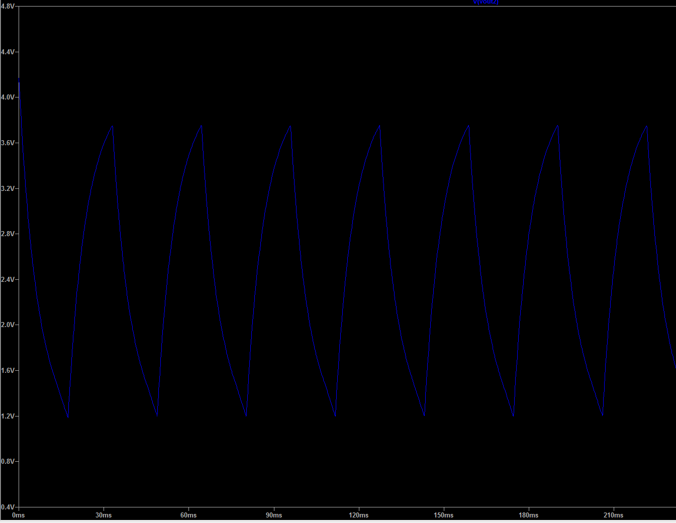
Using this configuration we have full control over the voltage output and we have a usable frequency of around 30Hz-6kHz. Here are the spice outputs.
Slow:
![]()
Fast:
![]()
Next steps for me will be to get the perf board circuit done and make sure it functions how we expect.
-
Analog In Part 4: Perf Board Problems
03/31/2018 at 16:24 • 0 commentsI'm almost done with the perf board prototype but I've run into a few issues along the way. I'll get to those after I go over the progress so far.
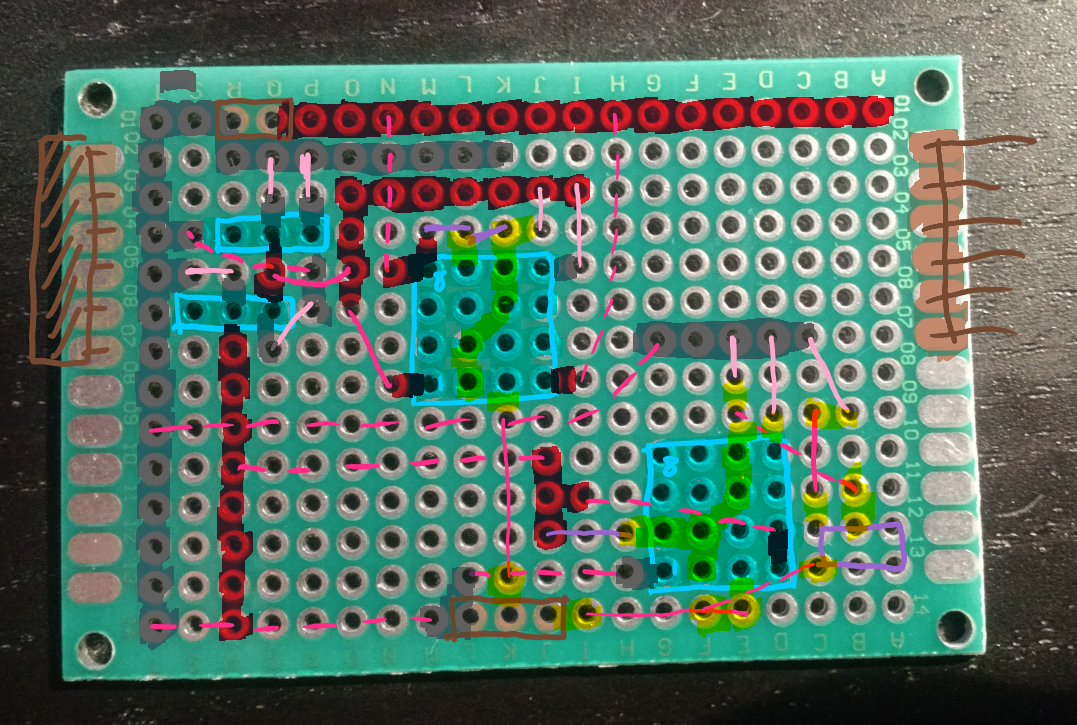
It can't remember the last time I've done a perf board so I was a bit lost at the start. I ended up deciding to take a picture of a few different board sizes and then I used OneNote to annotate components, wires and bridges on top. Here's what I ended up with.
![]()
To solder it I started with the ICs, then I did the passives, then the wires and finally the bridges. Going into things I thought that this approach would give me good access to do all the solders. I was wrong, oh so wrong. Towards the end of the board things got really dicey trying to get to all the pads. I think I ended up either forgetting to do a few of the solders or one of my bridges isn't connecting properly. When I powered the board up, my power supply showed 0 current draw but the outputs were all just noise around 0V. So I'm pretty sure there isn't a major short or else I'd expect there to be some current draw or a puff of magic smoke. I'll need to check it out with a multimeter to try to diagnose what's wrong.
This is the last update for now on the Analog inputs. I'll keep working on fixing the board and for my next log I'll go over the digital inputs of MagiLog.
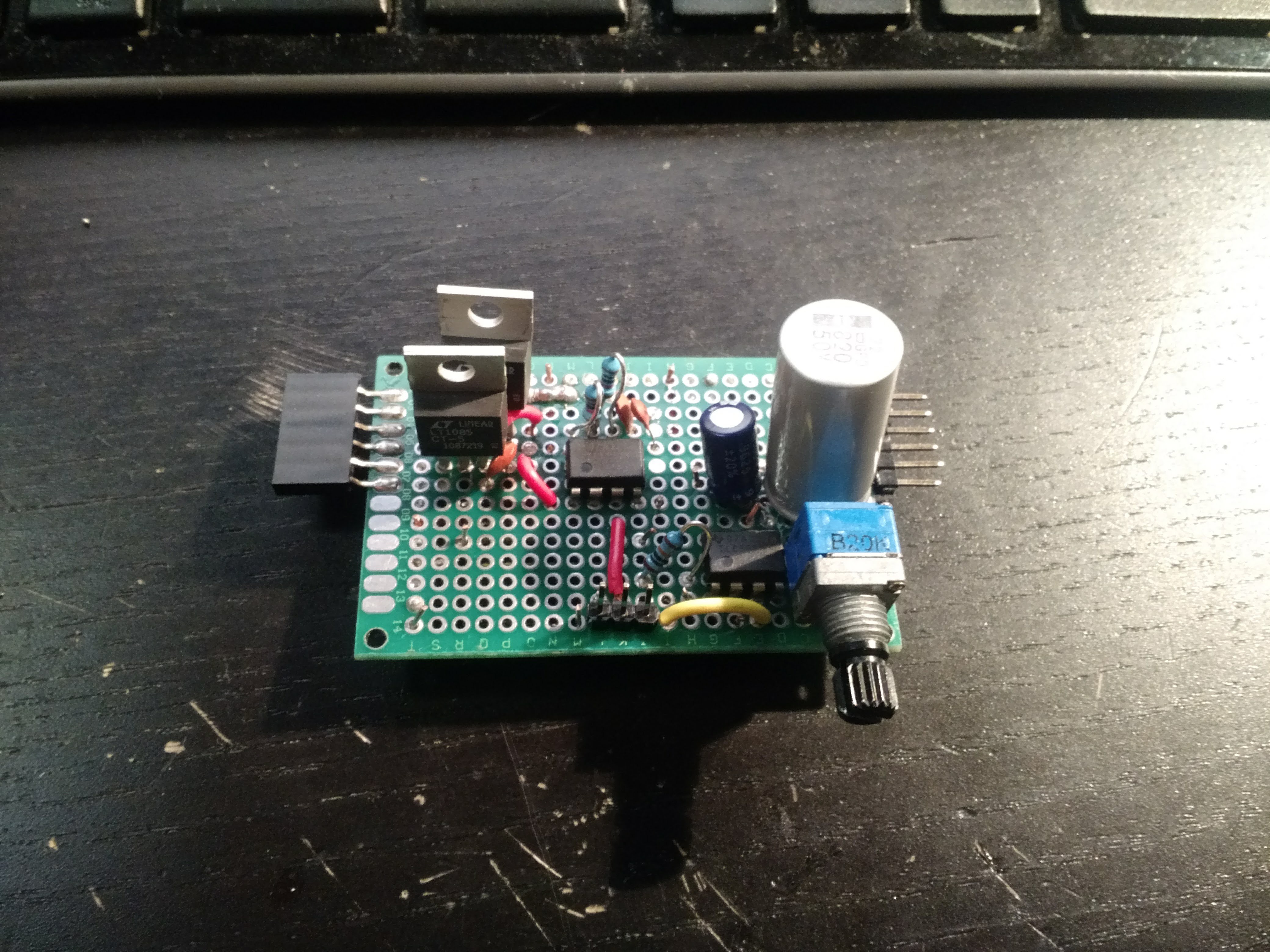
Here's a picture of my first piece of hardware of HaD Prize 2018:
![]()
EDIT: Figured out what I think the issue was on the high voltage output. The 555 I'm using is the LM555 which requires 4.5V to drive, this wasn't replicated by SPICE. What i need to do is swap it out for a lower voltage 555 like the LMC555. -
Analog In Part 3
03/31/2018 at 16:22 • 0 commentsA couple of days ago I was asked the question of "Why not just get all your data over OBD?" and thinking about it I was able to think of a few reasons why I'm happy with my approach.
- Getting a functional prototype will be much easier. Once I have something up and running my progress will accelerate, so this is a good incentive to stick with the way things are.
- Direct sensing will give me a lower latency and potentially higher bandwidth, this will come in handy once I start trying to get as fast of a refresh rate as possible.
- Not every car uses the same OBD standard, and many race cars do not have an OBD compatible ECU at all. Additionally, doing direct sensing will allow MagiLog to be used in non-automotive applications.
All of that said, I'm not discounting OBD altogether, MagiLog will still be capable of it, but direct sensing will be heavily encouraged as the primary data source.
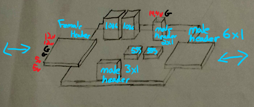
For the simulator side of the project, I'm aiming to create a modular system to allow me to mix and match which functions I can test at once. One of the modules will contain the power management and from there supply all the other modules with 12V and 5V. I ended up sketching a rough idea of what I want it to look like:
![]()
The side headers will allow me to daisy chain modules and all of the outputs will be towards the front of the boards.
As I mentioned last update, the first module I'm making is the analog input simulator. This module will have 2 outputs, a noise 12-14V output replicating a dirty automotive power rail and a 0-5V oscillating output to represent a sensor output.
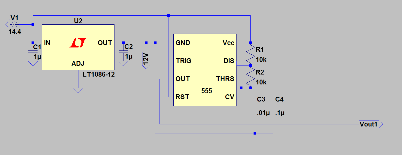
Both circuits are based off of 555 timers. For the HV circuit we set VCC to +14.4V and set the 555's ground to the 12V rail, this will allow us to get that high speed oscillation between the voltages we are looking for. I selected the resistors to give me a roughly 66% duty cycle.
![]()
For the 5V circuit we leave the discharge pin floating and then power the threshold capacitor with our output. This will give us an exactly 50% duty cycle with the ability to tune the frequency with a potentiometer. I popped a big smoothing
capacitor on the output so that we get some values to read that aren't just 5V and 0V.![]()
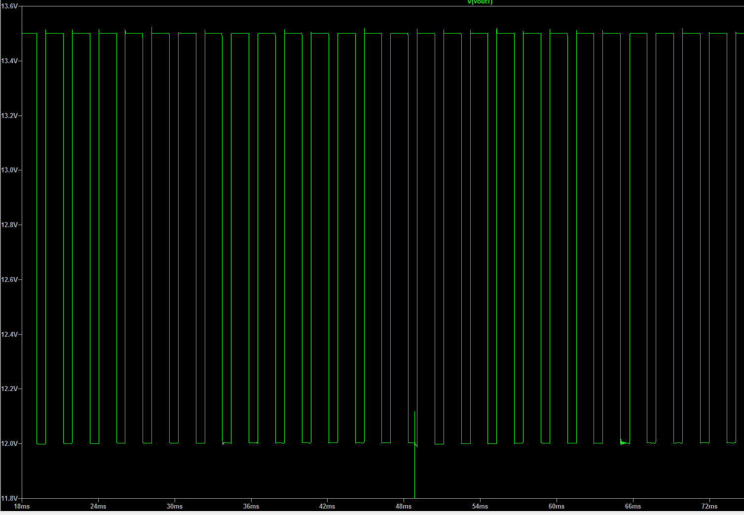
Now that you've seen the circuits, let's go over the outputs starting with the simulated 14V output.
![]()
This is pretty much what we want with a frequency of around 500Hz. That said, I'm thinking of increasing the frequency up to somewhere between 2-5KHz and throwing on a smoothing cap to narrow up the voltage range. Though… I should probably just get a scope measurement from someone's car to make sure this output isn't literal trash.
Thankfully I'm more satisfied with the LV oscillator. Here's the graphs simulating inputs at the low and high frequency bounds.
Slow:
![]()
Fast:
![]()
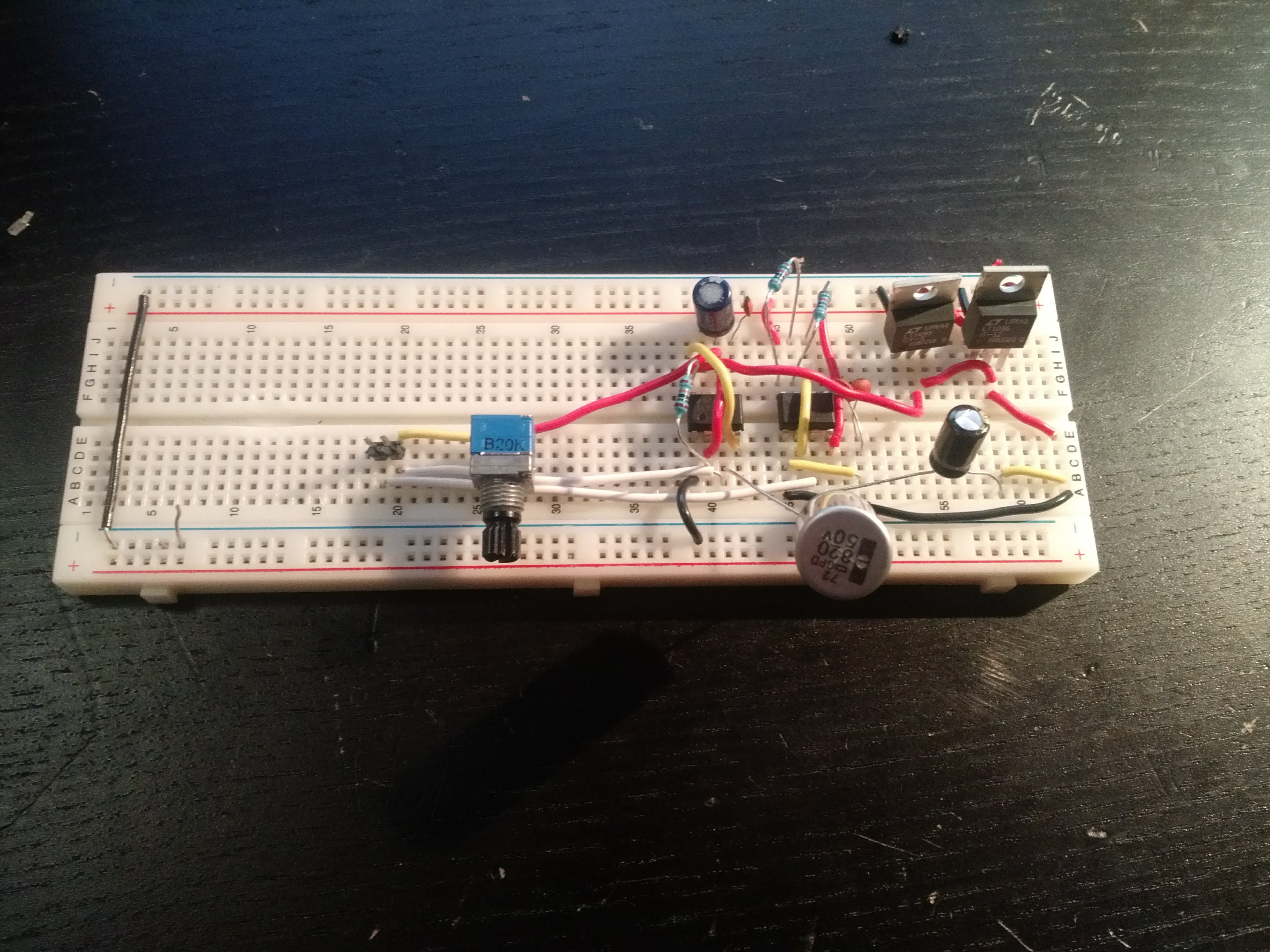
So finaaaally we to building some actual hardware. As is tradition, we start off with a breadboarded version to test out.
![]()
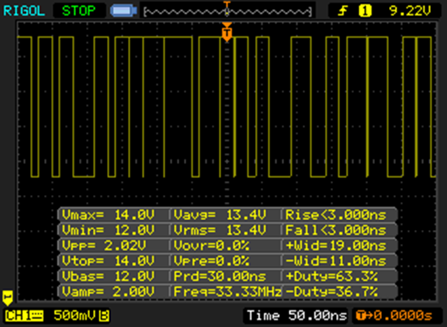
Here's what it outputs.
14V:
![]()
It’s close, but if you look carefully you'll see the frequency is somewhere greater than 33MHZ (I'm pretty sure this was my scope telling me it's unhappy), after a few cap taps we were free of this issue and all was well.
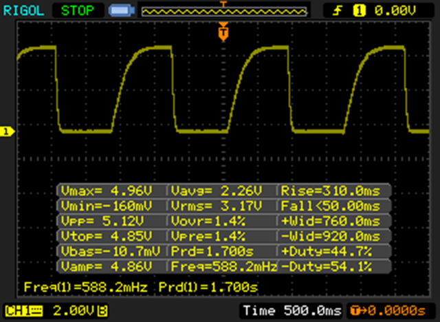
Here's the 5V output on the slow setting:
![]()
There's some difference in the waveform shapes, but the voltage range and frequency are nearly bang on. Hooray!
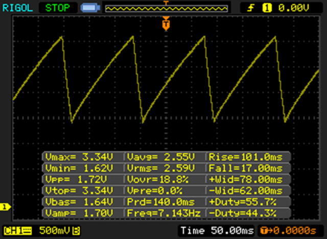
For the fast setting here's the result:
![]()
Once again things look pretty good! Though one weird thing I noticed was at the fastest setting we were only getting around 7Hz, we'd expect to get up to ~30Hz. Not a huge deal and hopefully it goes away once things are in a more robust PCB.
This is getting a bit long, so I'll split it up and finish up Analog in one more log.
-
Analog In Part 2
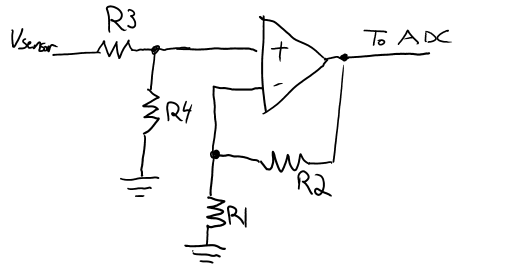
03/26/2018 at 21:47 • 0 commentsThe actual hardware needed to create our input stage and the input simulator is fairly simple. We need to buffer/scale, read, and then extract the values coming from our sensor. Since it seems that we only need 1 ADC input with the ability to read 15V we can group 15 of the inputs into one type of circuit, and the
"high" voltage line into another. As most of the sensors the MagiLog will interface with operate at 5V it makes sense for us to set Vref at 5V as well. This means on the 15V input we need to scale that voltage down to fit in a 5V range. We can do this with a simple op amp circuit. Additionally, we need to buffer
our inputs. This will make our device much better at handling nonnominal input voltages. It also has the bonus of providing a high-impedance sink to whatever sensor we are trying to read. This prevents the ADC reading process from affecting the sensor output. To achieve this goal we will use two variations of
the following circuit.![]()
In this circuit the gain of our output is equal to (1+R2/R1)*(R4/(R3+R4)). Depending on what we need to do we can modify values or remove components. We don't need any gain values larger than 1, so this means that we can make the op-amp portion just a voltage follower. To do this we open R1 and short R2, leaving us just with R3 and R4. In the 5V measurement circuit we short R3 and open R4 meaning we don't need any resistors to read 5V signals. For the HV signals we need to scale 15V to 5V and we accomplish this by making R3=2*R4. One thing to note is since I'll probably end up using the 5V rail to power the op-amps I'll need to make sure I use rail-to-rail op-amps. This means that they will be able to output all the way from V- to V+ (Gnd and 5V).
To do the actual reading of the sensor voltage we use an ADC. The one I originally specced out was a TI ADC128S022. It's a standard 5V, 12Bit ADC with 8 input channels. As a quick sanity check we can compare our sample rate to the specifications. With 8 inputs running at 100Hz that gives us a total sample rate of only 800Hz, in other words we have roughly 100x headroom on sampling. This gives us a lot of flexibility to do things like oversample to increase our resolution from 12Bit to 14Bit. Once the data is obtained, it is clocked out with 4-wire SPI. I'll get into the details of this more once I start working on the HDL to interface with the ADC.
To simulate our car conditions I'll like 2 types of outputs. One output will be ~12V with some noise injected to simulate a dirty car power rail. I'm not too sure how I'm going to do this yet so I'll do a part 3 once I get more research in and an idea down on LTspice. The other output will be a oscillating circuit with a Vmax of 0V-5V and a Vmin of 0V. I'll need to find out what sort of time scales I should be simulating so I'll work on that and get it into part 3 as well.
BTW I found that ISO standard I mentioned in the previous log. It's ISO 7637-2.
-
Analog In Part 1
03/22/2018 at 20:40 • 0 commentsThe first set of inputs we'll be going over is Analog In. Currently I'm aiming to have 8 total analog inputs available to the user, split over two ADCs.
I've done some quick research on what kind of signalling analog automotive sensors normally operate off of and it seems that most operate on <5V. This is nice as it makes interfacing with most ADCs painless. There is however, one "high" voltage source that we'll want to measure, battery voltage. To ensure we can safely measure this, whichever input we assign to battery sensing must be able to survive voltages up to (and possibly higher than) 15V.
Automotive 12V rails are notoriously noisy so in order to get good readings we'll have to employ some sort of filtering or averaging. Let's look at what other sorts of waveforms we can expect to encounter when reading sensors.
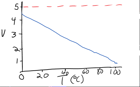
Temperature:
It looks like most automotive temperature sensors are pretty simple. The main T to V function is linear with two special cases denoting a short or open fault. Noted with 0V and 5V respectively.
O2 Levels:
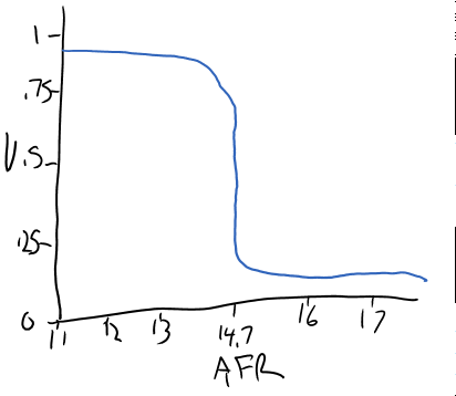
O2 sensors come in two flavours, narrow-band and wide-band. As far as I understand it, narrow-band O2 sensors are the most common type used in OEM applications. They have an interesting property where there is an abrupt change in voltage at the level corresponding to a stoichiometrically balanced air fuel ratio (AFR).
![]()
Due to the abrupt change in voltage, O2 sensors cannot reliably read the ratio beyond a narrow range of values.
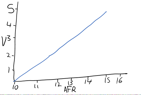
In aftermarket applications where a greater ability to read specific values is desired a wide-band O2 sensor is used. These sensors are usually linear over a wide range of possible AFRs.
![]()
Boost/Pressure:
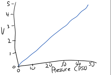
Pressure sensors are also linear. There a few different types spanning different usages. A coolant pressure sensor we'd expect never to have a value below 0 PSI(gauge) however, a boost sensor for a turbo setup would expect to see negative and positive gauge pressures. The details in how these types of sensors map pressure to voltage will need to be studied more in order for us to implement a wide variety of pressure sensors.
![]()
For pretty much every type of sensor we'll be able to read the output without any sort of scaling. This is nice as it'll bring down the board complexity by a fair amount. In the case of the battery voltage we'll have to convert it down into the range that our ADCs can read. We also need to keep in mind that automotive power rails are extremely noisy and can have some pretty extreme anomalies. I can't remember the name, but there's a standards document that outlines the kinds of waveforms that we need to protect against. I'll try to find it and include some of the recommendations in another project log.
In my next log I'll go over the actual ADCs as well as plan out how I'm going to replicate these signals.
-
Plan of Attack
03/14/2018 at 21:59 • 0 commentsSo far I'm thinking the best way to approach this project is to follow 3 main paths of progress:
- Continue researching/learning. There's a lot about the nitty-gritty side of things that I need to build a better understanding of if I have any hope of getting the FPGA interfaces to work. I'll need to go over communication protocols, power supply and how to implement the data transfer efficiently. (for that I'm thinking DMA)
- I'll need to go over all the components I've already specced and/or purchase to ensure that they are what I want to go with. As I mentioned before, a lot of these parts have been EoL'd or have an updated version out. Where it makes sense I'll try to stick with what I already own, but if anything stands out I'll have to start planning around the newer option
- I have to lock down the I/O feature set that I'd like to support. Once I have that, I'll need to build a simulator (I've sold my car since the first round of working on this) in order to debug, test and optimize the various ways I plan on being able to interface with a car. This will also be a good trial run for PCB design as while it'll end up decently complicated, it will be definitely simpler than the PCB used on MagiLog.
Thoughts, suggestions? If I'm doing something stupid, please save me from myself
MagiLog: Open Automotive Datalogging
Developing a full featured datalogger on the cheap