 pablosun
-
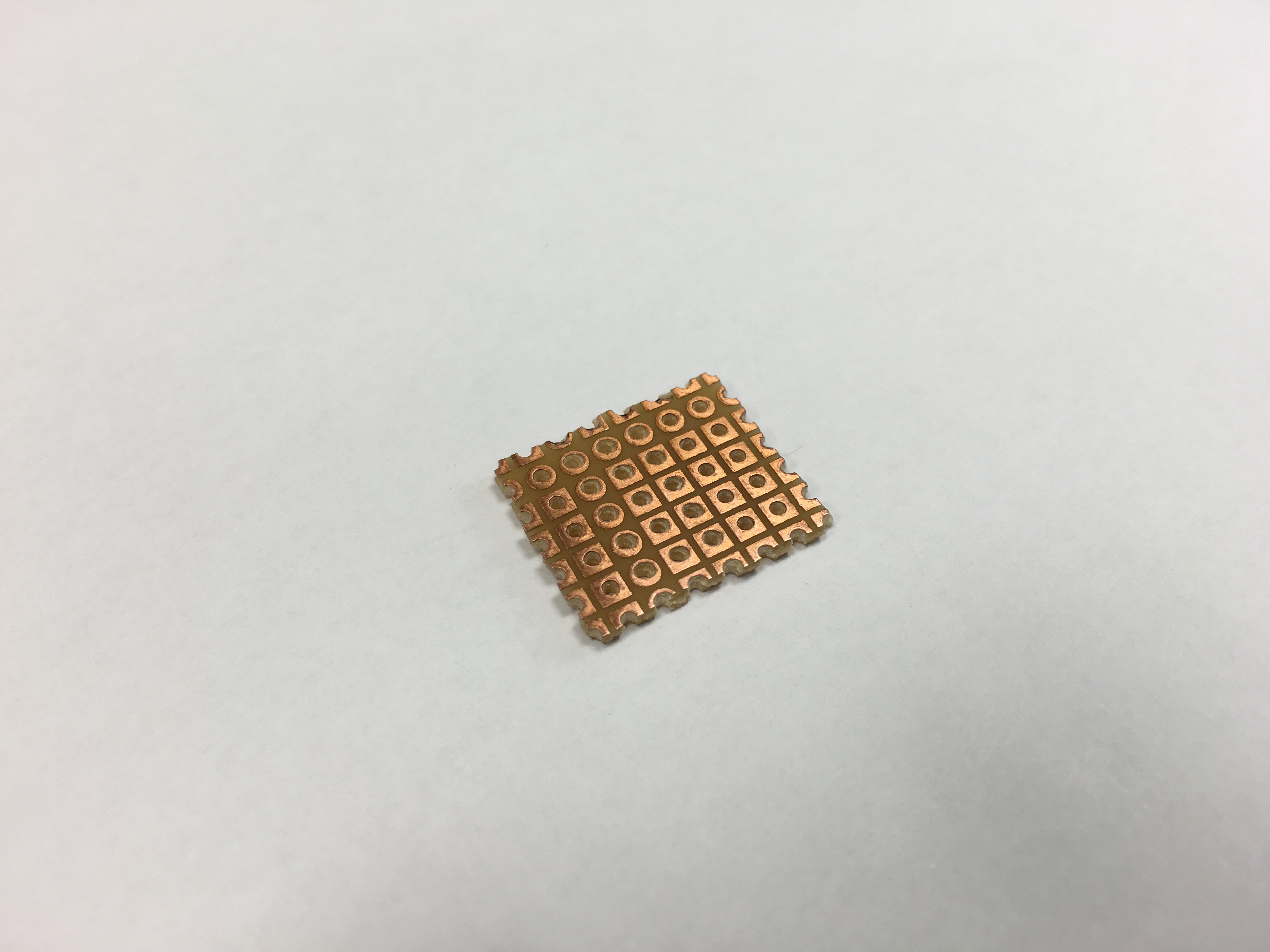
1Step 1
Cut the perfboard into 5x6 size. Note that we use a perfboard with only 1 sided padded.
![]()
-
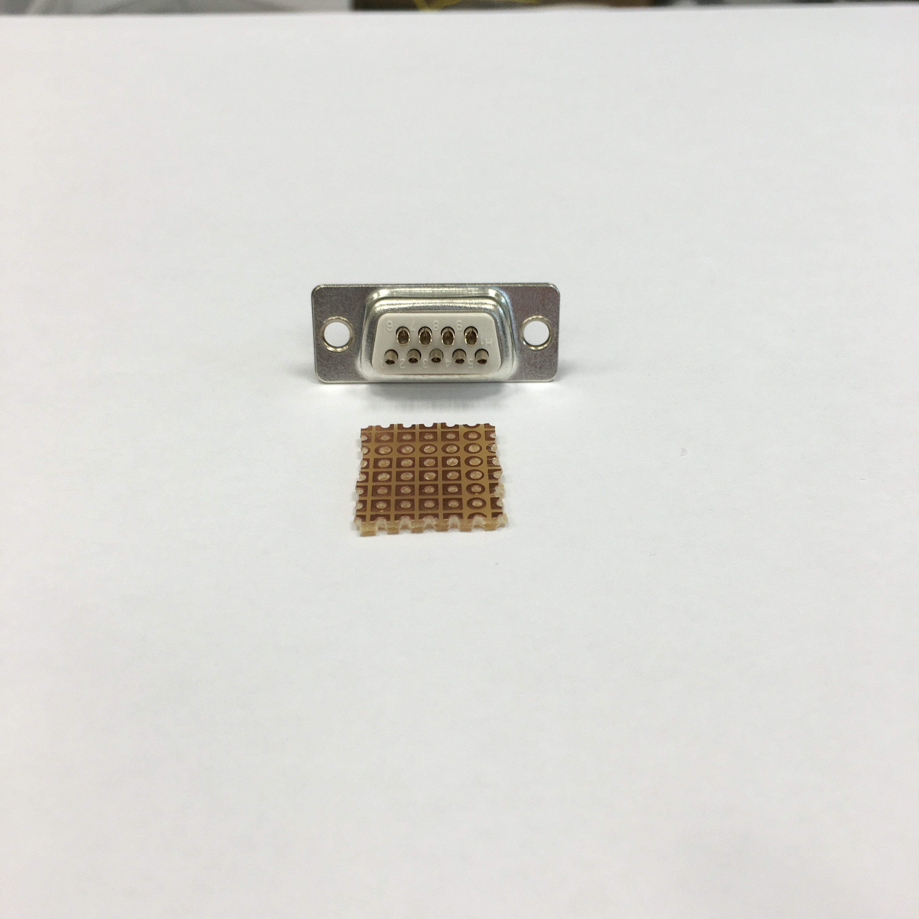
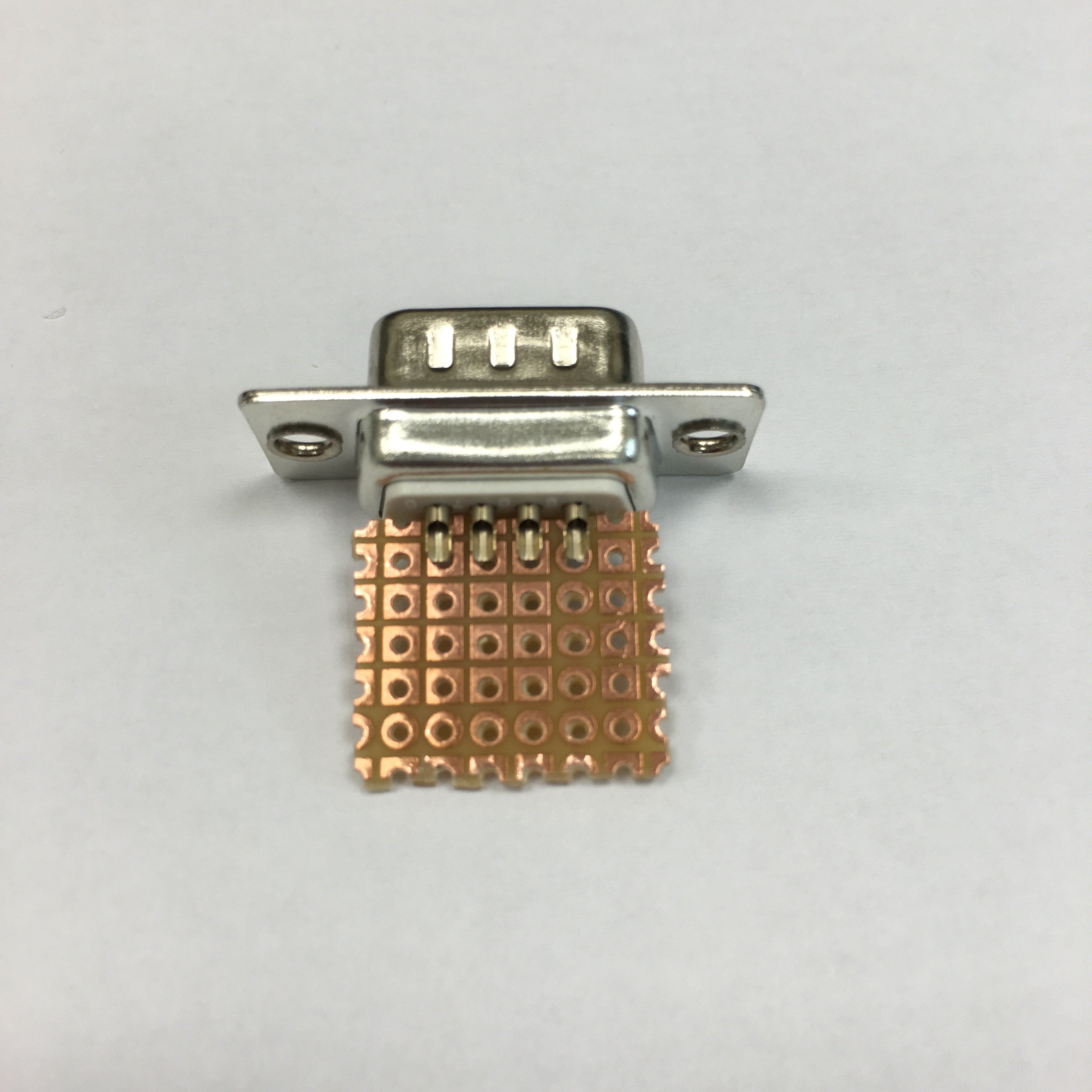
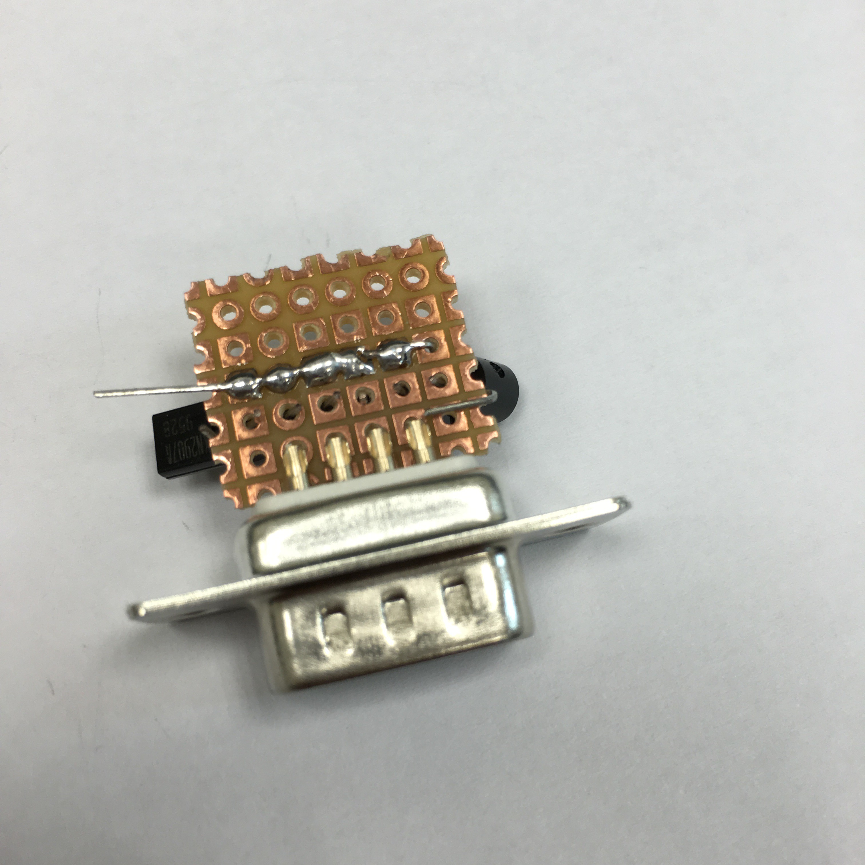
2Step 2
Insert the perfboard between two rows of pins of the DB-9 connector. The copper side of the perfboard should be aligned with the 4-pin side of the DB-9 connector, with 2 pads left on each ends.
![]()
![]()
-
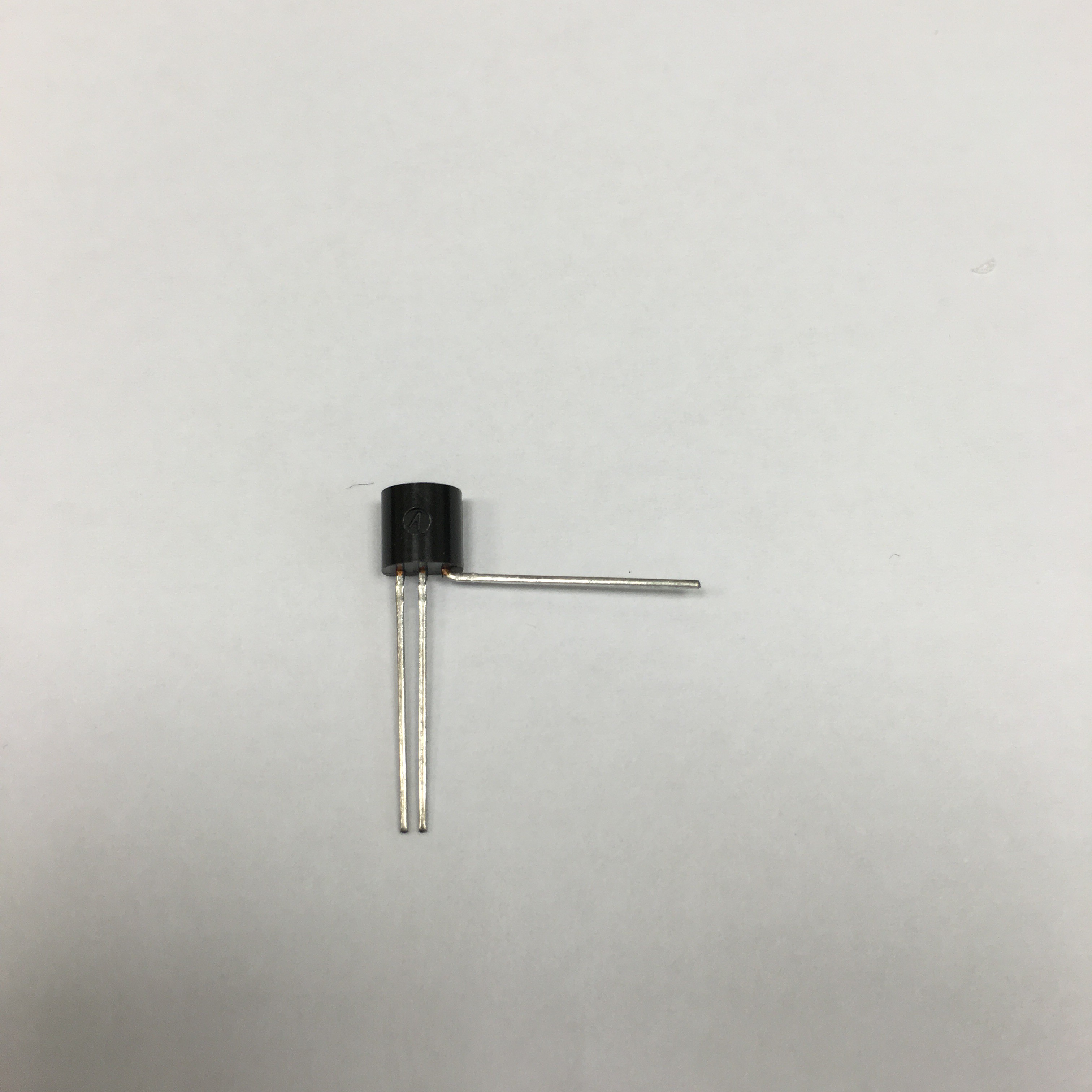
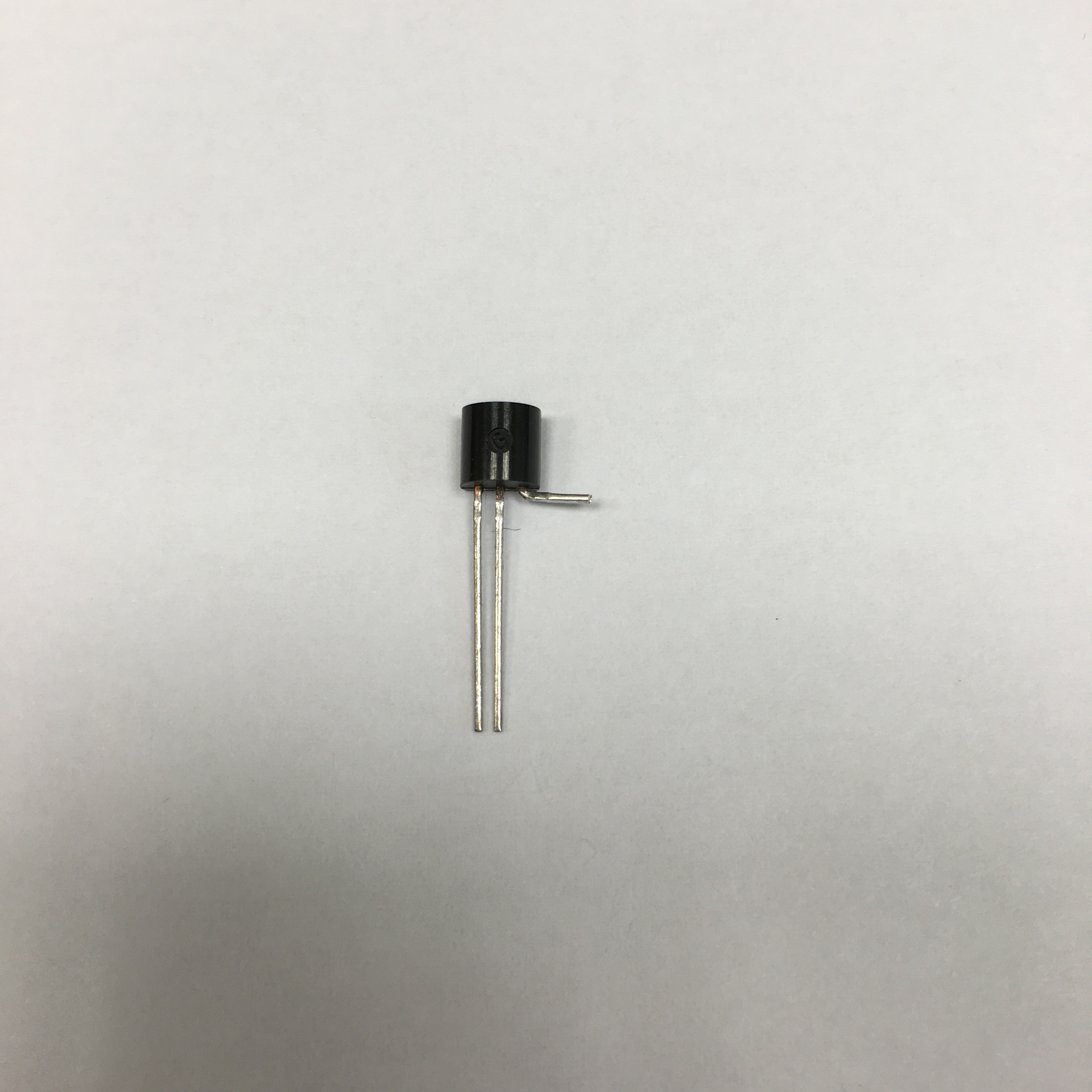
3Step 3
Now we install the PNP transistors. Prepare 6 PNP transistors. Take only 4 PNP transistors, bend their collector pin, and then cut it. Leave enough length to allow us to solder the collector pin to the DB-9 connector pins.
![]()
![]()
-
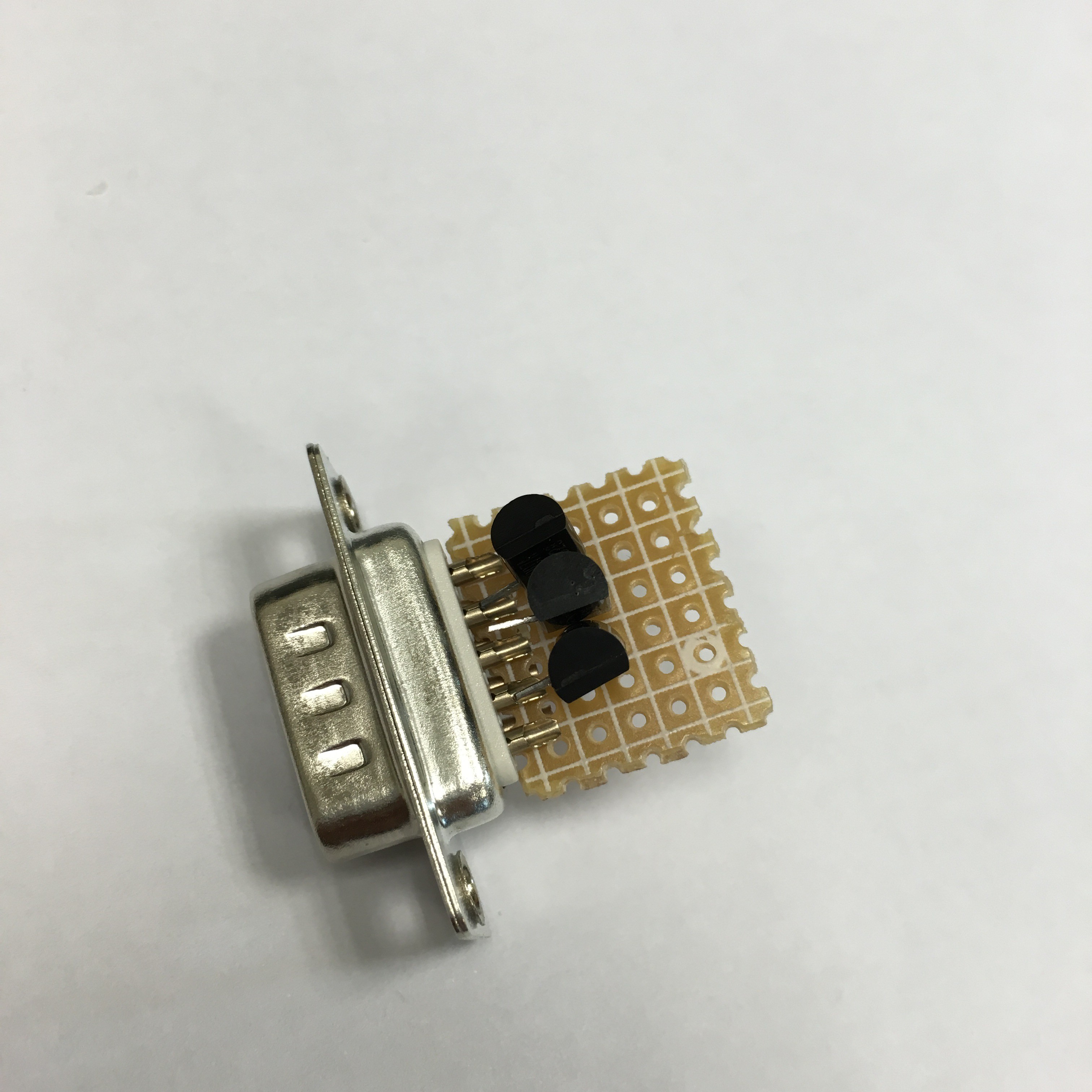
4Step 4
Insert the 4 transistors to the perfboard from the 5-pins side of the DB-9 connector. This is non-padded side of the perfboard in our case here. Align them with pin 2-5 of the DB-9 connector. Leave pin 1 open, as it serves as GND.
![]()
-
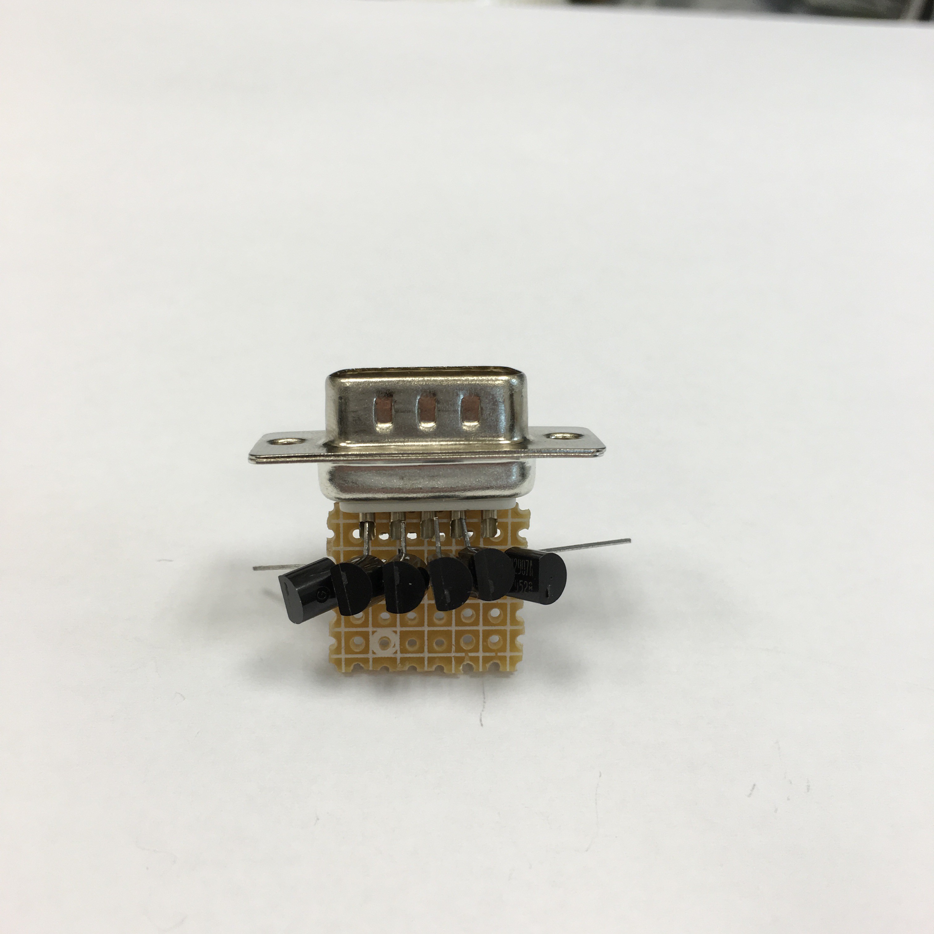
5Step 5
Insert the other 2 PNP transistors(without collector pin cutted) to the both ends of the perfboard.
![]()
-
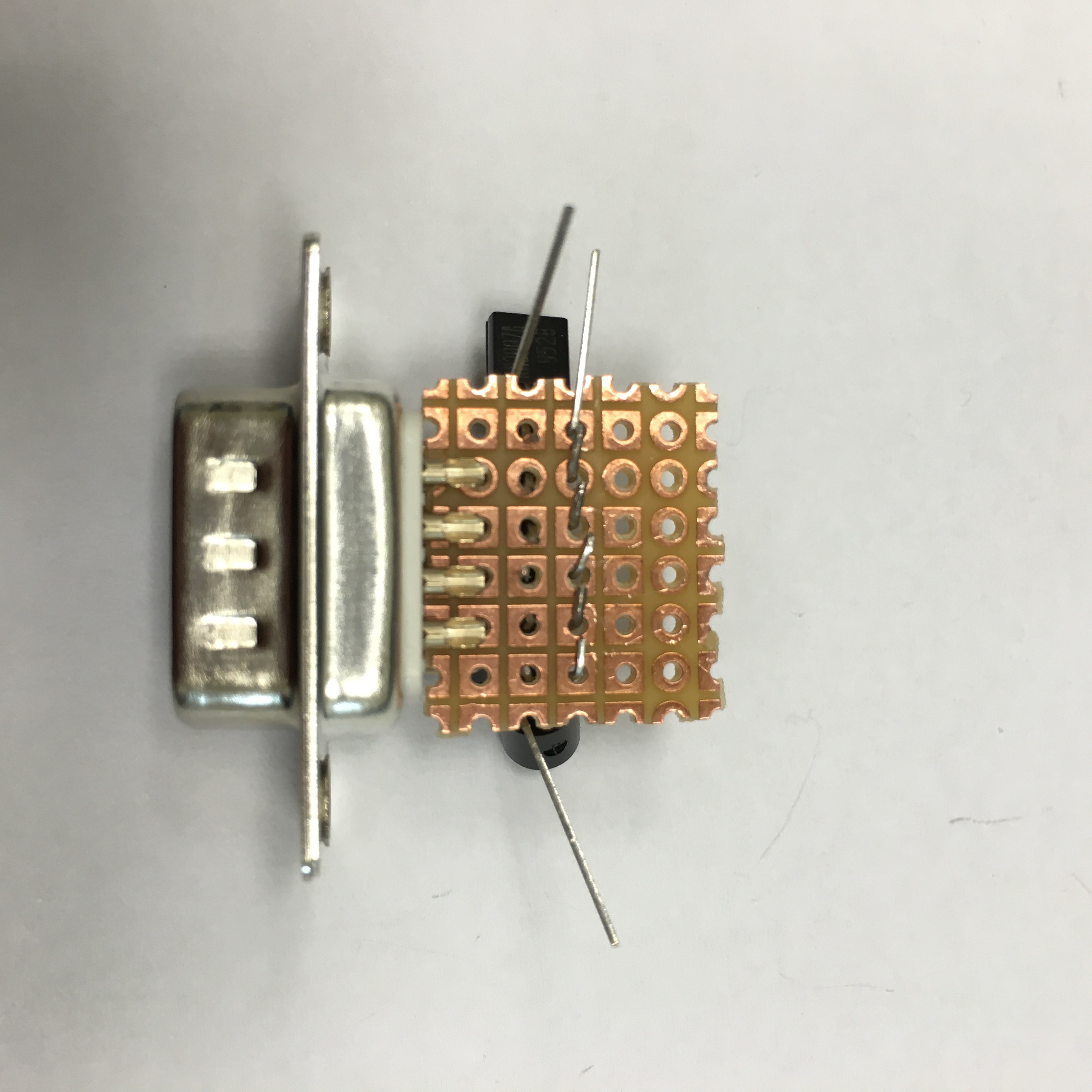
6Step 6
Bend all emitter pins so that they connector together, cut 5 of the emitter pin so they can be soldered to each other. Leave the emitter pin of the PNP transistor that is located near pin 9 of the DB-9 connector uncutted - this will connect as our power input pin.
![]()
![]()
-
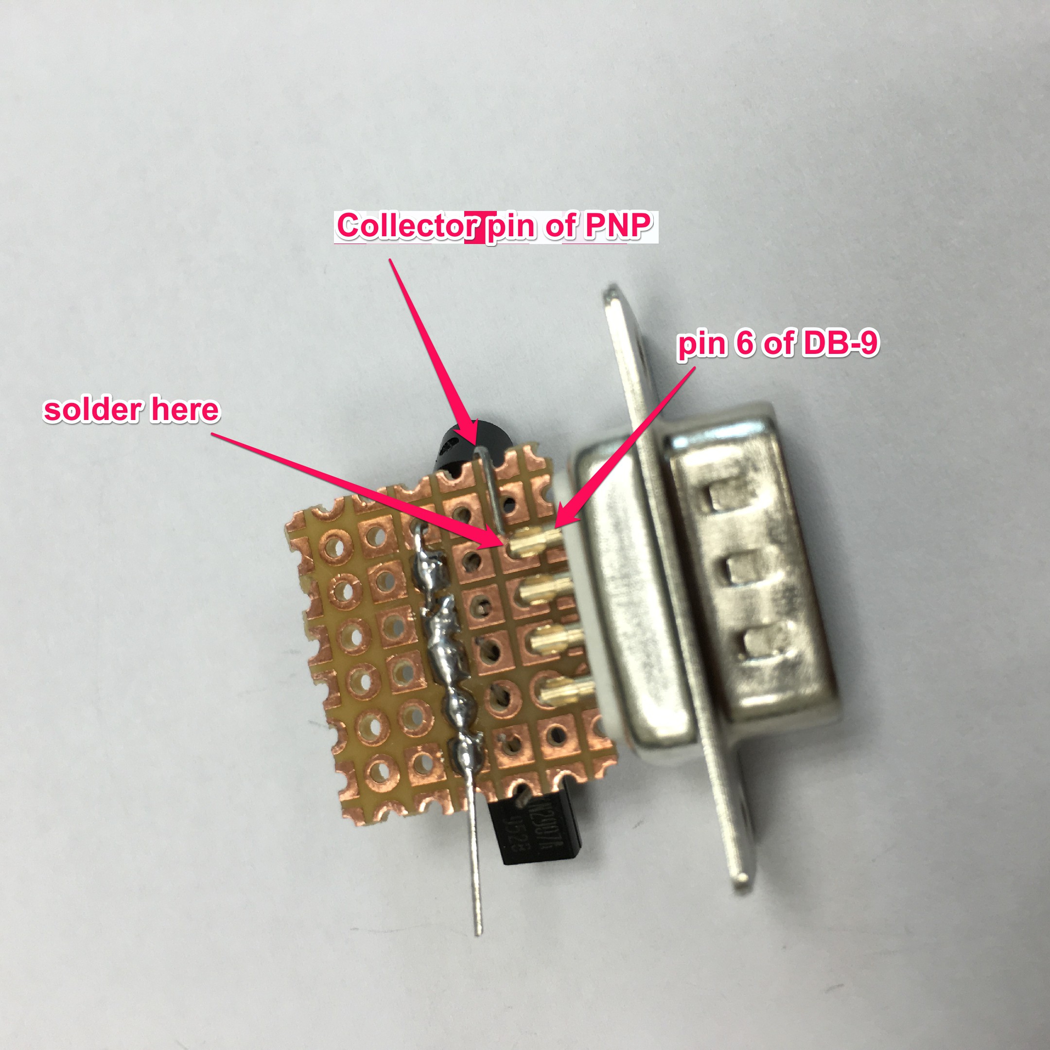
7Step 7
Now we bend the collector pin of the PNP transistors that is located near pin 6 of the DB-9 connector. Bend the pin towards the pin 6. Solder it.
![]()
-
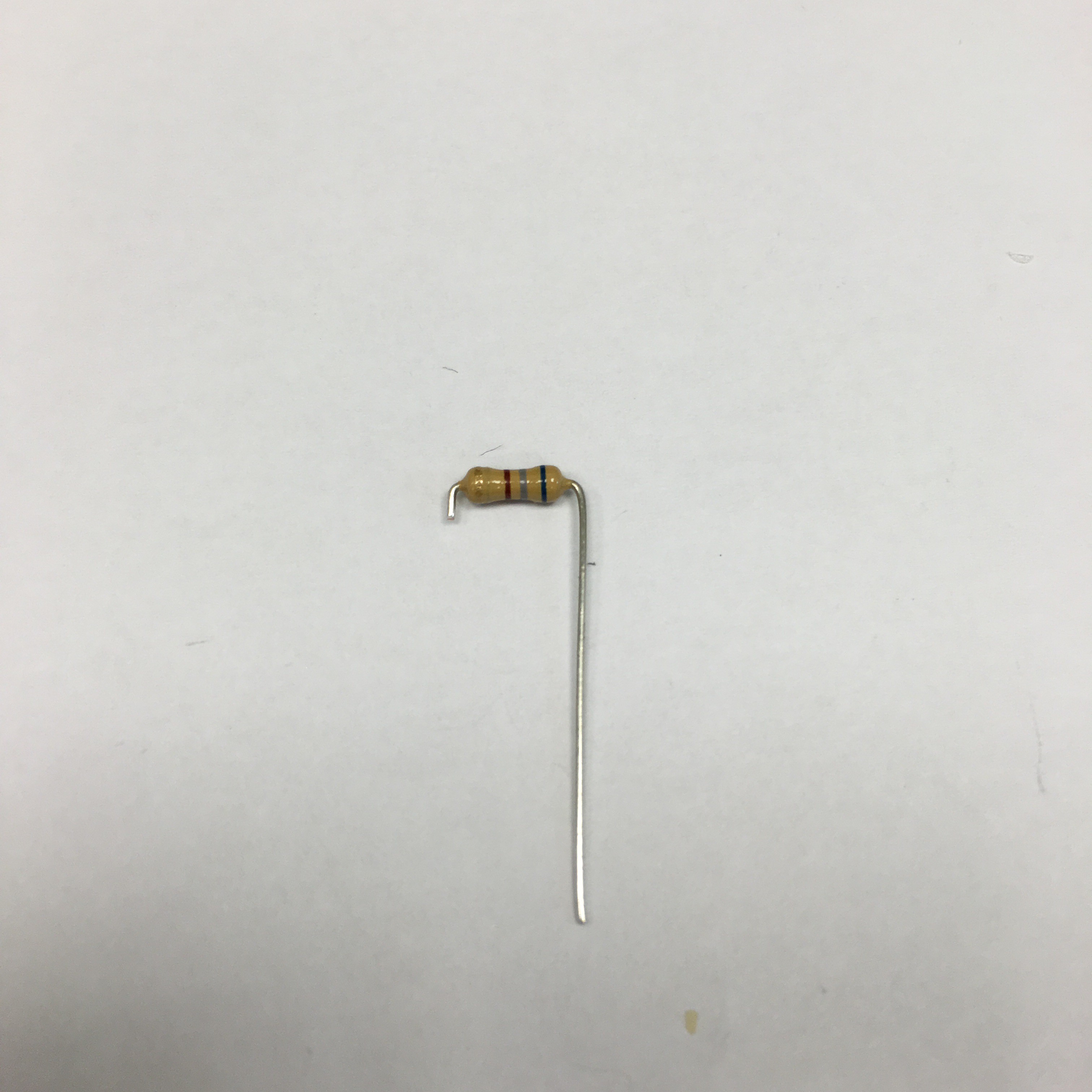
8Step 8
Now we prepare the resistors that is going to connecting to base pin of the transistors. Bend the resistors and cut one side short.
![]()
-
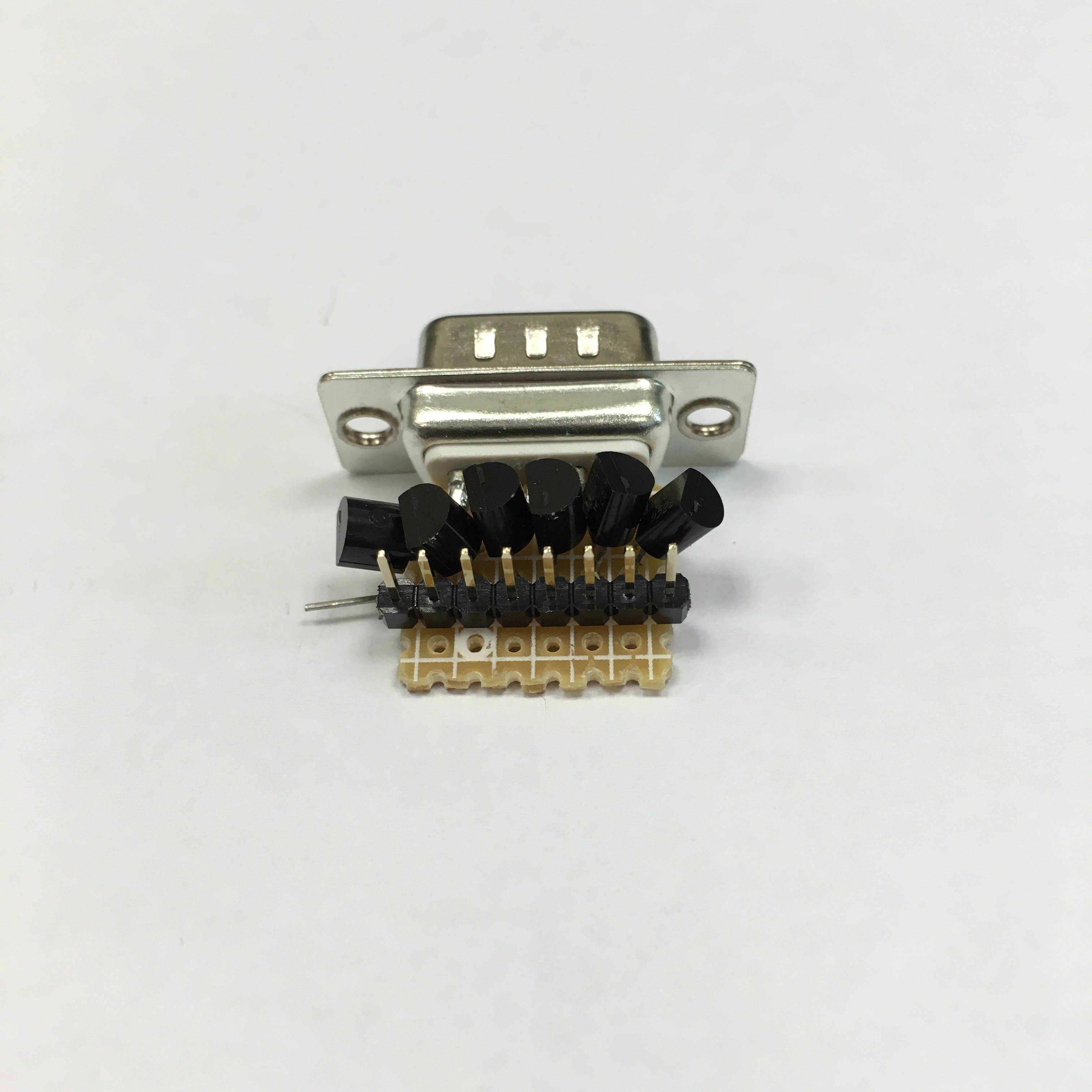
9Step 9
Install a 8-pin pin header to the perfboard.
![]()
-
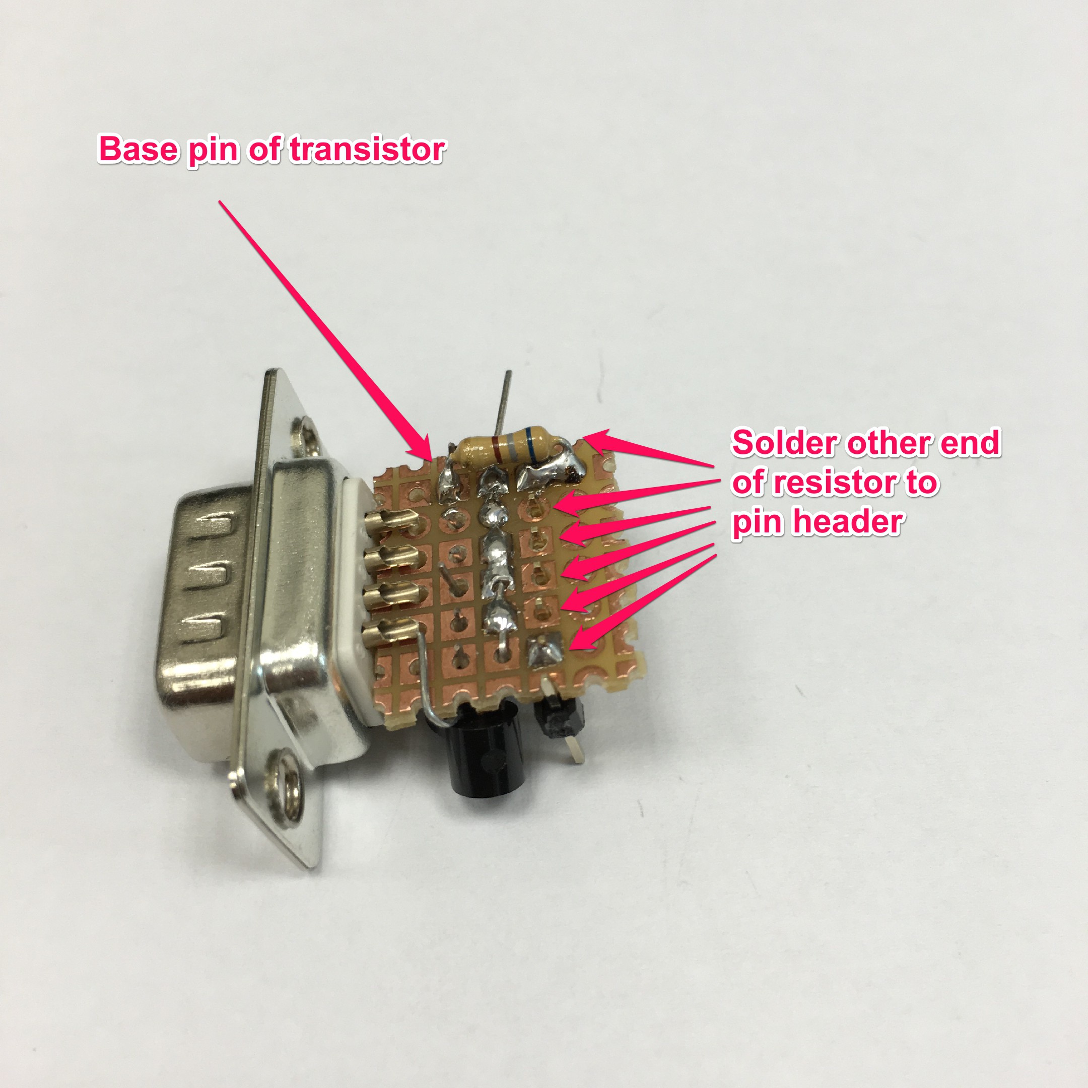
10Step 10
Install the resistors to the copper side of perfboard (4 pins side of the DB-9 connector). Solder the 8 pin header to perfboard.
We now solder the resistors to the 6 pins in the middle of the pin header. Leave the 2 pins on both ends of the pin header alone.
Insert each resistor to perfboard across the pin header and the emitter pins of the transistors.
Then solder one resistor each time, with one end on solder to base pin of the transistor and the other end solder with the header pin. Cut extra part of the pin after soldering the resistor to the header pin.
![]()
Lightsaber Stand for Hackers
Making a Star Wars themed lightsaber scoreboard for 2015 HITCON CTF
Discussions
Become a Hackaday.io Member
Create an account to leave a comment. Already have an account? Log In.