Close
0%
0%

RGB WIFI Dimmer

12V Dimmer with 4-PWM Outputs a 3A and ESP-01 suitable pinheader
Similar projects worth following
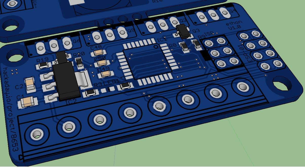
After I designed a small dimmer with an ATmega8, I thought it would by nice to trigger the brightness of the connected LEDs with my smartphone. So I started this project. The Dimmer uses all three PWM Channels of an ATmega8 and timer 0. Also there is a Pinheader to onnect an ESP-01 modul to the board, for the communication betwenn the ESP to the dimmer module I will use UART.

This dimmer is designed for 12V led strips (anode common). The max output current of each color channal is 3A and the max current of the white channal is about 5A all limited by the size of the pathways of the pcb. The voltage limit is caused by the ldo.

  • 1 × ATmega8 Microprocessors, Microcontrollers, DSPs / ARM, RISC-Based Microcontrollers
  • 1 × ESP-01 Wlan modul
  • 4 × IRF3205 Discrete Semiconductors / Power Transistors and MOSFETs
  • 4 × 2N7002 Discrete Semiconductors / Transistors, MOSFETs, FETs, IGBTs
  • 1 × AMS1117-3.3 Power Management ICs / Linear Voltage Regulators and LDOs

View all 8 components

  • Local Website

    Ethon03/04/2016 at 16:21 0 comments

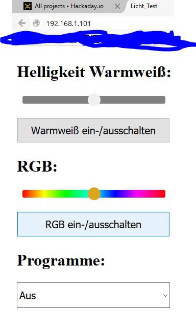
    To control the LEDs I created a small HTML site with some buttons, range and select options. At the moment it sends the informations to the server (ESP8266) where they will by interpreted and converted to UART for the ATmega8.

  • Hardware ready

    Ethon01/22/2016 at 10:57 0 comments

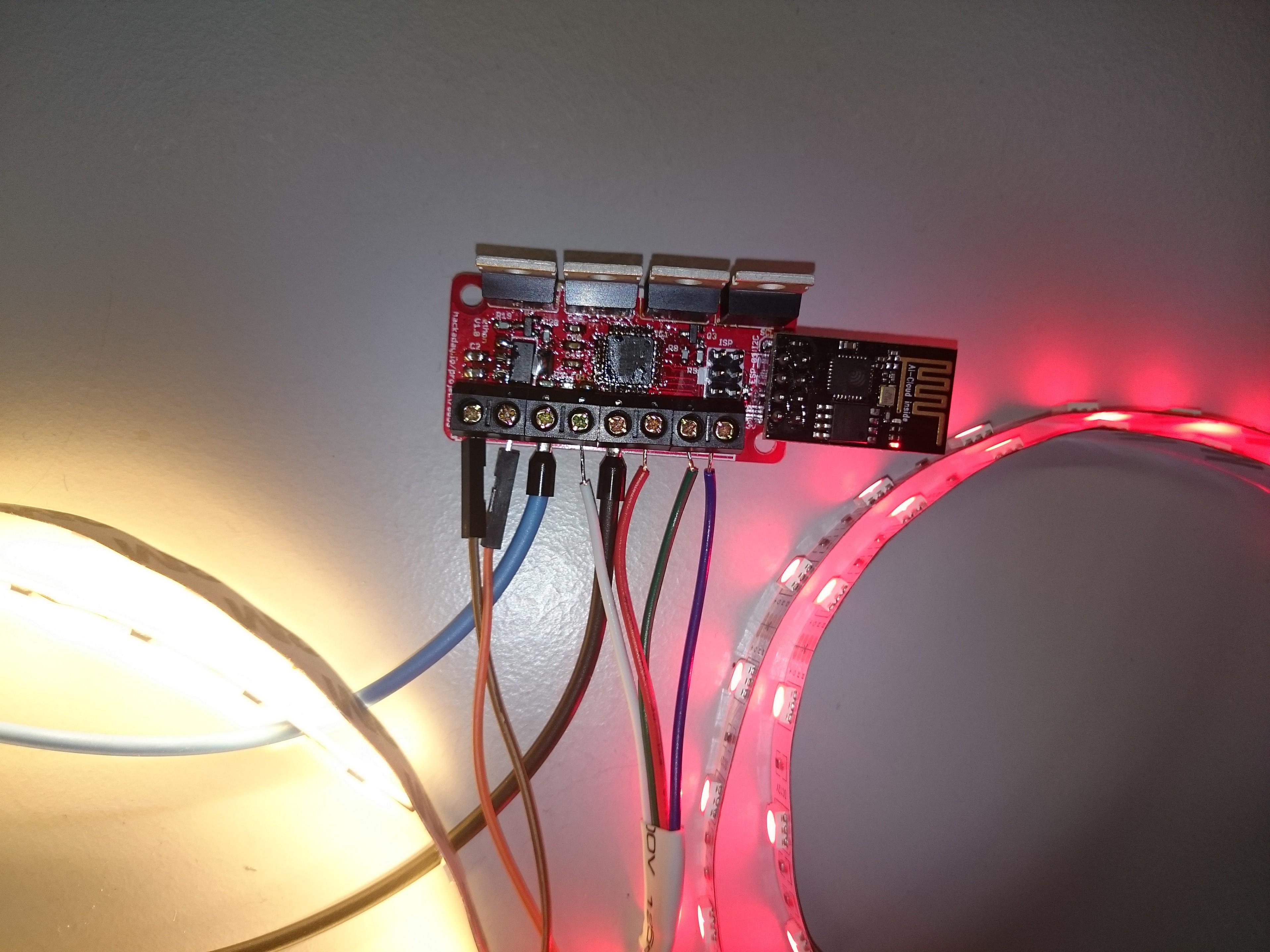
    After a while of trieng I finished the hardware, one problem was to get the best values for the gate resistors, another problem was that I forgot to add a +3V3 connection to CH_PD of the ESP01 header. As you can see on the picture all is working fine. The voltage drop over the N-FETs is below 0.02V.

    Here some facts:

    power input : ESP01 + PCB = 90mA * 12V = 1,08 (HelloServer.ino)

    power input : PCB = 20mA * 12V = 24mW

    warm white leds 5660 600 = 850mA * 12V = 10,2W/m, voltage drop 0,5V after 1m

    RGB leds 5050 = 1,1A * 12V = 13,2W/m, voltage drop 0,5V after 1m, all three colors on max

  • Testing PWM with LED strips and N-FET construction

    Ethon12/16/2015 at 09:42 0 comments

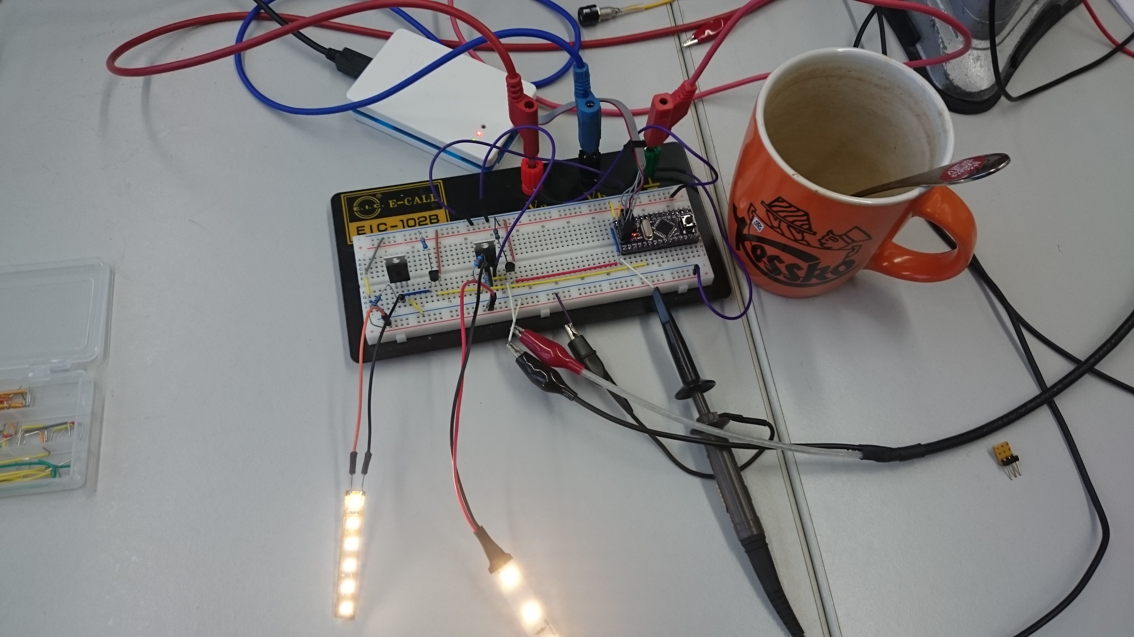
    Today I tested the N-FET construction with small pieces of LED strips. With all four PWM channels, all of them have around 500Hz an can have any duty cycle. The main result of this test is, that I have to choose other values for the pull-up resistors. I choose 3k3 for 3V and 4k7 for 12V.

    For the tests i used a breakboard from al1. https://hackaday.io/project/6768-atmega8-breakout

  • Some programming

    Ethon12/10/2015 at 13:15 0 comments

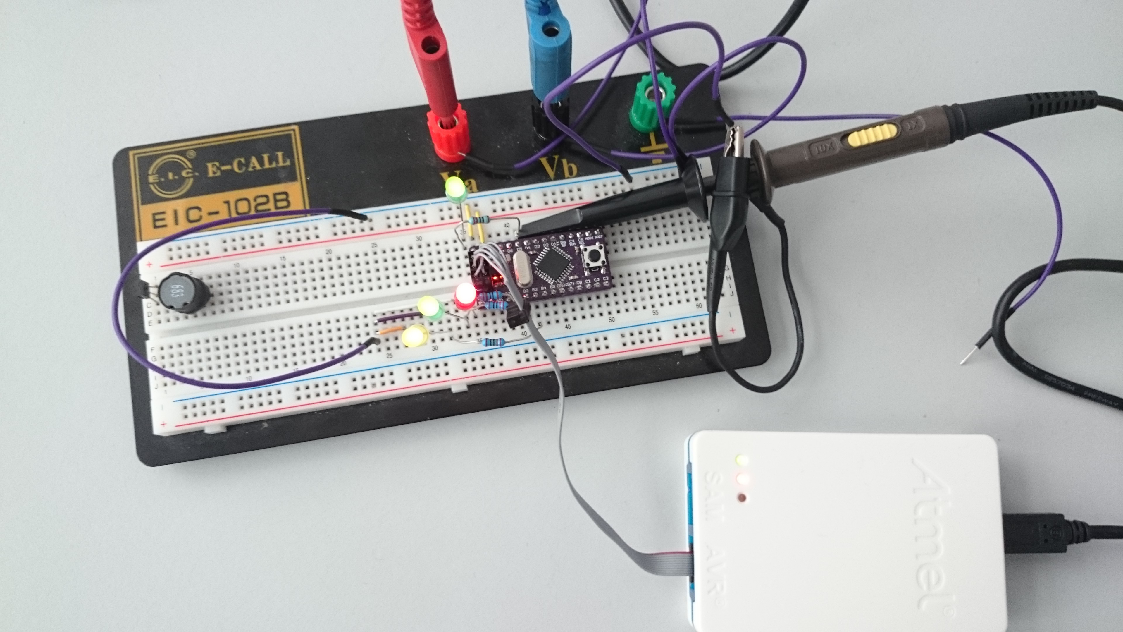
    Today I wrote some lines codes for the project and checked the results with an oscilloscope. I created 4 PWM signals, three with the Output Compare Registers of the µC and another one with timer0 by using an ISR. The slowest PWM has 600Hz and the other three have about 30kHz frequency which I want to use for the RGB LEDs.

    void ATmega8_PWM_8bit_Software_timer0(uint8_t value)
    {
    	softpwmvalue=value;
    }
    
    void ATmega8_PWM_8bit_Software_timer0_setup(void)
    {
    	DDRD	|=(1<<PORTD5);		//set D5 as output
    	TIMSK	|=(1<<TOIE0);		//Counter0 Overflow Interrupt Enable
    	TCCR0	|=(1<<CS00);		//set prescaler to 1
    }
    ISR(TIMER0_OVF_vect)
    {
    	static uint8_t counter;
    	counter=counter+1;
    	if (counter>softpwmvalue)
    	{
    		PORTD &= ~(1<<PORTD5);			//off
    	}
    	else
    	{
    		PORTD |= (1<<PORTD5);			//on
    	}
    	
    }

  • New PCB desing

    Ethon12/07/2015 at 20:45 0 comments

View all 5 project logs

Enjoy this project?

Share

Discussions

Similar Projects

Does this project spark your interest?

Become a member to follow this project and never miss any updates