Close
0%
0%

RPi WiFi

Fast RPi WiFi without USB

Similar projects worth following
WiFi on a Raspberry Pi using the HAT connector and an ESP8266. The goal of this project is to add WiFi to the Raspberry Pi Zero while keeping the USB port free for devices or OTG connection to another host.

The instructions below tell how to connect a $2 ESP-12F module to any Pi that takes HATs with a small amount of soldering, and how to get it working under Raspbian. There are KiCad projects in the sidebar for inspiration and a starting point for ESP8266 SDIO projects.

When the Raspberry Pi Zero was announced, a significant chunk of the hacker world dismissed it for having the same fatal flaw as the other Pis: only one USB host port for high speed I/O.

Network connectivity is a major reason that people base projects around a Pi or other embedded Linux board. The 2B and B+ both have onboard USB hubs providing 4 USB ports and an Ethernet interface, making it easy to connect to a wired network or add on a USB WiFi adapter. But the A+ and Zero do not have this luxury. You need an external hub to get the same functionality, which compromises the size advantage and makes for an unwieldy cable mess.

That's unfortunate, because other embedded Linux boards in similar form factors are at least $50 (Intel Edison). These often are designed for commercial products, and so have hacker-unfriendly interconnects that need a breakout board that drives the cost up even further. What's worse is that alternatives don't have the same online support community that Raspberry Pi has fostered.

What the Zero desperately needs is WiFi that doesn't involve the USB port.

SDIO and HATs

The BCM283x SoCs at the heart of every Pi has two MMC controllers. One of these connects to the SD card slot that the Pi boots and runs its OS from. The other has largely been ignored, but comes out on the HAT connector as alternate functions on GPIOs 22-27. Recent kernel and boot blob changes have enabled these pins to be mapped to the MMC controller that also supports SDIO devices.

SDIO started out as an extension of the SD spec to allow for cards that have functionality beyond flash storage. Some PDAs could be expanded to have WiFi or cameras through SDIO. Although smartphones killed the market for SDIO cards by integrating these common features, the bus still lives on as a bridge between SoCs and WiFi modules.

At the time of this writing, the rpi-4.2.y branch of the Raspberry Pi supports the SDIO interface on the HAT connector well. Simply build and install the kernel and edit /boot/config.txt to include the following line:

dtoverlay=sdio,poll_once=false

This enables SDIO on the HAT connector, and asks it to poll for SDIO cards past the initial driver probe at boot time (more on this later).

Enter the Eagle

In all the excitement over the Zero, I noticed a bunch of questions about using cheap ESP8266 modules as a WiFi bridge. Usually these threads were killed by someone by saying that the SPI interface would constrain the speed too much. Fortunately those questions jogged my memory a bit.

I remembered this blog post showing a decapped ESP8266, noting that in the corner is printed "ESP8089". The post mentioned that ESP8089 is another Espressif part, a commodity SPI and SDIO to WiFi chip. That got me thinking that, if the ESP8089 and ESP8266 are the same die, then there is a good chance that an ESP8266 module could work as an SDIO WiFi adapter on the Pi.

Espressif isn't helpful with ESP8089 documentation, but some Googling landed me at the center of the cheap Chinese tablet universe. That pointed me to a driver in a kernel tree for a specific Rockchip-based tablet that happens to have an ESP8089 adapter, as well as an attempt to break out an older version of the driver as a standalone module to use with ESP8089 in SPI mode.

So there's a driver, and possibly a physical interface between the Pi and ESP8266, but what about firmware?

The ESP8266 we're all familiar with normally boots from an off-chip SPI flash device, and can optionally boot code over the UART. The determination of how to boot (UART vs SPI) is done by GPIO strapping at power-on. Most ESP modules are set so that one pin alternates between booting from SPI flash or the UART. This lets the UART be used to download new firmware to the SPI flash when hooked to a PC and to run from flash when not. But the sparse ESP8266 documentation does mention a third SDIO boot mode, but there is no explanation of how to use it.

It turns out that SDIO boot is intended for the ESP8089. The driver contains a few firmware...

Read more »

esp-12f_hookup.svg

Hookup diagram for the ESP-12F

svg+xml - 64.02 kB - 02/23/2016 at 20:35

Preview

  • 1 × ESP-12F WiFi module - ESP-12E will probably work
  • 1 × Raspberry Pi Any HAT compatible Pi: A+, B+, 2B, Zero
  • 6 × 33 ohm resistor
  • 1 × thing to stick the ESP-12F on perfboard, cardboard, a graham cracker, Pi Zero, etc.
  • 1 × 2x20 HAT Connector (optional) run of the mill dual row 100 mil 40 pin female header. or just solder to the Pi Zero

  • Under construction

    ajlitt07/09/2024 at 15:33 0 comments

    tl;dr: GitHub driver broken in latest Pi OS, fix coming someday

    Hey. It's been a minute. Or 7 years since the last update.

    In that time we've seen 2 new Pi SoC generations, an update to the Zero SoC, a mountain of ESP32 iterations, and even official device support from Espressif for ESP32 variants. Meanwhile I've been updating the driver to deal with kernel changes to the best of my ability. Usually it's a simple change to keep in sync with an updated kernel API and takes no more than an hour of my time. I even have an old Pi2 for testing and cutting releases of the Debian package at the ready for when one of these charges breaks the driver.

    Usually I find out about these problems with a notification that someone submitted an issue to the edp8089 project on GitHub. Early on I might even get a PR with a fix ready to go. However that hasn't happened in a while, and for the last few years I only find out when I fail to upgrade one of the Pi Zeros with the ESP8266 I still have in use.

    Last weekend I ran into one of those failures, and spent a few hours root causing the issue. However this time it turned out to be three issues. The first issue is a segfault due to an update to the function table for mac80211. This was an easy fix.

    The other two are hairy. The kernel API for GPIO control the driver uses to reset the ESP to run the loaded firmware has been removed. The current API, gpiod, will require that we use a devicetree overlay to pass the platform GPIO to the driver. This is the Right Way to handle platform differences, but changes how users will deal with the driver. I'll make sure the Pi .deb installs a corresponding.dtbo, but those using different platforms will have to cook up their own. For now, I have a hack in place using the deprecated-but-not-eliminated libgpio driver that is very Pi specific and very much the Wrong Way. Sorry to all the non-Pi users, you're on your own for a while.

    The third issue is that DKMS no longer supports making Debian packages. I'll have to create my own package config, which is not trivial, but certainly someone else has a good example I can start from.

    Please be patient. I still plan to support this project for as long as I can. If you're starting a new project, consider using the Espressif ESP32 driver and an ESP32-C3 instead as I trust them to do a better job maintaining the driver than me, and the newer chips will have a longer product lifespan than the ESP8266.

  • WiFi broken? Update your driver!

    ajlitt05/11/2017 at 02:58 1 comment

    Recently Raspbian switched to a 4.9 kernel from the 4.4 based kernel that's been the norm for a while. This breaks the esp8089 driver. If your esp8089 module no longer loads following an apt-get upgrade, this is likely the problem.

    Thankfully den4ix on github issued a pull request this morning that updates the APIs for 4.9. The fix is in the latest Debian DKMS package released this afternoon.

    To update the driver, download the new esp8089 DKMS package from github and install on top of the old package:

    wget https://github.com/al177/esp8089/releases/download/1.9.20170510/esp8089-dkms_1.9.20170510_all.deb
    sudo dpkg -i esp8089-dkms_1.9.20170510_all.deb

    Reboot after the package is installed to reload the esp8089 driver.

  • It's been fun

    ajlitt02/28/2017 at 15:27 3 comments

    Now that the Raspberry Pi Zero W is out, there's not much reason to use a WiFi Pants board. The Zero W is more compact, cheaper, and has out-of-the-box Raspbian support for WiFi. Also Bluetooth.

    If you need battery power for your Pi Zero project, please consider the amazing LiFePO4wered/Pi .

    Thanks to everyone who supported this project!

  • Licenses, longevity, lights

    ajlitt10/23/2016 at 04:01 0 comments

    It's been a while, huh?

    Much has happened over the last few weeks. The biggest news is that Espressif has agreed to allow their ESP8089 driver to be licensed under GPLv2 and the associated binary blob firmware to be put under the Apache license. Now the driver powering this project as well as many tablet devices can be submitted for inclusion in the Linux kernel. A few embedded Linux enthusiasts have stepped up to clean up the code and push it through the kernel patch submission process. Thanks to Jeroen@Espressif for getting the approvals, and the free-electrons folks, jwrdegeode, noahwilliamson, and icenowy for their ongoing work in making the driver kernel-ready.

    About two weeks ago I sold the last finished WiFi Pants kit in my inventory. I'm also running out of my long lead time components: PCBs, ESP modules, and the long stack through headers. I will be doing another run of kits which should be in stock in a couple of weeks, but after those are gone it's going to take a couple of months to build any more.

    Finally, I was lucky enough to participate in the first Hackaday TV hangout and talk for a few minutes about my project with Sophie Kravitz and Limor Fried and hear about some really neat Pi hacks. But while excitedly rambling on about my WiFi Pants project, I forgot to point out the demo I put together to show off the WiFi pants board's power supply. You can see it on the bench behind me in the video blinking away.

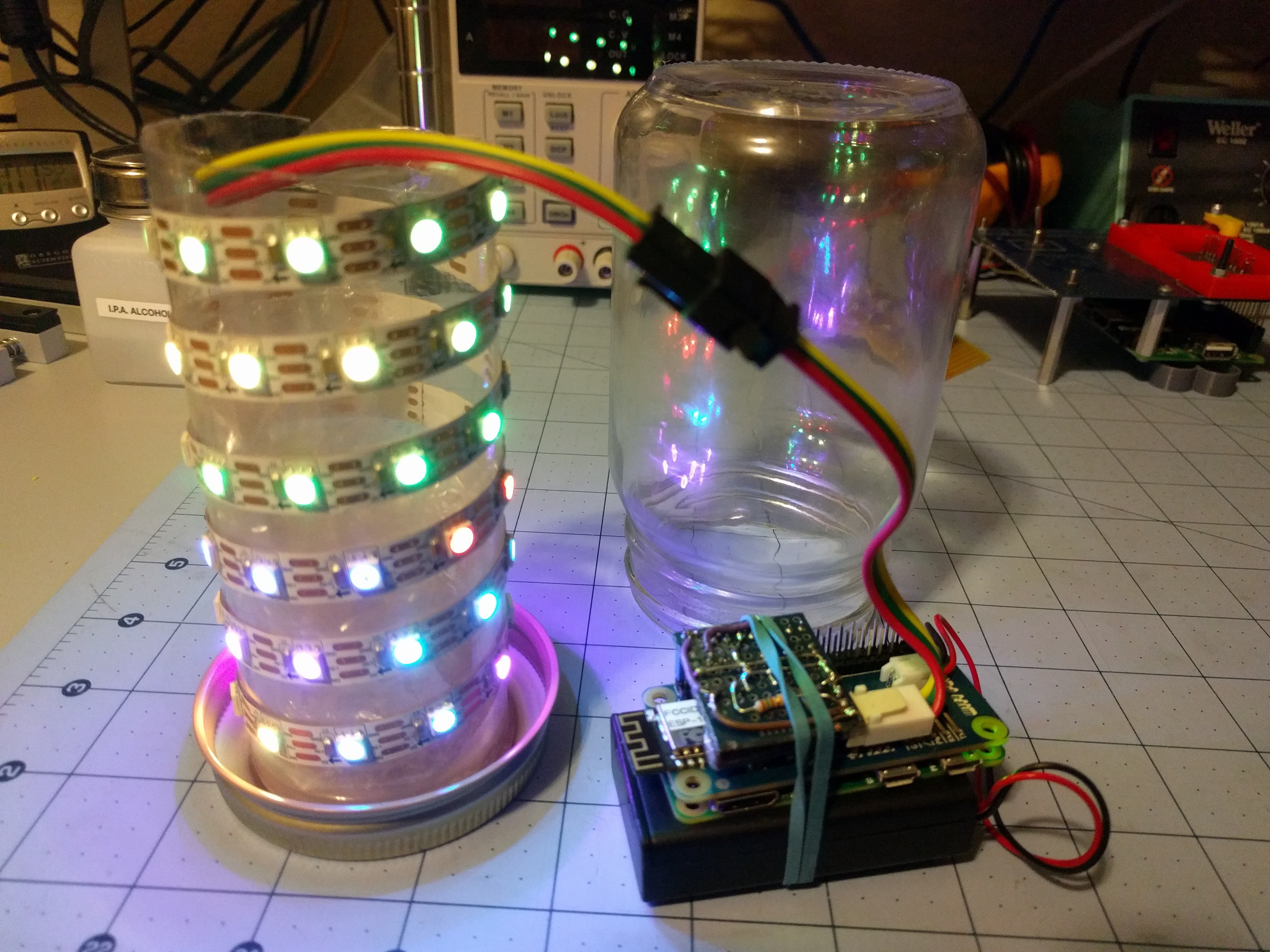
    Behold, the Access Point Sniffer Thing With LEDs in a Jelly Jar That I Haven't Considered Naming Until Right This Moment, or APSTWLJJTHCNURTM for short:

    It's a WS2812 LED strip in a jar that changes patterns depending on the number and strength of WiFi accesss points in the area. It uses a 60 LED WS2812 strip, WiFi Pants, a Pi Zero, 3 AAA NiMh batteries, a jam jar, a plastic tube from the packaging for a USB charger, plenty of clear packing tape, a few dabs of hot glue, and a WS2812 level shifter board made with junk box bits. Software is in Python using the rpi_ws281x library for talking to the LEDs and iw_parse to simplify the AP scan.

    Every second or so the Pi does a scan of the available networks. The networks are sorted by the signal strength and assigned an LED for each 4dB of signal strength. Each access point gets its own color by hashing the last 3 octets (the non-OUI portion) into hue and saturation. You can see at the bottom in the gif above that the LEDs towards the bottom of the jar are more uniformly colored and don't change much, while the APs that have weaker signals dance around with a larger variety of colors towards the top as they come in and out of range.

    Total time spent on this was about 5 hours. I figured that the string at full brightness plus the Pi and ESP8266 would push near the 2A limit of the boost converter, making it a good demo. However the LEDs at full power saturated my webcam to the point that the jar looked like it was filled with burning magnesium, so it's limited to 1/8 brightness. That's probably for the best, as the AAA batteries droop too much at full LED power to keep up with the 4A or so the converter pulls at its limits.

    Thanks HaD, Adafruit, Limor, Sophie, and all the other hackers for a fun hour of sharing projects!

  • Need Pants?

    ajlitt06/07/2016 at 19:34 3 comments

    I have a few WiFi Pants boards listed on Tindie. Have at 'em

  • Driver update

    ajlitt05/23/2016 at 15:52 3 comments

    Last night I checked in a change to the esp8089 driver that automates toggling the reset (CH_PD) on the ESP by GPIO. With this change ESP hacks based on the instructions here will automatically come up during boot without any scripting or external reset circuits. This also issues a reset on module unload which is needed so that the ESP is detected after a soft reboot (reboot on the command line, etc) and keeps the module from OOPSing when reloaded without a previous reset.

    The project instructions have been updated to reflect this change. If you previously added sysfs GPIO or module unload commands in your init scripts for the ESP (rc.local and otherwise) you'll need to take them out. The driver defaults to GPIO0 (ID_SD like the WiFI Pants uses), but you can pass the esp_reset_gpio module parameter with the GPIO number your board uses. This should be platform agnostic as long as the target has a kernel GPIO driver.

    The driver still isn't ideal since it must always be rebuilt every time the Pi kernel changes. On other Debian based systems this could be handled with dkms, but the Pi Foundation's non package based kernel scheme makes it difficult. Of course I have a build process to help with this, but that's dependent on a network connection and gets unpleasant on the Zero. One solution would be to build the driver against each Pi kernel release and index it by the kernel's commit hash (like rpi-source). If anyone has ideas for a cheap (or free) binary release hosting service I'd be open to setting up an automated build server.

    As for the WiFi Pants... I still have the first batch sitting on my desk. I wanted to get this driver change in to simplify initial setup, and still have some documentation to do. Keep an eye on the github wiki and on this project for details.

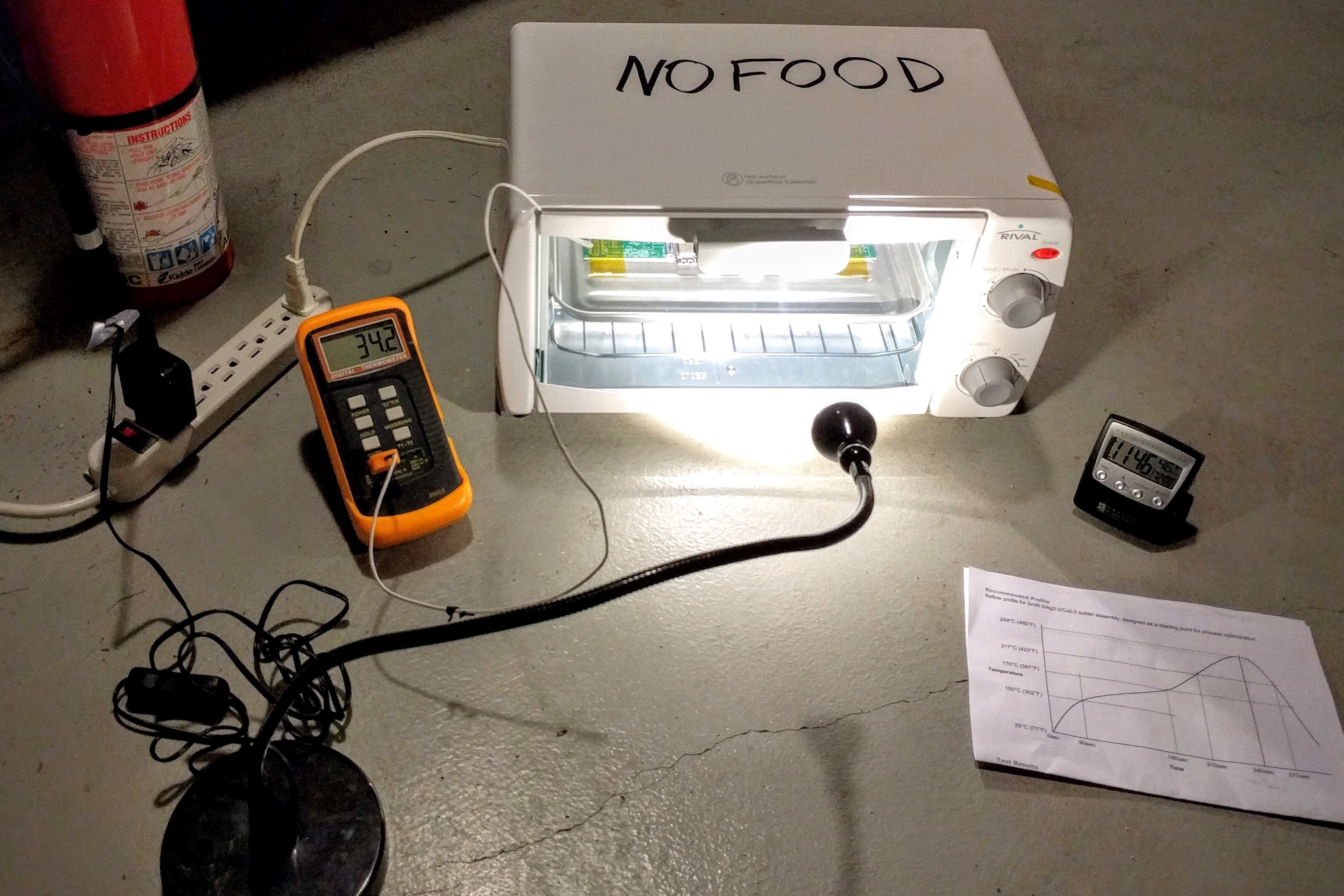
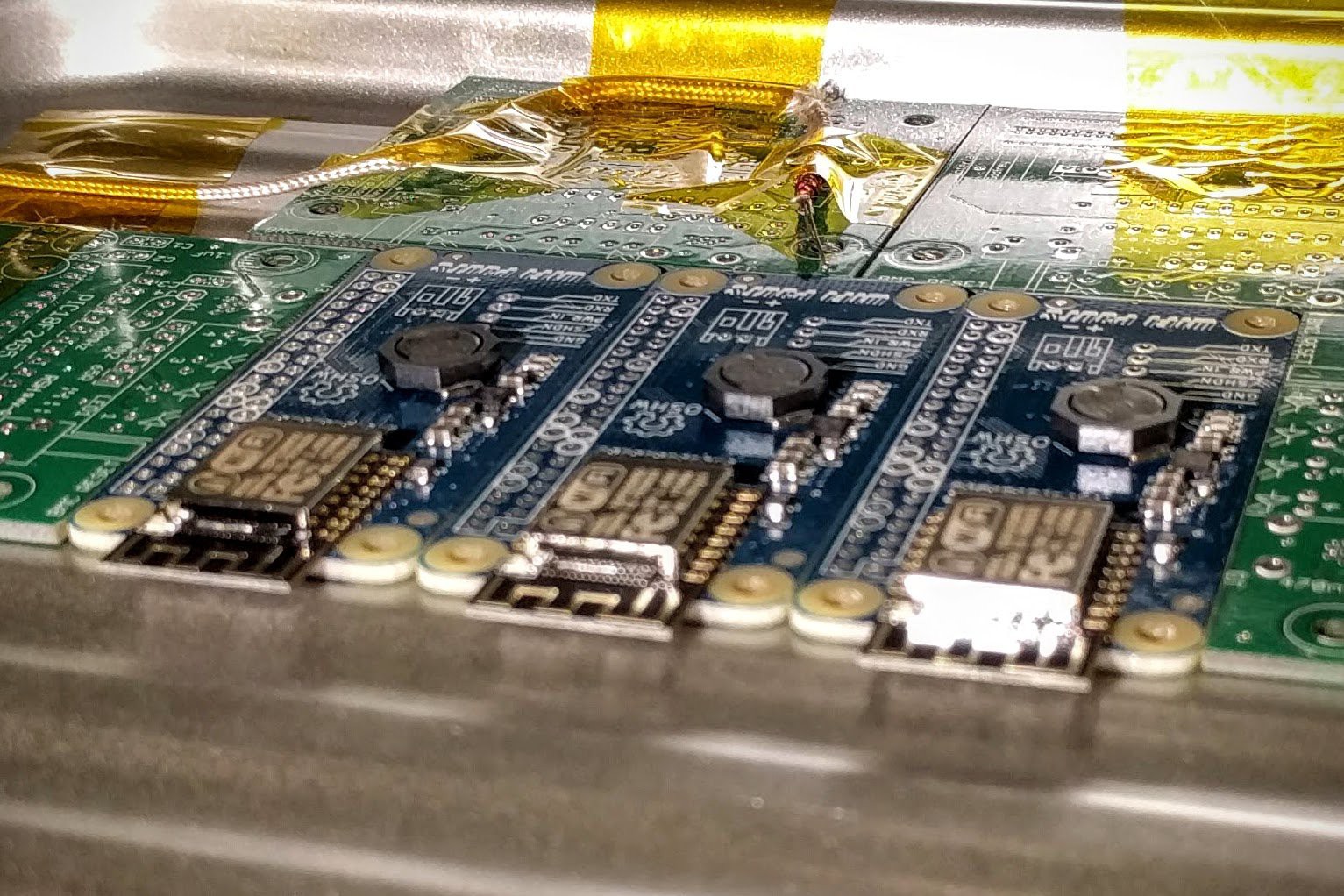
  • Production starts!

    ajlitt04/14/2016 at 06:04 4 comments

    Repeat 9x.

  • Testing the tester

    ajlitt04/10/2016 at 16:59 0 comments

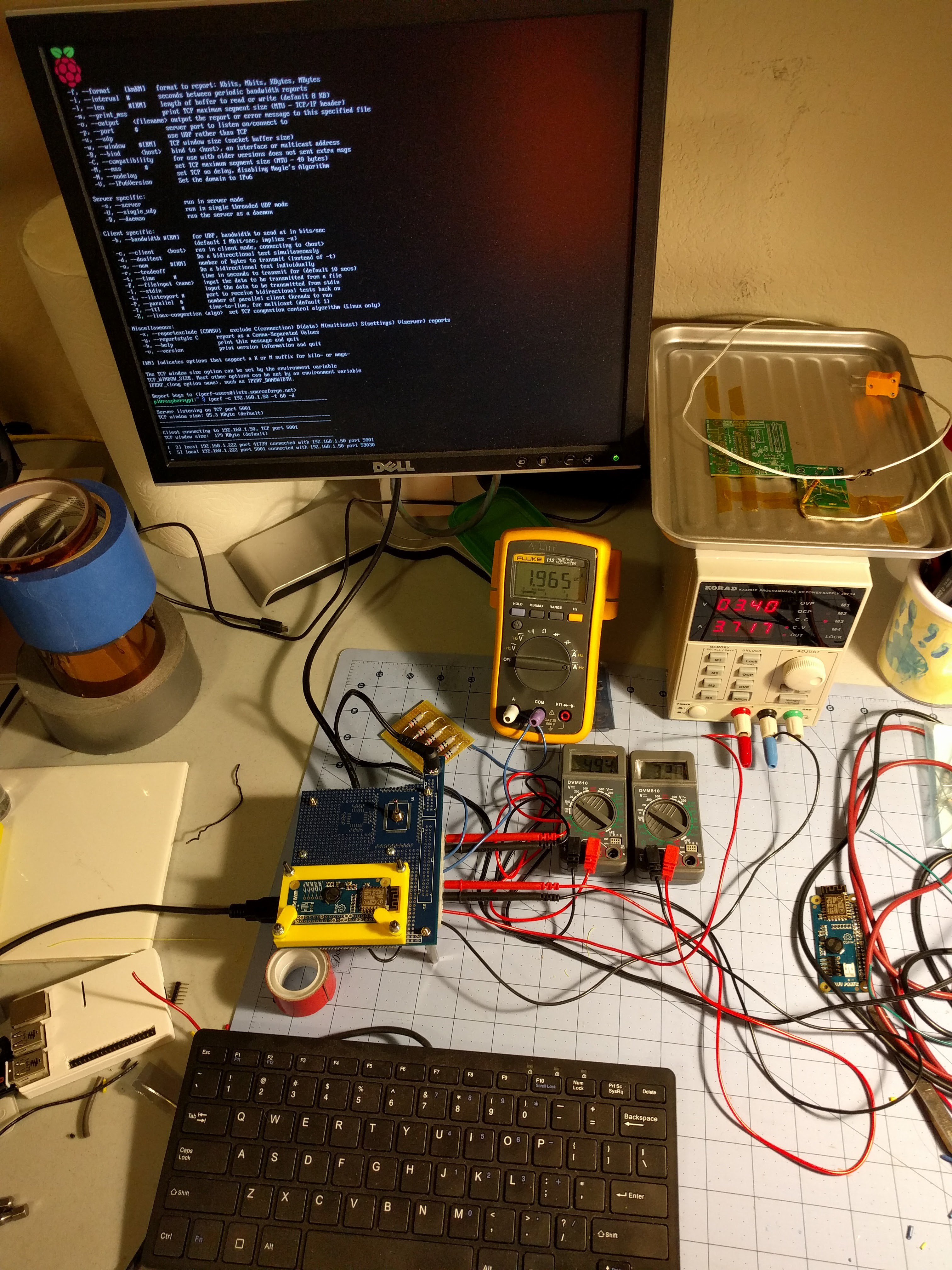
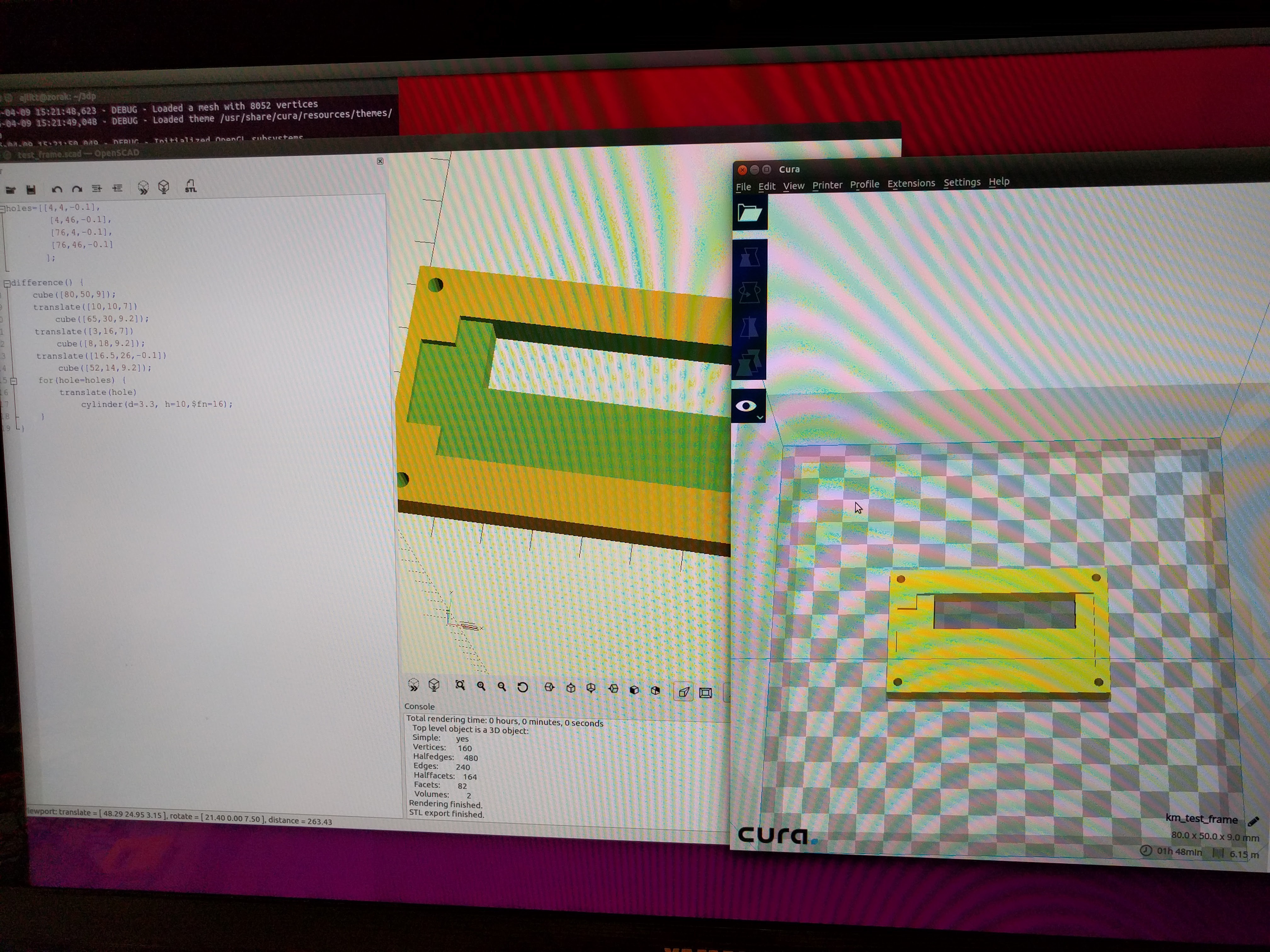
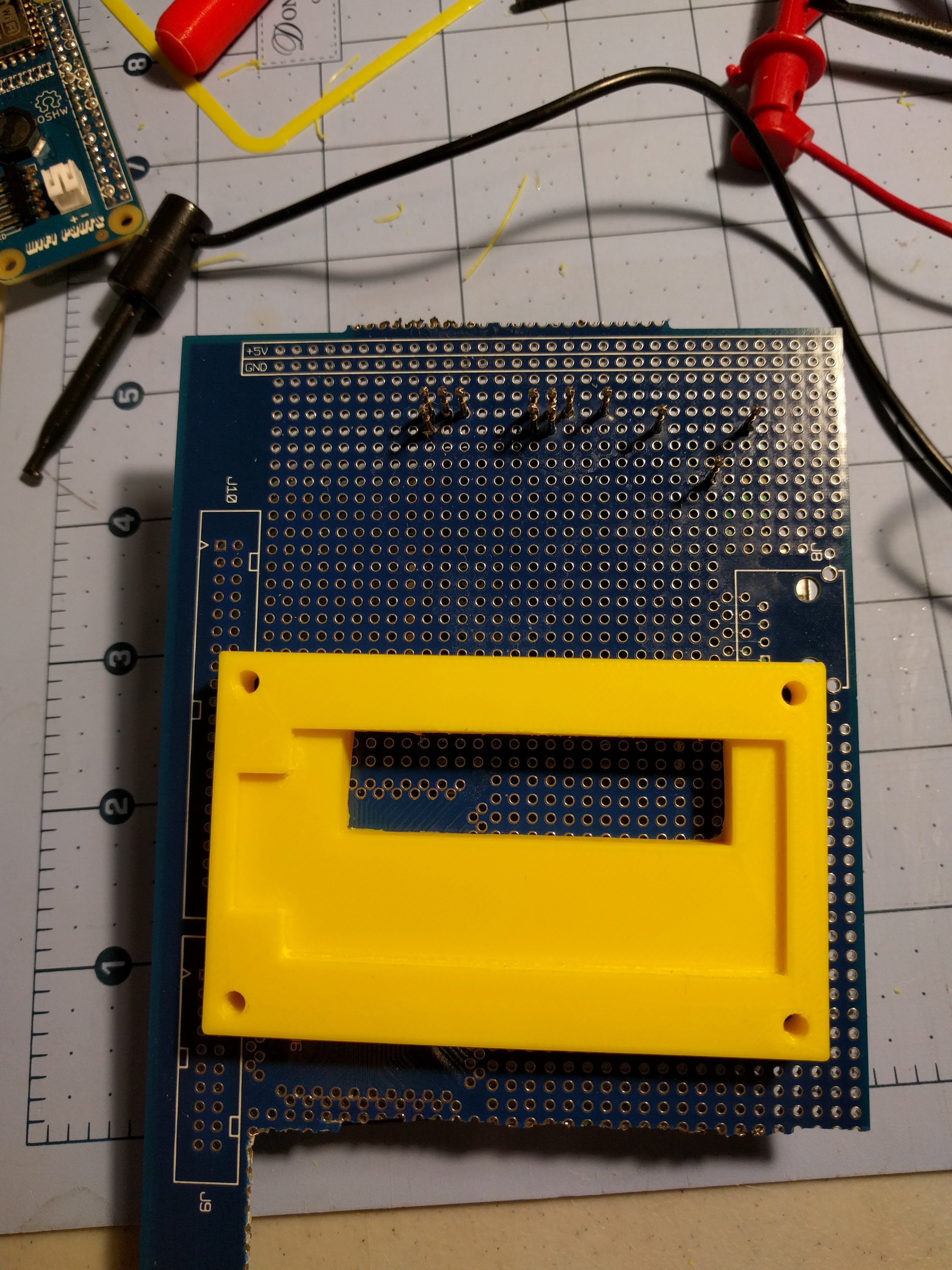
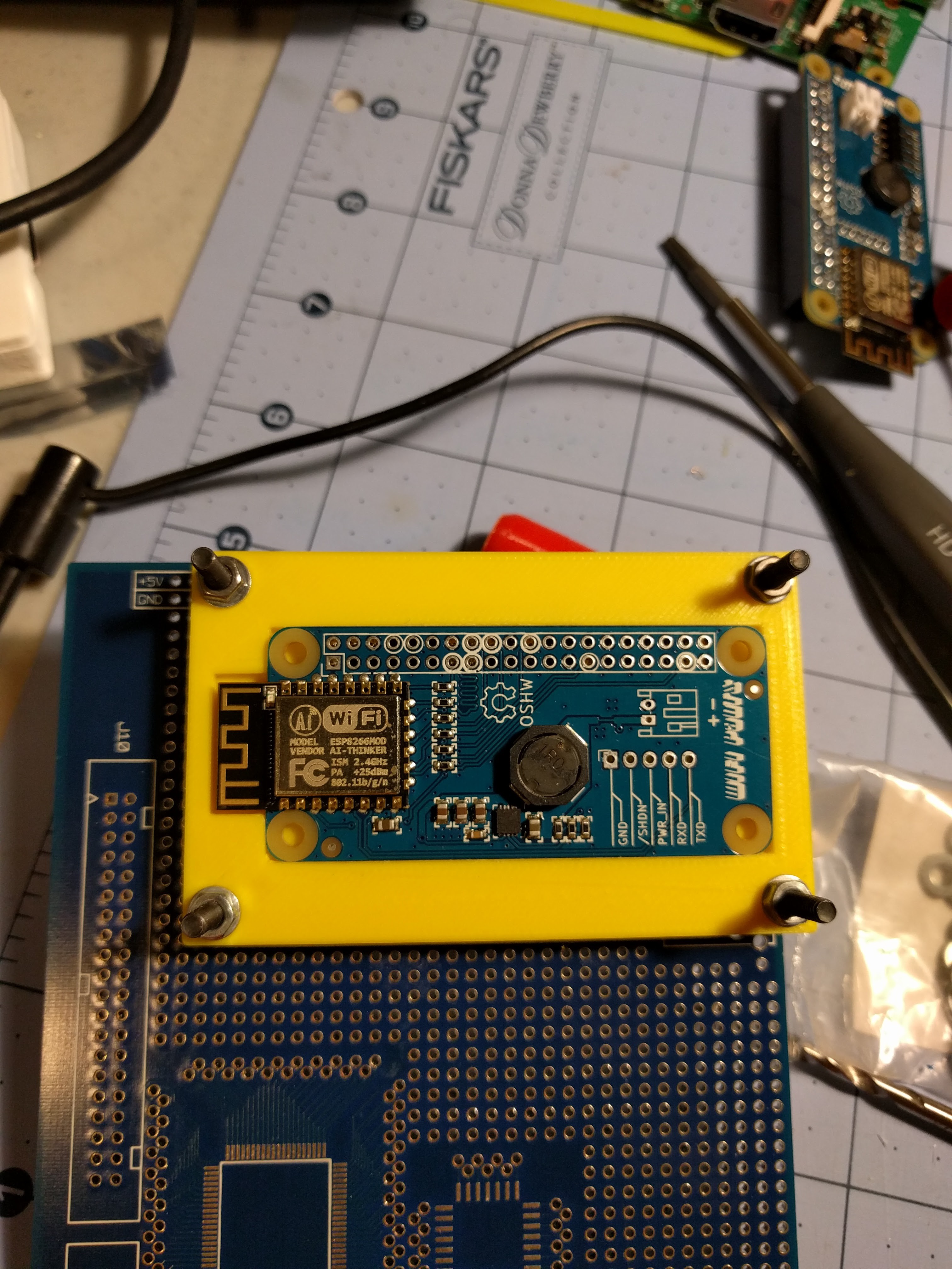
    The test jig / bed of nails is coming along nicely. I OpenSCAD'd a mount and retention clips for the DUT, and with some filing and drilling out the PCB the DUT and pogo pins line up reliably and the DUT stays put. A choco-block terminal strip connects to the PSU and lets me clamp to the disposable DMM probes. The DMMs need test leads with an odd mini banana plug, so rather than trying to make custom cables I just clamp the probes in the terminals. They're used only for voltage measurement so this is fine. Some more drilling, standoffs, and a power jack for separate power to the Pi A+ round out the fixture.

    The output load is simply 8x 20 ohm power resistors in parallel for 0.4 ohms which gives 2A at 5V. They get a little toasty but don't seem to need active cooling.

    A few bugs to fix in the next couple of days:

    I'm seeing much higher voltage at the DUT for the input than at the fixture's DMM, so I'll try doing the Kelvin sense thing and run separate wires from the terminal block to the pogo pins for the input rail. Unfortunately there's only one pogo pin feeding the input to the DUT so I'm likely not going to see the actual voltage unless I redesign the PCB with a dedicated test pad for the input.

    Also, the regulator is getting excessively hot, moreso than when I've tested it on proto builds. Most of the heatsinking is done with vias to the ground flood on the back, and my design for the mounting frame has a solid fill behind the DUT except for where the pogo pins are. I'm currently reprinting this with much more area under the part exposed and a little vent towards one side in attempts to let the switcher cool naturally.

    The resistor load is working as planned, except it's just below the 2A point I want to test due to wire losses. So I might add another resistor in parallel to get closer to 2.25A which should make for sufficient testing margin. Easy enough since I've got a big bag of spares.

    I drilled holes for three standoffs to support the fixture, but realized I located the pogo pins too close to an edge for one of the corners. Need to find a dowel or something to hot glue there.

    I put a toggle switch from my junk bin on the board so I can shut off the Pi between DUTs, but the switch is flaky and cuts power at the slightest touch. It's shorted closed for now, but I'll eventually get a replacement.

    And a final mistake that should have been obvious: I am seeing lower throughput on WiFi than on my proto builds. I don't see this when using the same DUT carefully held on a Pi's header, so it's likely the fancy recycled perfboard I'm using with the ground plane restricting the signal. That's ok as long as I'm seeing consistent behavior between units.

  • Knife sharpening

    ajlitt04/07/2016 at 17:24 0 comments

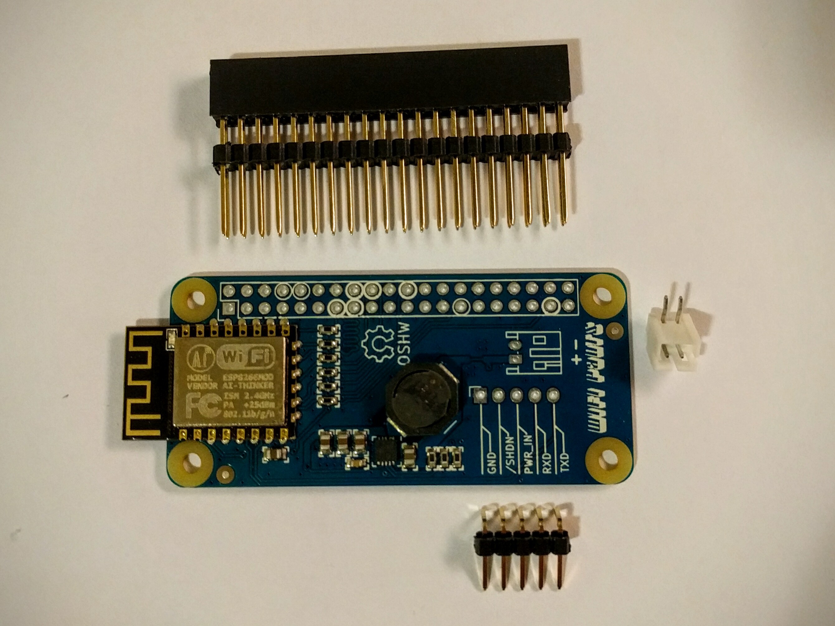
    Now all the parts for my first small run of boards are sitting in a box on my bench, and I've built up a test board. This is what I plan to sell:

    The headers are shipped unsoldered to allow for different assembly options and to simplify packaging. Ignore the plastic spacer on the header, as it can be removed. I'm not in a place to stock a ton of different options, so if you want to mount this underneath a Zero you'll need to find a different header.

    Based on suggestions kindly offered by others, I'll be selling three kits: "full" with everything above, "basic" with only the WiFi populated on the PCB and including all the headers except the JST, and a bare PCB.

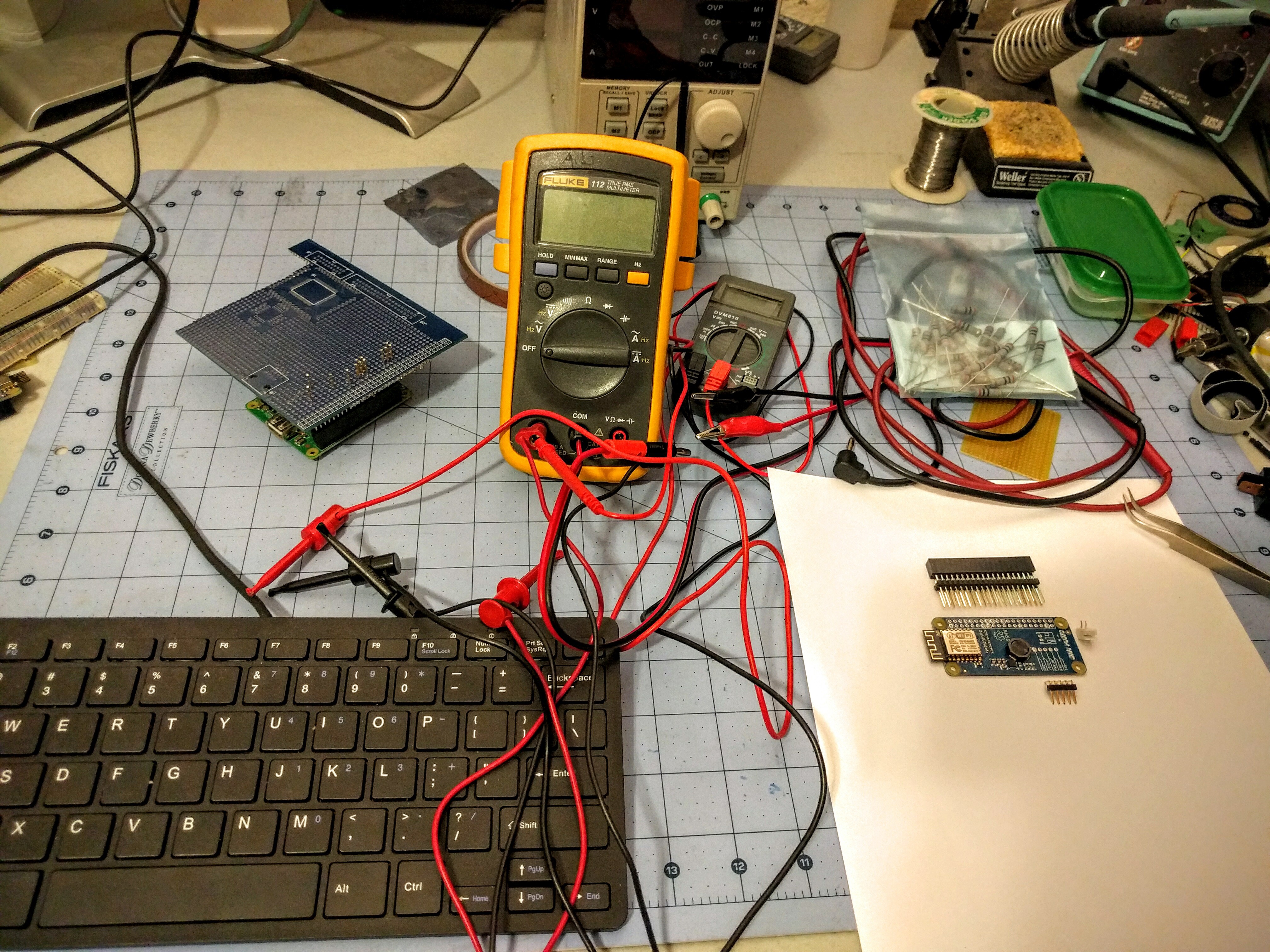
    Although I have materials in hand to crank out boards, I need one critical tool in place before production starts. I want these board kits to work once customers solder them together, so I'm working on a test jig for running the SDIO interface and power supply through their paces. After many years of getting along without a real bench supply, I invested in a nice Korad 30V 5A programmable linear that I can use with a pile of power resistors to run the 5V output to 2A at various input voltages, and to test the undervoltage lock-out. I also got a couple of cheap-o DMMs from Fry's over the weekend for a rough output voltage check, and some miscellaneous bits and pieces to put it together. I intend customers to use this board to run motors, LEDs, and other current sucking peripherals, so I want each board tested at load.

    Eventually I'll have a printed frame for the PCB and stand to take the load off the Pi underneath. I plan to have this working this weekend, and to start cranking out boards.

    I can't give any estimates when this will go on sale. March was exceptionally busy, and I've had little free time to work on this, and April is shaping up to be more of the same. But I'm making progress which I'll continue to share here.

    In the meantime, enjoy this picture of my messy bench:

  • Surprise boards

    ajlitt03/26/2016 at 21:26 4 comments

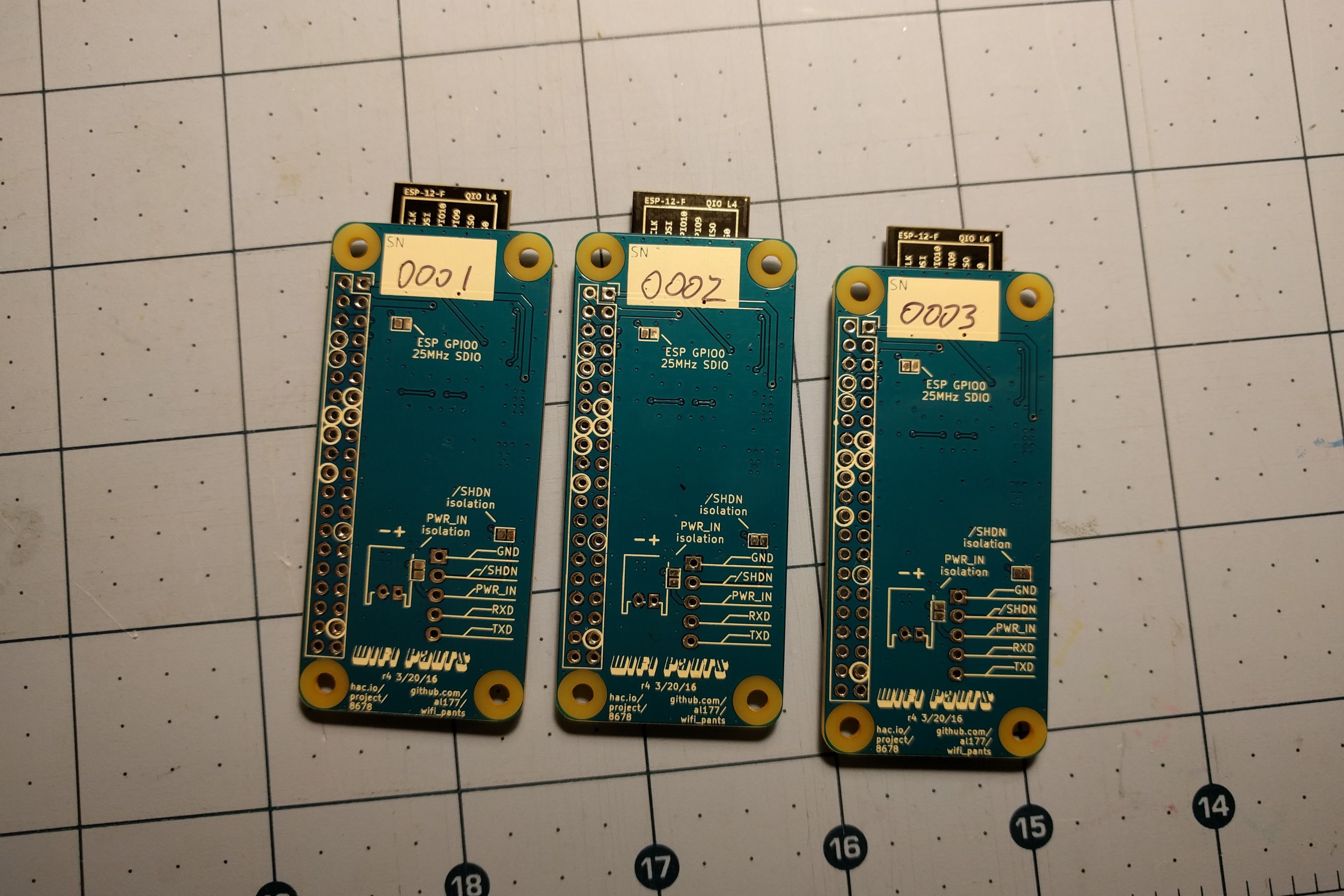
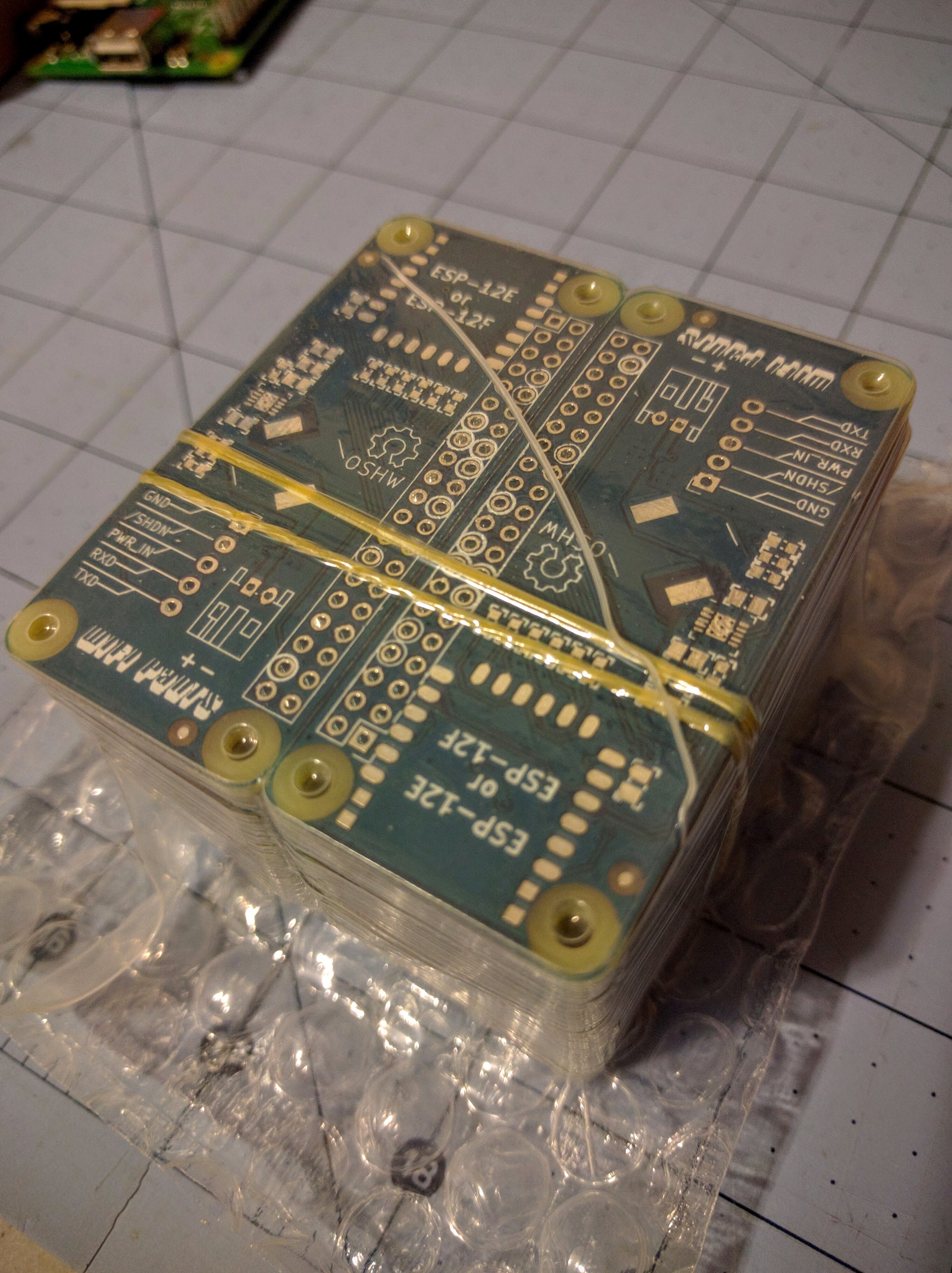
    Up until now I've been ordering OSHPark quick turn proto boards because they're cheap for very low volume. For the initial Pants run I went with Elecrow in China from the good reviews I've heard. I put in the order last week for 50 Pants boards with 3 day shipping to the US.

    DHL just notified me that I should expect them on Tuesday. But I'm totally unprepared. I don't have stencils, I'm missing some of the more expensive parts, I don't have a Tindie account set up yet, I haven't figured out shipping or packaging, I don't have a test jig built yet, and my bench is a mess! I don't know why, but I didn't expect 50 PCBs to be manufactured, shipped halfway across the world, and delivered in under 10 days!

    update - and here they are:

View all 31 project logs

  • 1
    Step 1

    HARDWARE

    (WiFi Pants owners skip to SOFTWARE below)

    You'll need 6x 33 ohm resistors (either through-hole or SMT), some wire, and an ESP-12F module.

    Some variants of the ESP-12E should work as well, but there are some that do not have the GPIO9 and GPIO10 pins connected to the edge, and others that have a different pinout than listed here. From what I can tell there is only one variant of the ESP-12F (labeled "ESP-12-F QIO L4" on the back) so that is a safer bet. ESP-12F also has an onboard 10uF capacitor across the input supply, which saves you from having to add one yourself.

    You probably want something to mount the ESP-12F on. Perfboard is fine, as would be cardboard or just double-sided foam tape on the back of the Pi. No matter what you use, make sure that nothing is under the antenna or range will be greatly reduced. The ESP-12F LED is a good mark for the start of this keepout region.

    I use outdoor double-sided foam tape on my hand-built boards since it's tough but not hard to reposition, and raises the module enough to not short against the board. Creative application of hot glue or epoxy putty might work fine as well.

  • 2
    Step 2

    Make the connections between the ESP-12F or -12E and the Raspberry Pi HAT. Keep wires short as possible, and minimize the number of times they cross over each other. If you're using magnet wire or Kynar (standard issue blue wire) you might want to use a heavier gauge for the 3.3V and GND. Ideally the wire lengths of the 6 SDIO signals should be identical, but even a couple of inches of difference shouldn't matter. If you can, keep SD_CLK close to the average length of the other wires.

    The SDIO signals (names beginning "SD_") should have 33 ohm resistors in series (in between the Pi and ESP-12F connections). It may work with other slightly larger values, or with no resistor at all.

    If using 1-bit SDIO instead of 4-bit, omit D2 and D3. There's not much of a good reason for this though.

    A capacitor of 10uF or more may be needed between 3.3V and GND near the module, though a legit ESP-12F already has a 10uF supply cap onboard.

    Wire it like this:

    SDIO signalRPi HATESP-12F pin / signal
    ESP-03 pin / signal
    CLK15 / GPIO2214 / SCLKFlash pin 6 (CLK)
    CMD16 / GPIO239 / CS0Flash pin 1 (/CS)
    D018 / GPIO2410 / MISOFlash pin 2 (DO)
    D122 / GPIO2513 / MOSIFlash pin 5 (DI)
    D2 (optional for 1-bit)37 / GPIO2611 / GPIO9Flash pin 7 (HOLD)
    D3 (optional for 1-bit)13 / GPIO2712 / GPIO10
    Flash pin 3 (WP)
    -1 or 17 / 3.3V8 / VCCModule 1 / VCC
    -2, 4, 14, or 20 / GND15 / GNDModule 8 / GND
    -27 / ID_SD3 / CH_PDModule 13 / CH_PD

    Note that the CH_PD signal is connected to the ID_SD signal. This must be mapped as a GPIO (GPIO0) and switched to an output and driven low then switched to an input again before the driver is loaded in order to reset the module. This will be added in the near future in the driver.

    The ESP-03 column above is for people who want to use an ESP-03 module instead. This requires soldering to the pins of the SPI flash chip for some of the signals. The SPI flash may be desoldered first, or left in place.

  • 3
    Step 3

    SOFTWARE

    Start with a fresh 32-bit Raspberry Pi OS SD image of 2023-05-03 or later.

    A network connection to the Pi is required for the initial installation for the OS to fetch dependencies to build the driver module. This could be the onboard Ethernet of a model B Pi, a supported USB-Ethernet or USB-WiFi adapter, or the Pi Zero connected through another PC over USB.

View all 11 instructions

Enjoy this project?

Share

Discussions

Rob MacKinnon wrote 12/09/2015 at 22:58 point

Think you could post a circuit diagram?

  Are you sure? yes | no

jonsmirl wrote 12/09/2015 at 21:00 point

ESP_USE_SDIO and ESP_USE_SPI: This macro is used to indicate the SDIO/SPI interface. Only one of the two macros must be opened in esp_config.mk.

  Are you sure? yes | no

jonsmirl wrote 12/09/2015 at 20:59 point

The ESP8089 works both in SDIO and SPI modes as a peripheral chip.  You need version 1.1 or later of the Linux driver code for SPI support.  SPI mode will be slower, but you don't have to remove the flash chip on the module.

  Are you sure? yes | no

ajlitt wrote 12/09/2015 at 22:26 point

At one point I came across reference schematics for the ESP8089 in SPI and SDIO modes, and the SPI example used SD_CLK/SD_CMD/SD_D[0,1].  Unfortunately that means the ESP8089 SPI mode firmware would still require removal of the SPI flash chip.

  Are you sure? yes | no

jonsmirl wrote 12/09/2015 at 23:09 point

I must have been wrong that SPI was on separate pins, I did not look at it closely.

Bare ESP8089 chips run $0.80-$0.90.

  Are you sure? yes | no

Pete wrote 12/09/2015 at 20:48 point

Awesome work!  I can see this being a standalone hat with just the needed components on a single PCB, and no ESP-03 module or chip desoldering required..

What's your thinking on the "beefy cap" filtering power to the module (step 2 in build instructions)?  Is the RPi's 3V3 supply extraordinarily noisy?  There's a decoupling cap on the ESP-03 module itself, I believe.

  Are you sure? yes | no

Jarrett wrote 12/09/2015 at 21:55 point

The problem isn't a noisy supply, it's that the ESP can draw spikes of a few hundred milliamps, enough to make the RPi brownout.

  Are you sure? yes | no

ajlitt wrote 12/09/2015 at 22:26 point

Yup.  And I suspect that part of my low throughput issues have to do with a noisy supply.

  Are you sure? yes | no

Rob MacKinnon wrote 12/10/2015 at 21:07 point

The spec generally recommends for Hat's to draw from the 5vdc line on pin 2 or 3 and regulate it down to 3.3v.  Any particular reason why this wasn't done beyond "didn't have the part on hand"?  A LM3940 seems over kill with a 1A output, maybe an LT1763?  Would give you a nice low noise 3.3v @ 500ma top out.

  Are you sure? yes | no

Welsh Mullet wrote 12/09/2015 at 19:38 point

Have you had any thoughts about doing a production run? A kickstarter?

  Are you sure? yes | no

ajlitt wrote 12/09/2015 at 22:31 point

I've thought about building a pHAT board, but I listen to The Amp Hour too much to think that going into production is a good idea.

  Are you sure? yes | no

jacksonliam wrote 12/07/2015 at 15:03 point

Great work! Nice to see it working already! Do any of the modules break out SDIO pins or are they on the flash on all of the modules?

  Are you sure? yes | no

ajlitt wrote 12/07/2015 at 17:35 point

Sort of. The ESP-12E and ESP-201 break out those signals. But the SPI boot flash uses up all the SDIO so it still needs to come off. I'll go into more details in the "Details" section.

  Are you sure? yes | no

jacksonliam wrote 12/07/2015 at 18:34 point

Ah cool! Could it be possible to set it (with the GPIO 0,2) to boot from UART and bootload the firmware that way, then talk to it over SDIO? or would the flash being on those pins always get in the way? 

  Are you sure? yes | no

ajlitt wrote 12/07/2015 at 18:53 point

(.io discussions have only 3 levels of depth; replying to GPIO 0,2 comment)

You could download the firmware over UART, but then you still have the flash chip sitting on the SDIO bus.

I *think* you might be able to get away with degrading the bus to 1 bit SDIO by holding SD_D2 (HSPIHD / GPIO9) low.  This connects to the /HOLD signal on the SPI flash, and asserting that low should keep the other signals in tristate.  This would be good if you wanted to use the ESP-12E module and not remove the flash.  I don't know how much the 1 bit degrades performance, but if you strap it for GPIO 0, 2, MTDO high then it should run the 1 bit bus at 50MHz.

  Are you sure? yes | no

j0z0r pwn4tr0n wrote 12/06/2015 at 20:05 point

Great job just getting it connected! I have been wanting to do something like this for a while, but I didn't even know where to start. Please keep up the good work and post the pinout for the GPIO as well as instructions for install so this can be replicated by everyone 

  Are you sure? yes | no

ajlitt wrote 12/07/2015 at 06:57 point

Thanks!

The connections between the ESP-03 module and Hat connector are now in the Instructions, and the driver is in the github link to the left.

  Are you sure? yes | no

j0z0r pwn4tr0n wrote 12/07/2015 at 18:34 point

Cool. I'm gonna try this out tonight when I get home. Again, great work!!! 

  Are you sure? yes | no

Similar Projects

Does this project spark your interest?

Become a member to follow this project and never miss any updates