Close
0%
0%

Micro ATTiny13 Servo Controller

smallest, low cost 4-5 channel servo controller

Similar projects worth following
Well we know "baby sitting" on servo is wasting time. updating every ms, so is good to have separated board and microcontroller to controlling the servo.

Unfortunately, servo controller out there is just over kill, and pricey. so this is where the idea come from.

Using ATTiny13 or ATTiny 13A (anything that at least has min 1KB flash and 64 Bytes Internal SRAM will works )

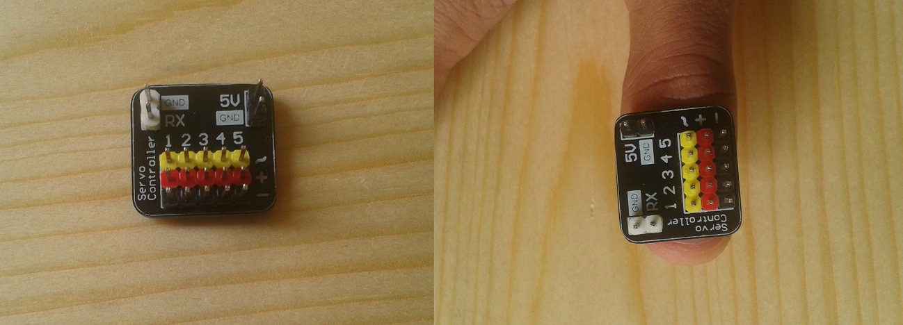
This design using single layer PCB (bottom layer only) and the firmware only has 0,1 ms resolution. As i build this for proof of concept only, when i have time, i'll update the firmware and the PCB with double layer so i can put led for power indicator and RX indicator.

The reason why i only using 0,1 ms is because the reliability for UART. The UART is very poor, its about 70% hit rate. So for using this, make sure you send the command at least 3 times. Its because this board only using internal clock, and bitbanging UART, since ATTiny13 does not has hardware USART/UART.

The UART technique is developed by Eric Evenchick. And if you take a look of his page you even can use Half-duplex software UART single pin operation for this module.

The command for this module only using UART. you can connect the RX pin to your arduino or other microcontroller TX pin.

It has 2 type of command. The first one is single update servo command, and the second one is for updating all servo on the same time.

If you playing with MeArm by Benjamin Gray you would using the second command for updating all the servo for pointing your MeArm to the point that you want instead of only one by one.

Because the firmware is beta version, you have to trial n error to add some delay for each character, so the communication miss rate is decreased (especially for 2nd command for updating all the servos).

This is the sample command communication for updating the servo :

1st type (single update servo command) :

sent_string("A10"); //sent servo A value
sent_string('!'); //sent command to move the servo
_delay_ms(200); //wait for servo movement 

using delay for reliable communication sample :

sent_string("A");
_delay_ms(1); //give a breath for the bit bang UART
sent_string("1");
_delay_ms(1); //give a breath for the bit bang UART
sent_string("0");
_delay_ms(1); //give a breath for the bit bang UART
sent_string('!'); //sent command to move the servo
_delay_ms(200); //wait for servo movement 
another sample :

//sent value for all servos and move the servos
sent_string("A10B15C10D20!");
/*from command above, if any miss communication of one or more servos value, the another value that received will be processed*/

2nd type (updating all the servo)

sent_string("A10B15C10D20*") //sent value for 5 servos and move the servos

/*
with asterisk '*' (star) command, if any missed value all servos will not executed
*/


nb:


  • 1 × ATTiny13 / ATTiny13A / ATTiny25 / ATTiny45 / ATTiny85 ~ about $1 any microcontroller that above or equal ATTiny 13 will works
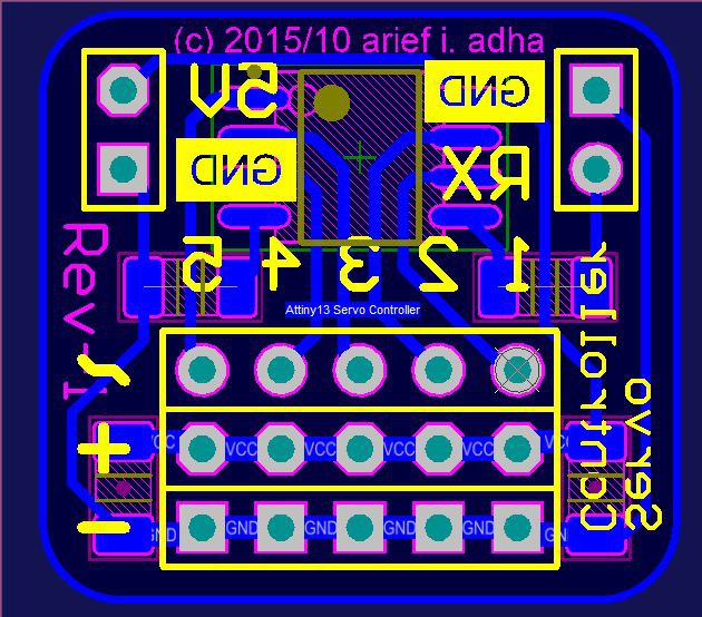
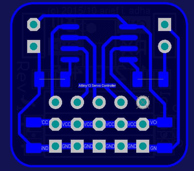
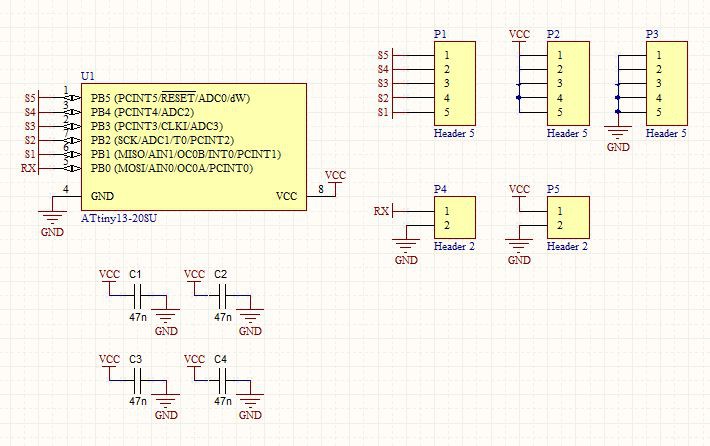
  • 1 × Board for ATTiny ~ less than $0.5 from break out board or bread board. look at schematic bellow for wiring. and also the greber file if you want to making like my board
  • 1 × Male Header ~ less than $0.2 color full headers will be awsome !!
  • 2 × 0805 SMD Capacitor ~ less than $0.1 get bigger value you can get
  • 2 × 1206 SMD Resistor 0Ω less than $0.1 if you using masking/silk screen you can short it with a big blop of tin or wire

View all 6 components

View all 2 project logs

  • 1
    Step 1

    Get your PCB first, but you can also using DIP style ATTiny and using your bread board and follow the connection from schematic above.

    If you have access to making a PCB this is the Gerber files or you can also using SOIC-break-out-board

  • 2
    Step 2

    Solder the chip according to this list of pin usages :

    PB0 : RX/TX purposes

    PB1 : SERVO A / SERVO 1

    PB2 : SERVO B / SERVO 2

    PB3 : SERVO C / SERVO 3

    PB4 : SERVO D / SERVO 4

    PB5 : SERVO E / SERVO 5 or RESET pin (disable from fuse bit to enable this channel but you can't program the chip with standard ISP programmer)


  • 3
    Step 3

    Burn the chip with this hex file and set the fuse bit to High 0xFF Low 0x7A (reset enable) or High 0xFE Low 0x7A (reset disable).

View all 3 instructions

Enjoy this project?

Share

Discussions

[deleted]

[this comment has been deleted]

arief ibrahim adha wrote 12/21/2015 at 04:57 point

Thank you :

  Are you sure? yes | no

Pete wrote 12/18/2015 at 16:59 point

The PCB traces don't seem to match the schematic.  Whereas the schematic shows four caps, it looks like two of the PCB pads are meant to be 0-Ohm resistors (for GND and RX connections to the uC).

I'd also recommend using much larger traces for the 5V and GND connections to the headers.  That would reduce trace resistance and possibly prevent burning off a trace if one of your servos draws a heavy current.

Otherwise, very interesting.  I like hacks like this...

  Are you sure? yes | no

arief ibrahim adha wrote 12/21/2015 at 05:05 point

yup, you are right thats not a capacitor, its a 0 ohm resistor acting for jumper, because this board only using single layer.

it has two zero ohm resistor on GND trace on pin power and RX trace.

the trace is might be small but enough for 9g servo, and this module not recomended for geavy current servo, since it has no fuse or regulator on it.

thanks btw for your response 


  Are you sure? yes | no

Rue Mohr wrote 12/12/2015 at 08:07 point

I think its possable, to go 9600 baud, 24000 counts/channel 5 channels, at 16Mhz... it would be crafty coding. I'll just stick to the atmega328 tho :) .... balancing the instruction count of the serial state machine would be a pita.

  Are you sure? yes | no

arief ibrahim adha wrote 12/12/2015 at 16:23 point

yay, you said atmega328 on 16MHz.... you don't say... as a maker that hiding on a word "why i make this? because i can" and "this is lowcost" also "there is fun to make something" attiny13 is just for fun tho... :) 

  Are you sure? yes | no

Rue Mohr wrote 12/12/2015 at 17:21 point

Your project it great, its hard to find good uses for the tiny13. I made a tiny13 analog to servo pwm converter, 2 channel, it works great for testing servos. I almost always use the m328 because I can buy them on a board with all the support circuitry for only $1.50ea

http://ruemohr.org/~ircjunk/tutorials/prog/servoControl2/

  Are you sure? yes | no

arief ibrahim adha wrote 12/13/2015 at 04:55 point

Yup you are right about the price... at my first attempt learning to design the electronic hardware i have to calculate what really i need, FLASH, RAM, etc. just like Dave (from EEVBlog said) real engineer does not stuck on one microcontroller, they can not be limited from the chips choices. BUT (just like you said) i forgot my high school economic class, that mass production can bring down the price. 

Now days ATTiny85 is way cheaper than ATTiny13. So do ATMega8 is way cheaper than ATTiny2313. And soon (already) ATMega328 is way more cheaper than all those chips. I was doomed with my design and beating by economic concept. ATMega328 is most popular chips on the market i believed, since Arduino hooked up those chips.

And for my real project i search the price first than looking up for what i need :doh: smash down my ideology. Those chips are going extinct btw...

any links maybe for those $1.5 ATMega328 really appreciate :)


  Are you sure? yes | no

Rue Mohr wrote 12/13/2015 at 18:52 point

They can be obtained cheaper, but I like

http://www.aliexpress.com/item/8pcs-X-High-quality-Pro-Mini-328-Mini-3-3V-8M-ATMEGA328-ATMEGA328P-AU-3-3V/32528725646.html

If you can make out the dual row of pins on the one end, 6 of those are an ISP header (its all marked on the bottom of the board, which they don't show), as I don't use them as an arduino, this allows me to program them with my regular avr programmer.

I usually see prices between 1.75 and 2.50  ( USD :(  )

If your interested, I have code that will turn one into a 8 channel 'SSC'-like servo controller, 24000 position counts/channel, ~60Hz update. most importantly, the timing is super stable, no jitter!

  Are you sure? yes | no

arief ibrahim adha wrote 12/15/2015 at 08:49 point

wow thats was hard rock prices LOL.... thanks but no need controlling a servo is a piece of cake. and update rate is limited by clock. and i like to write my own code :)..

thanks btw for the link..

  Are you sure? yes | no

Craig Hissett wrote 12/11/2015 at 14:27 point

I'd love some of these

  Are you sure? yes | no

arief ibrahim adha wrote 12/12/2015 at 03:54 point

thanks, if any missing files, or any extension files that you need just let me know. btw sorry for poor english. 

  Are you sure? yes | no

deʃhipu wrote 12/11/2015 at 10:45 point

Wouldn't it be better to use a protocol that doesn't rely on synchronized clocks, such as I²C?

  Are you sure? yes | no

arief ibrahim adha wrote 12/11/2015 at 11:21 point

well that's pretty neat idea to using I²C for reliable data transmission, but I²C using 2 pin, while UART only 1 pin, regarding attiny has very limited i/o pin. Let say i need the reset pin, its only left 5 i/o pin, 2 pin used for I²C, and i can only use 3 servos. But if i using UART, i can use 4 servo which MeArm using 4 servos. 

But I²C its good for project thats only using 3-4 servos and need a reliable data transmission.

But, if i send 3-4 times is just enough for me, and i could also add some delay on every character i send for more reliable data transmission.  if i need more realiable data transmission i'll using another microcontroller that capable of.


Beside of that i believe the miss rate is causing by internal clock, and power consumption by the servo. (I have to analyze it next time) because i see some drop voltage while executing, that's why if i enabling brown-out detection to 4.3V it will failed. :doh: i need a better 5 volt adapter for this, since i'm only using ~1A wall adaptor.


And if i take a look for the USART/UART files, it seems using UART (asynchronous receiver/transmitter that doesn't rely on synchronized clocks) not USART.
2nd decision, i need to debugging the firmware, with UART i can easily monitoring via terminal :)

  Are you sure? yes | no

deʃhipu wrote 12/18/2015 at 13:02 point

Hmm.. how about a protocol similar to what those addressable LEDs use? Short pulse is zero, long pulse is one? You could even have two-way communication this way.

  Are you sure? yes | no

arief ibrahim adha wrote 12/21/2015 at 05:13 point

yes it might be work, feel free to use this board for your own firmwire. its open source btw.

and with my protocol you can also use for 2 comunication, its half duplex UART as i mention above http://hackaday.com/2014/01/13/software-half-duplex-uart-for-avrs/

the benefit from UART you can simply use hyper terminal from computer or your bluetooth without any software debugging needed. and also can give you character feedback like "OK" to indicate all the data transmitted (ACK)

and i don't thing LED protocol can give 2 way communication, if i push the program using wait for the pulse it must have RTO (request time out) protocol. so the 2 devices know each other when to transmit and when to receive. 

thank you btw for your advice :)


  Are you sure? yes | no

Similar Projects

Does this project spark your interest?

Become a member to follow this project and never miss any updates