After some time of thinking about different configurations (RGB LEDs or single color? and size) there is now a more sable of idea of this project. older thoughts on this project you can see in the first logs.
Hardware
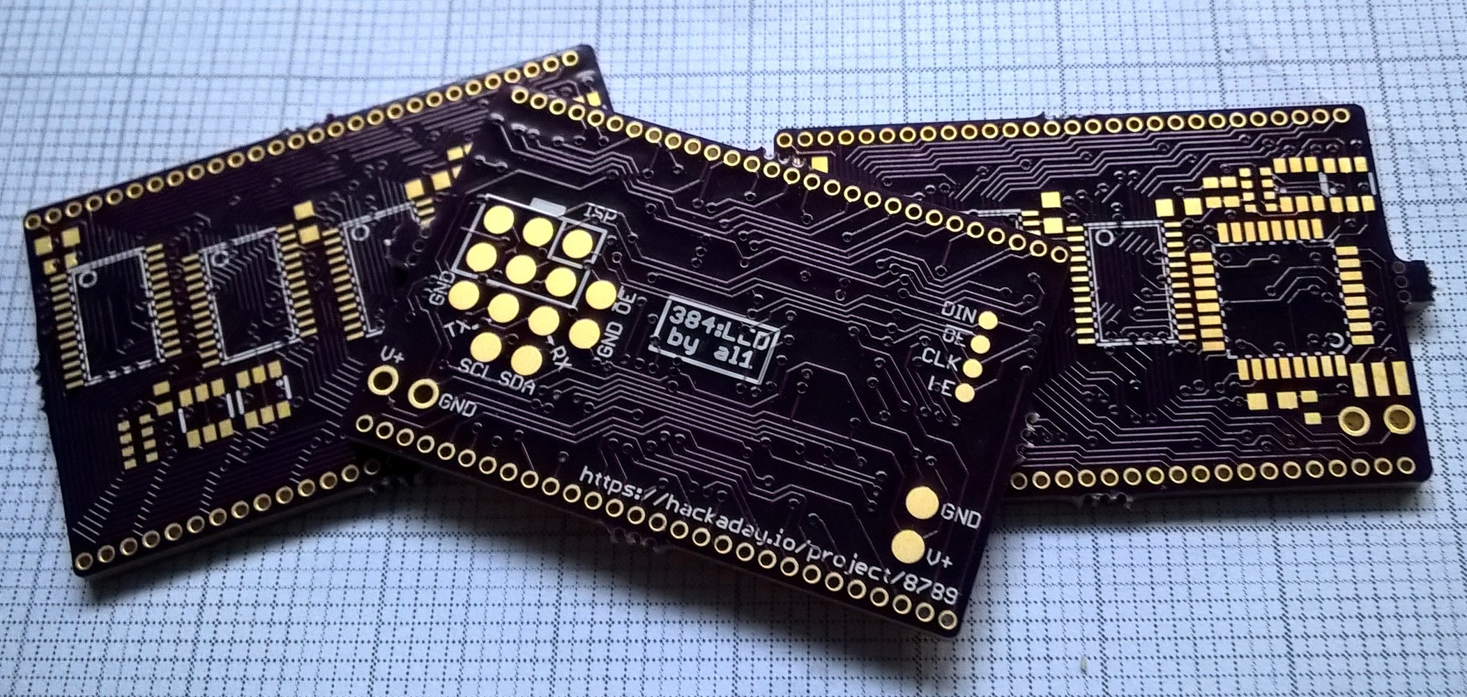
For this project I designed two PCBs. A control PCB and a LED PCB. My goal was to fit them both in a small panel inside a 5x5 cm square to use cheap Chinese Manufacturing offers. Both PCB to have the same size and will be connected with 50mil / 1.27mm pin headers. The LED PCB will be stacked on top of the control PCB.
LED PCB
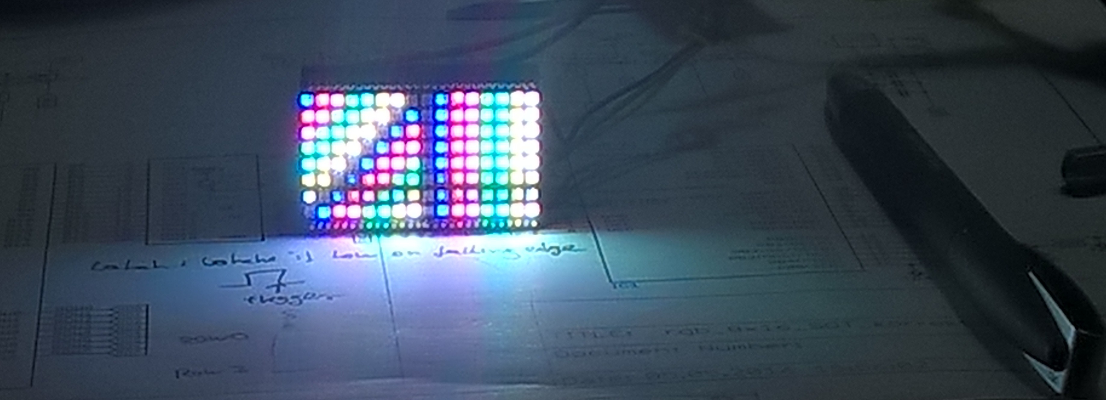
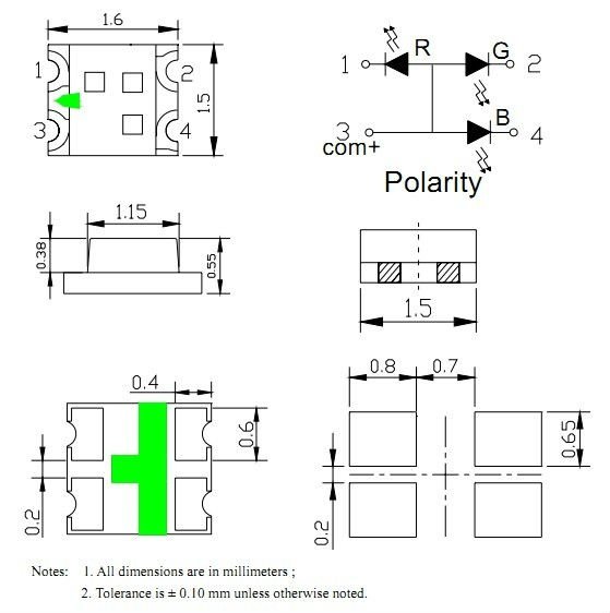
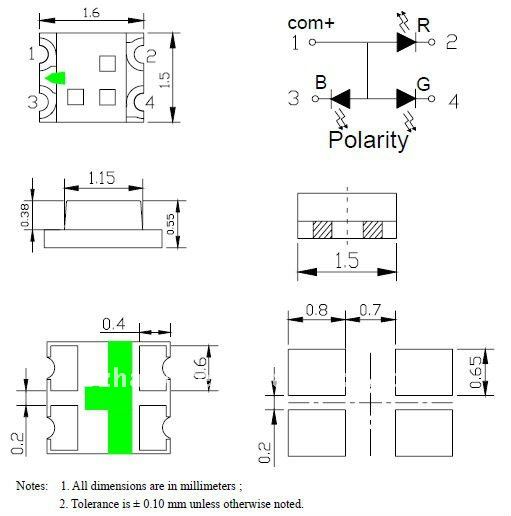
On the LED PCB you will just find the 0404 SMD RGB LEDs. All columns and rows are accessible via the pin headers at the sides. The LEDs are common anode. So the eight rows are the anodes (plus) and you have 16x3 = 48 (16 columns by 3 colors) connections for the cathodes (minus). All led driving and current limiting happens on the control PCB.
Control PCB
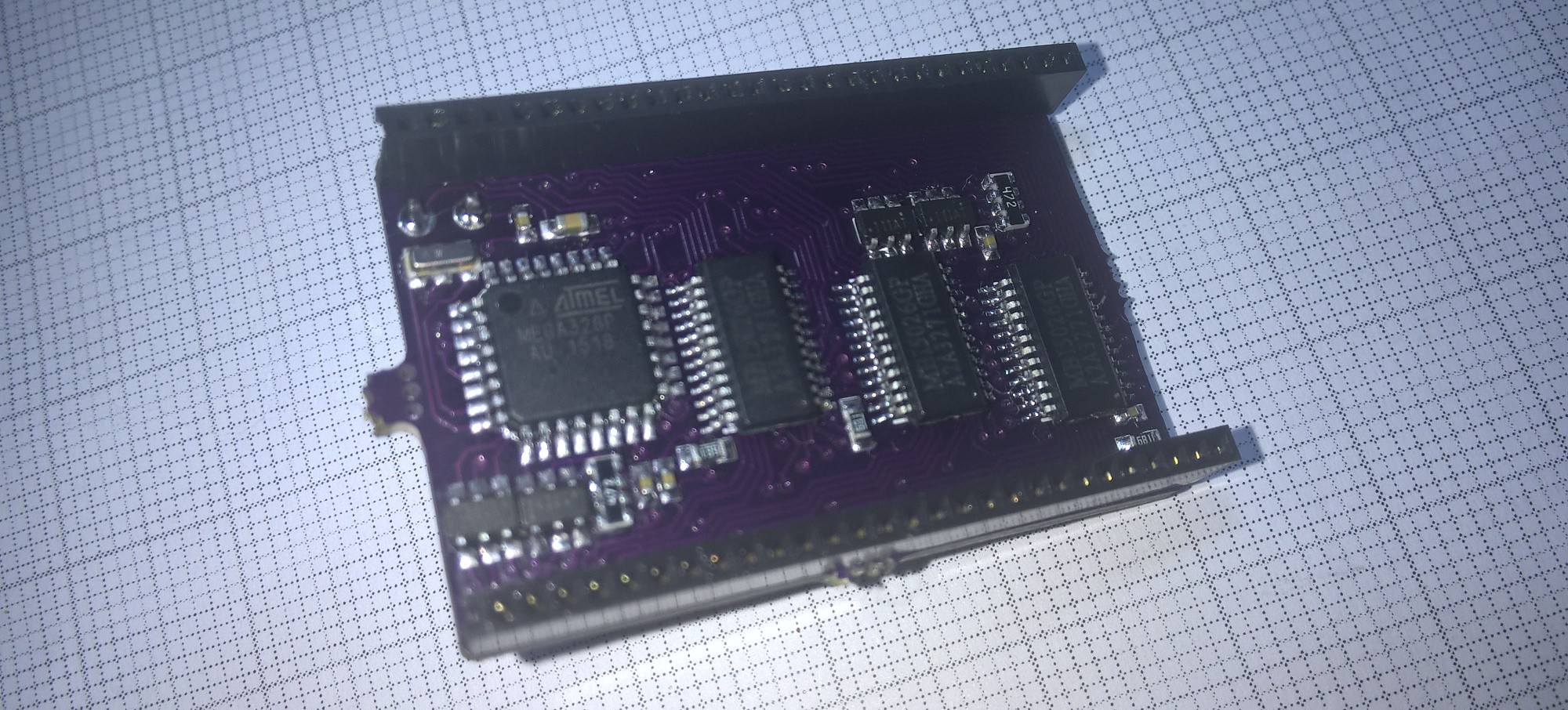
On the control PCB you will find everything to drive the LEDs. I will use three (one for each color) 16bit LED sink driver. The current of this drivers are set by only one resistor and they are controlled like shift register. I will use MBI5026 but there are many compatible drivers available (for example MAX6971 or SCT2024CSSG).
The rows are controlled by discrete P-channel mosfets. To reduce the space needed I will use dual Mosfets.
On the control PCB there I also a Microcontroller. I will use a ATmega328p. The ATmega controls the LED sink drivers via its SPI interface and the row Mosfets via eight IO lines. There are connections for UART and i2c to get some data into this later.
Software
...
Errata
- AVCC of the Atmega should be connected to VCC, because it powers needed IO-pins. I fixed this with a wire
- When using the hardware SPI in Master mode, the MISO pin is always input. But on the PCB it was used as for the latch output. I fixed this by connecting MISO with SDA (both available on a test pad) and using the SDA pin for the Latch output.
Notes
Possible dual p-fets:
| Part | I_D [-A] | R_ON ( -4.5V) [mΩ] | R_ON ( -2.5V) [mΩ] | R_ON ( -1.8V) [mΩ] |
| Si3993DV | 1.6 | 245 | ||
| Si3911DV | 2.2/1.8/1.5 | 145 | 200 | 300 |
| IRF5810 | 2.9/2.3 | 90 | 135 | |
| BSL308PE | 2 | 130 | ||
| BSL314PE | 1.5 | 230 | ||
| NTGD3133P | 2.2/1.6 | 145 | 200 | |
| FDC6306P | 1,9 | 170 | 250 |
-
 Alex
Alex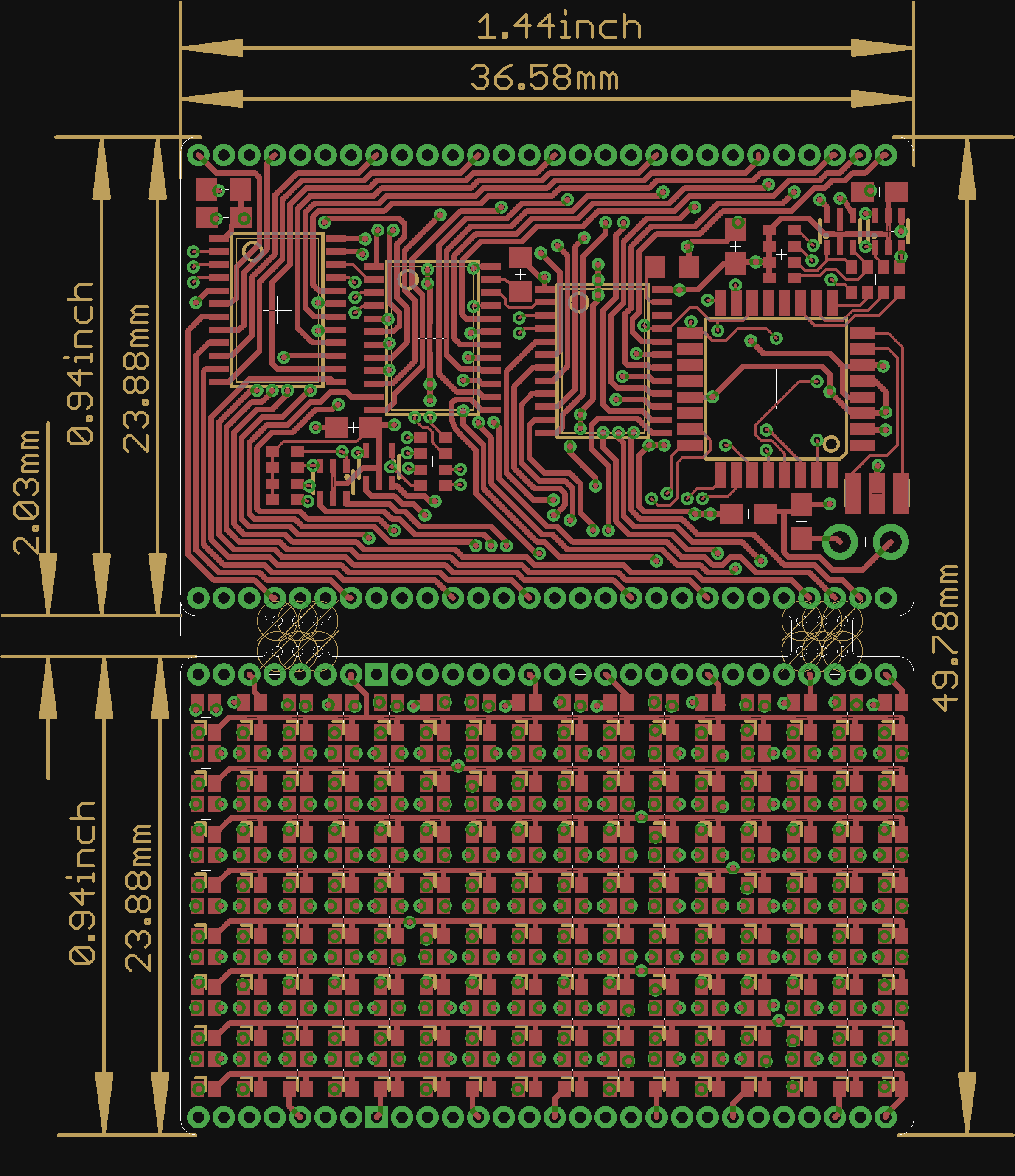




 Yann Guidon / YGDES
 gokux
gokux
 Sam Ettinger
Congrats on so many great LED projects - lots to learn from here! Btw, there was side discussion elsewhere if LEDs could be used as diode ROM memory (connecting decoded rows (address) to columns (word bits)). Asking the LED expert here if that is feasible?