Alex
Alex-
First Animation
06/15/2016 at 17:57 • 7 commentsSome first basic rainbow animation is now running as a demo:
![]()
The video is also in better quality in the Youtube Playlist.
-
PWM for global brightness
05/16/2016 at 18:45 • 0 commentswith 100% brightness this display is very bright. To change that I added a PWM signal to the output enable line of the drivers. This PWM signal must be faster than the line scanning. Therefore I used only a three Bit PWM, which give me eight brightness steps. The main benefit is, that at least on the lowest brightness it is now also easy to take pictures of it. Here a short video of sweeping tough the brightness.
-
we got color
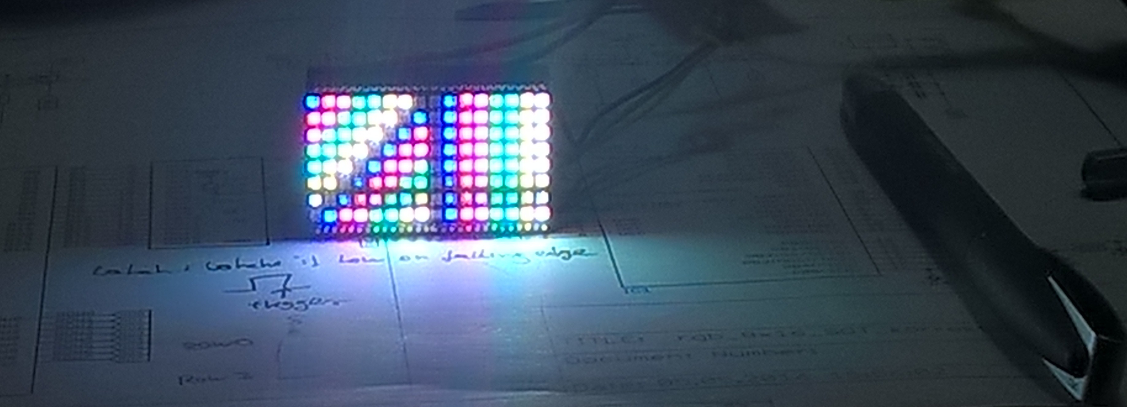
05/09/2016 at 21:25 • 4 commentsThe multiplexing finally works! The Matrix can now show images saved in RAM. Per pixel 8 Bit are used (RRRGGGBB). Here is a image of the result:
![]()
photographing this is not easy because of the multiplexing. This can be also seen in this image by the different brightness of the lines. But the human eye is worse then this camera. So you do not see it.
The image "file" for that looks like this (I used some defines for the color values):
{ {WHITE, YELLOW, CYAN, GREEN, PINK, RED, BLUE, BLACK, ...},
  {WHITE, YELLOW, CYAN, GREEN, PINK, RED, BLUE, BLACK, ...},
  {WHITE, YELLOW, CYAN, GREEN, PINK, RED, BLUE, BLACK, ...},
  {WHITE, YELLOW, CYAN, GREEN, PINK, RED, BLUE, BLACK, ...},
...};
compared to the file extract, the display is rotated by 180° on the image. I should really mark the upper right corner somehow to make the images right orientated.
-
Soldering and first testing
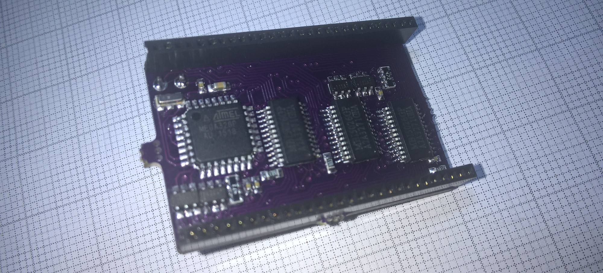
05/05/2016 at 19:39 • 3 commentsThe first PCB is soldered now. Every thing does fit.
![]()
During soldering and the later Testing I found some mistakes in the Schematic:
- AVCC of the Atmega should be connected to VCC, because it powers needed IO-pins. I fixed this with a wire
- When using the hardware SPI in Master mode, the MISO pin is always input. But on the PCB it was used as for the latch output. I fixed this by connecting MISO with SDA (both available on a test pad) and using the SDA pin for the Latch output.
For testing I wrote some firmware to sweep through all LEDs. The result can be seen in this little video:Next I will write some more advanced firmware.
-
new control PCB arrived
05/04/2016 at 16:27 • 0 commentsThe new control PCB arrived. Now the SOT23-6 P-fets do fit on the PCB. Will solder one soon.
![]()
-
what happend to the tiny 0404 RGB LEDs?
04/24/2016 at 12:57 • 0 commentsI an earlier log I did show a image of these tiny 0404 RGB LEDs. These LEDs were not the right for the footprint I used in this project. But I started I new project with the 0404 LEDs. Pleas take a look at #192:LED. If you want to see what will/could happen to this LEDs And pleas like or follow it.
-
new LEDs are working & new control board layout
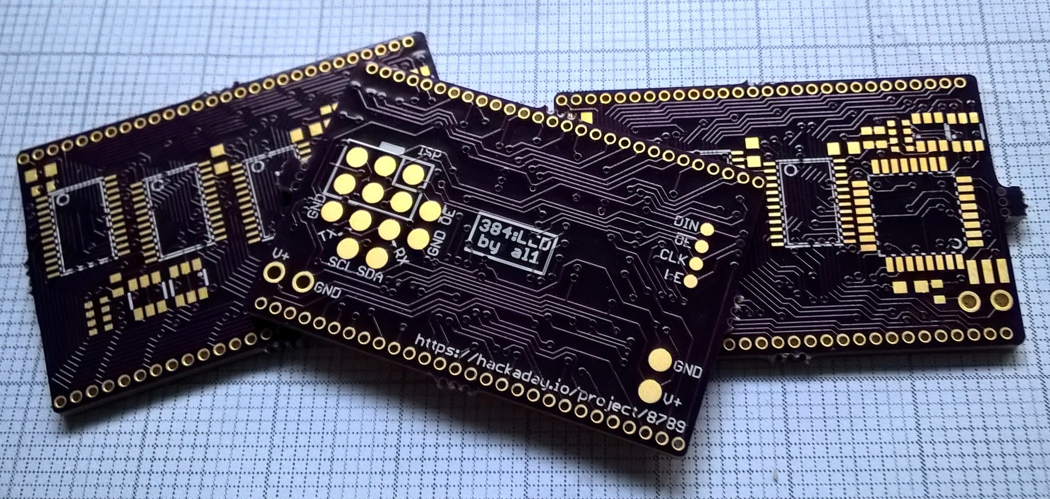
04/17/2016 at 18:09 • 3 commentsThe new LEDs are the right ones. Now at least the LED PCB do work. Here is a picture of the soldered LED PCB:
![]()
I also redesigned the control PCB: Now the bigger SOT23-6 Transistors do fit and it is inside of OSH-Park's Manufacturing specifications. The new board for the contol PCB are already orderd. So I hope I will have a first working prototype soon.
-
somehow this project is doomed .. or I do not carefully enogh check footprints
04/06/2016 at 19:38 • 7 commentsI last logs I wrote about two errors and how I thought I would could fix them. But now the errors did strike back. I think it was mostly may fault.
First the p-fets. Well TSOP6 is the same as SOP23-6. Could have noticed that. I would need TSSop6 to use the original boards. But in TSSOP6 you do not get the footprint I needed. So the controller board is not fixed.
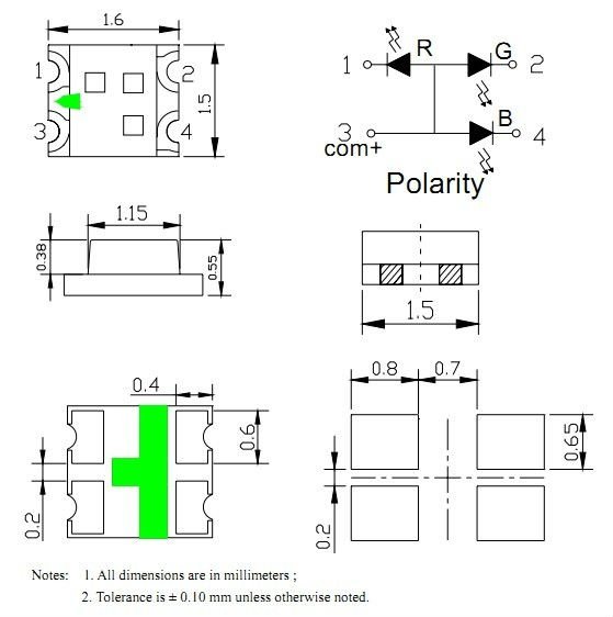
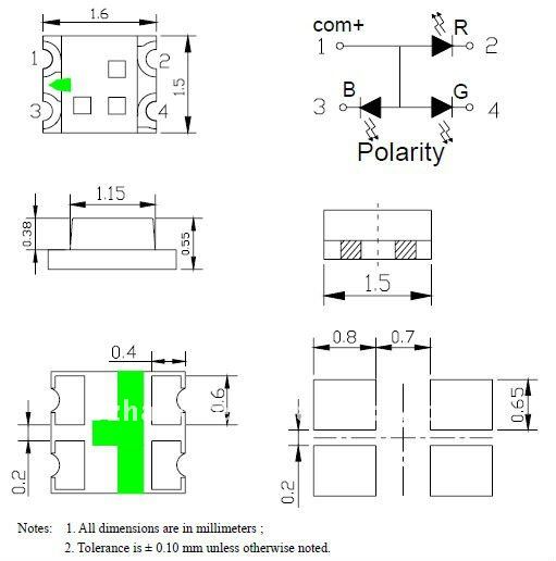
Second the LEDs. There are two different pinmaping schemes for it. I I did order the wrong. Well that is what happend if you sort them by price on aliexpress. Here are two pictures from aliexpress:![]()
![]()
Different position of the common Anode Pin!
ill now try to get the right LEDs. And in parallel redesigning the controller board. If the new LEDs do work I will order only a new controller board. If not I will maybe order both new (or abort this project out of frustration).
-
LED footprint fail is not so bad
03/18/2016 at 20:08 • 2 commentsIn the last log I did wrote that I did used the wrong footprint for the LEDs. Well it is more the wrong LED for that footprint. The footprint was not a wrong invalid size, I did only used one for a little bit bigger LED. So I do not need to order/design new boards. Ordering new LEDs is cheaper and probably also faster. So both erros are solved by ordering fitting parts.
-
double fail
03/17/2016 at 22:49 • 0 commentsThe PCBs did arrived today. But there are two errors in my design, which I should have noticed. First the footprint of the p-fets is wrong. SOT23-6 is much bigger than TSOP6. This error could be fixed by getting other p-fets, but the second error is wore.
Double checking footprints of cheap Chinese LEDs seemed to be not enough. After some frustrating soldering I did noticed that I did used the wrong footprint for the LEDs. Some how I did make them to big. So it is very difficult to solder all four pads with contact.
So how will it go on? I will redesign the PCB. Mostly I will just change the LEDs footprint I think. and I will get right p-fets. In this way I need only new LED PCBs.
384:LED
Mini (1.44'' x 0.94'' or 24mm x 37mm) 8X16 RGB LED Array. 128 RGB LEDs with three LED chip each gives 384.