-
1Step 1
The analog circuitry
One of the digital pins of the microcontroller is programmed with a square wave using the tone() function, this drives the ultrasound transmitter. It is a lower voltage than usual for driving a piezoelectric transducer but enough in this case, since we are not range-finding and looking for low amplitude echoes.
On the receiver side, it is possible to directly digitize the ultrasound signal using the Teensy 3.1, making use of the fast ADC library from Pedvide. Then the amplitude can be determined from fitting the signal or taking a FFT. However, it is much easier to rectify the voltage using a germanium diode and low pass filter the output with a RC filter. Then the ADC can directly read out the amplitude of the signal.
![]()
-
2Step 2
The stepper motor and stepper motor drive
I am using the stepper motor that originally translated the sled in the optical drive. See the project by esot.eric for a nice resource on repurposing optical drives. Our drive has 20 full steps per revolution. It is being driven by the EasyDriver which defaults to 8 microsteps, giving 160 microsteps per revolution. The EasyDriver is set to its minimum current of about 150 mA.
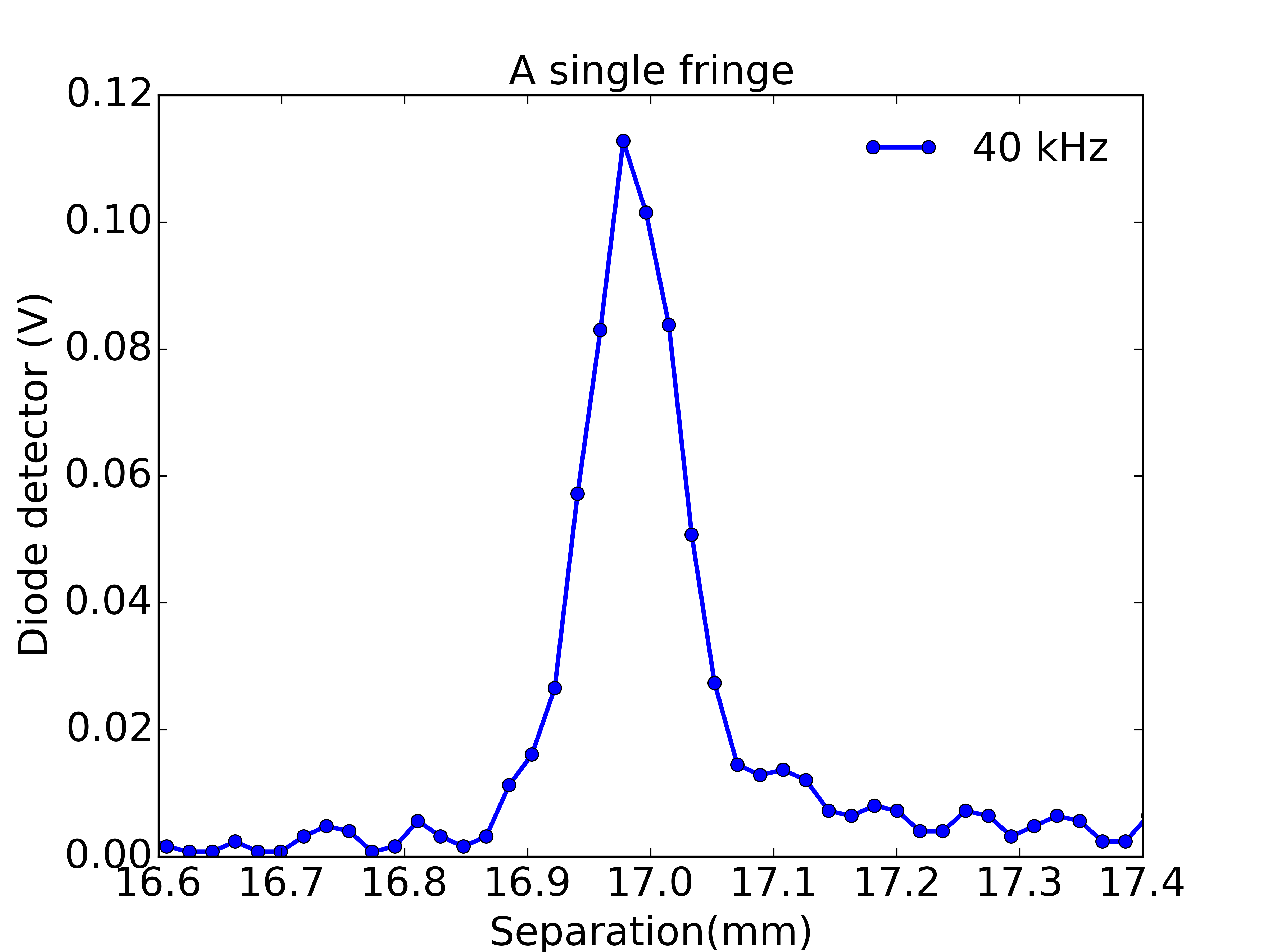
The helical pitch of the leadscrew attached to the motor is close to (and perhaps exactly) 3 mm, giving 18.5 microns displacement per microstep. By the way, does anyone know how many microsteps are used with similar steppers in a real optical drive?
It turns out that this is a pretty useful resolution for the spectrometer, though I would be happy for a bit more... In the figure below, the ADC is being read each microstep over a single interference maxima. You can see about 10 data points per fringe.
![]()
Standing waves of sound
An ultrasonic interferometer is assembled from optical drive components, 3d-printed parts and an ultrasonic range-finder.
 Andrew Ferguson

Discussions
Become a Hackaday.io Member
Create an account to leave a comment. Already have an account? Log In.