Andrew Ferguson
-
Motivation for an IQ detector in the ultrasonic Fabry-Perot
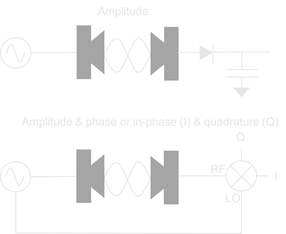
09/28/2016 at 20:07 • 0 commentsReading Ronald Quan's nice book 'Build your own transistor radios' inspired me to improve the detection circuitry on the ultrasonic Fabry-Perot (UFP). My first experiments had diode-detected the amplitude of the transmitted ultrasound signal through the semi-transparent mirrors. This approach is fine, though I was worried about the linearity of the diode, and it relates well to the optical case where intensity of transmitted light is usually detected.
However, a defining characteristic of any type of wave is phase and if we purely measure amplitude or intensity we ignore this important information. We can do better by using a frequency mixer to determine both the amplitude and phase, or equivalently the in-phase and quadrature components of the transmitted wave. To see that these measures are equivalent, recall that a sinusoid with a phase shift can be decomposed into a sin and cos with specific amplitudes.
Below are schematic drawings of the two detection approaches and over the next couple of posts I will show how an IQ measurement is implemented in the UFP by using the Tayloe detector, a commonly used detector in software defined radios.
![]()
-
Ultrasound amplifier PCBs
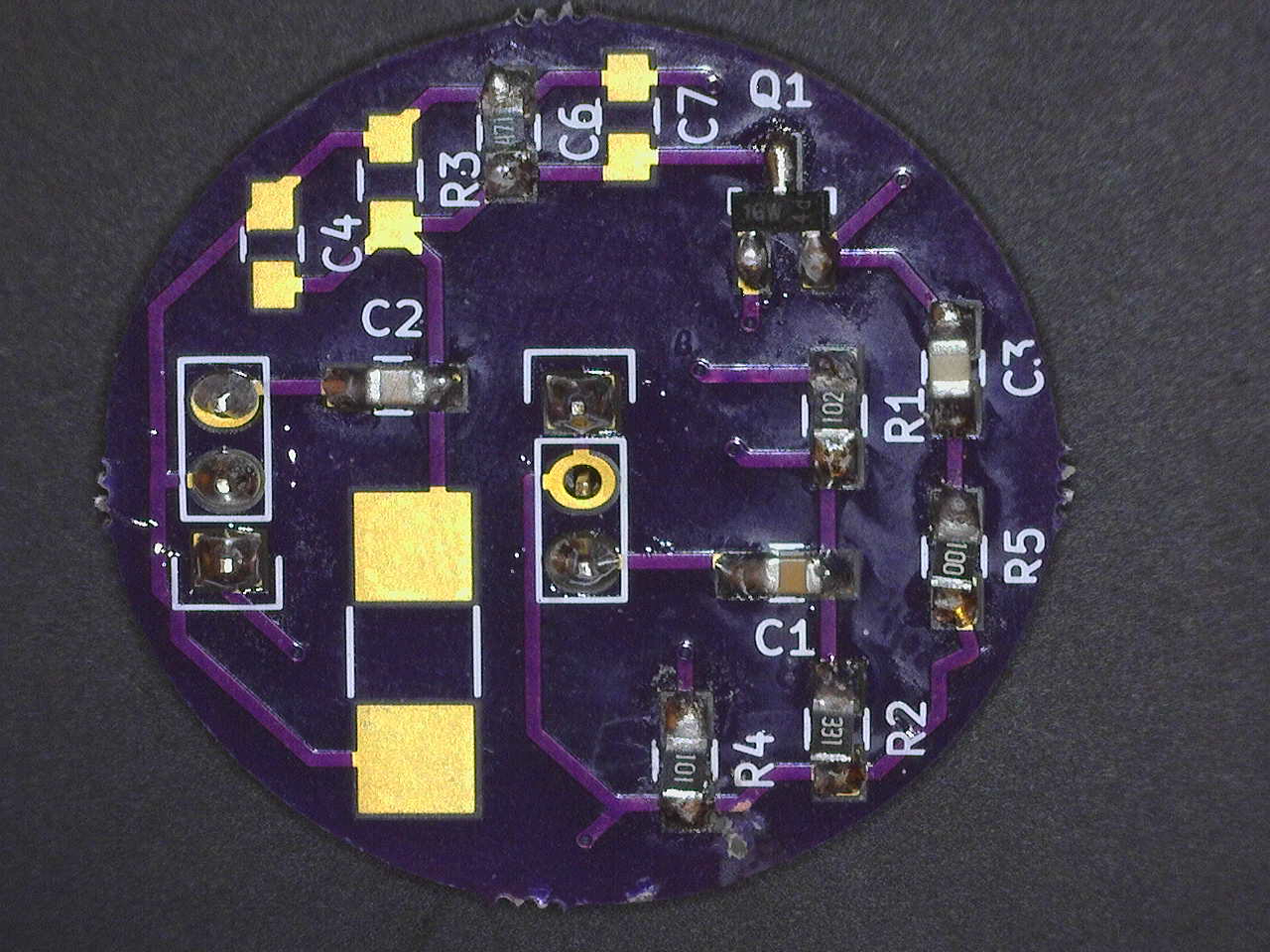
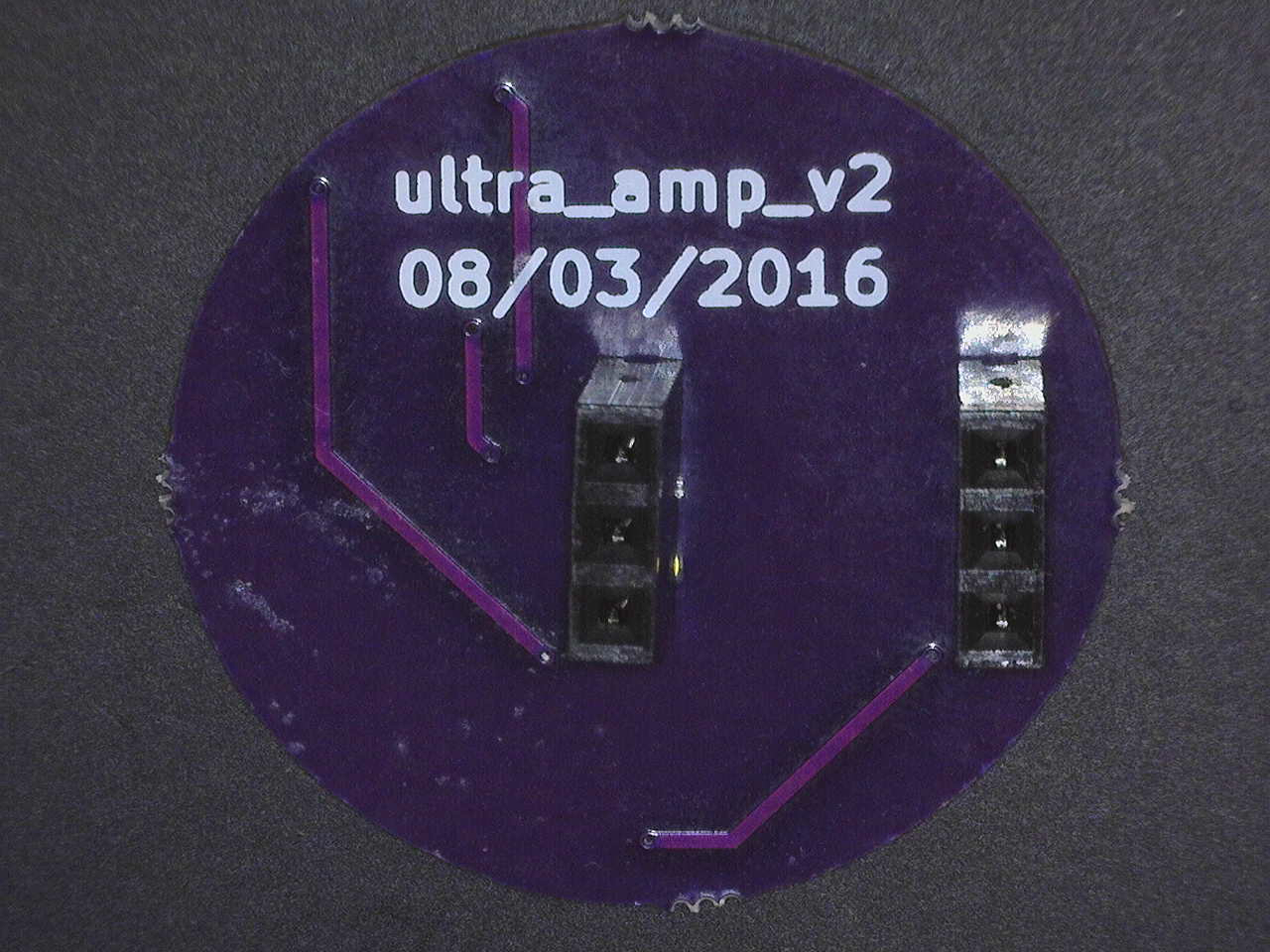
04/02/2016 at 20:22 • 0 commentsAfter breadboarding the amplifier for the ultrasound signal and seeing that it worked fine I decided to get some PCBs made from OSH Park. Here's a picture of the soldered up PCB which still consists of a single transistor common emitter amplifier. The reason it is a 1 inch diameter circle is that it will be directly soldered onto the ultrasound transducer and look prettier that way. There are some unsoldered parts here because I want to play with making it a tuned amplifier, by having a parallel resonant circuit as the collector load, but I didn't test this yet. The input pins are in the middle and the output and power pins to the left. The transistor is a BC847 in a SOT23 package, chosen since it is a general purpose npn bipolar. The resistors and capacitors are in 0805 packages.
![]()
![]()
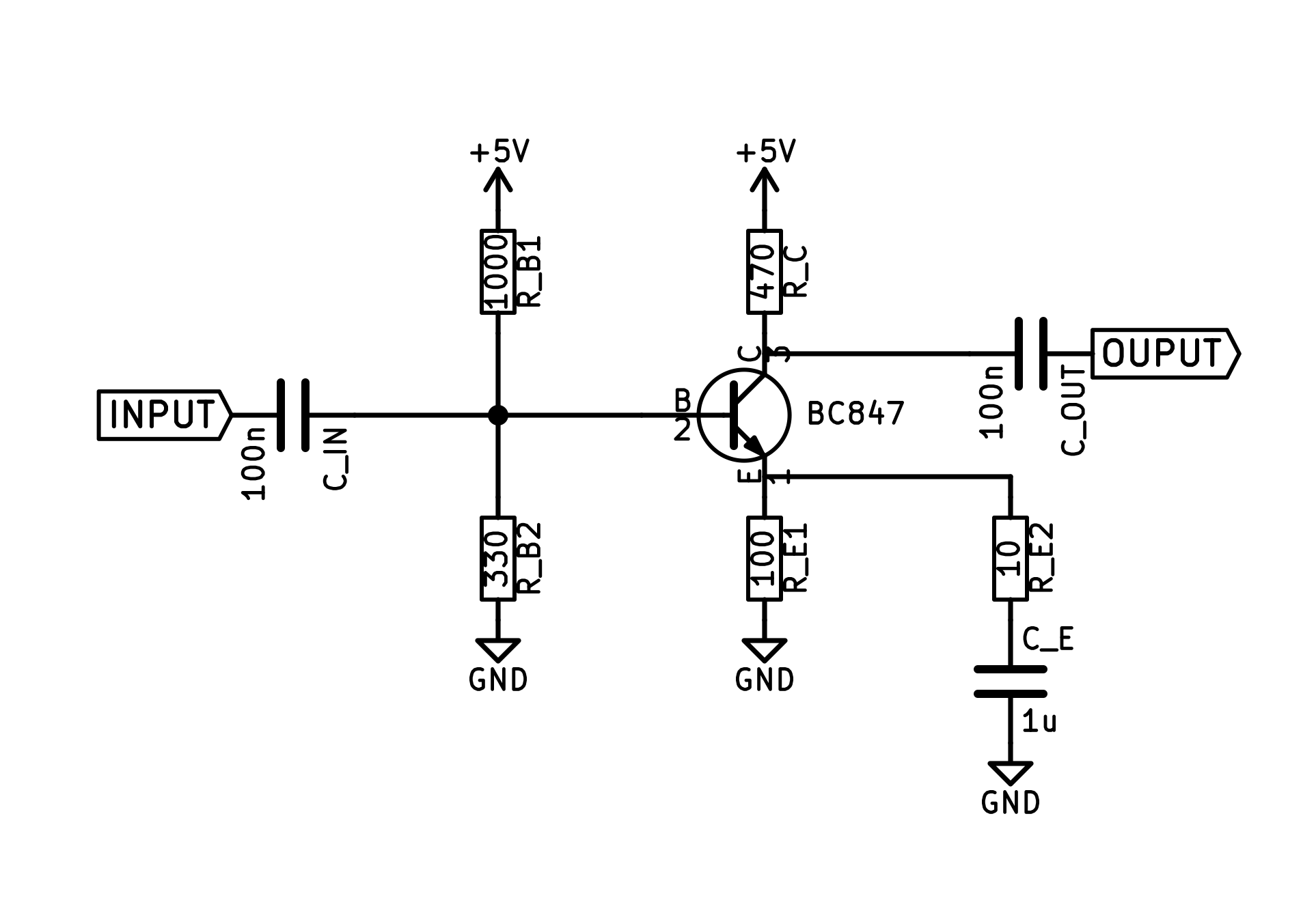
The circuit diagram is as follows, I changed the degenerated emitter to include a resistor (R_E2) in series with the bypass capacitor (C_E) as I hoped this would give me more predictable gain.
![]()
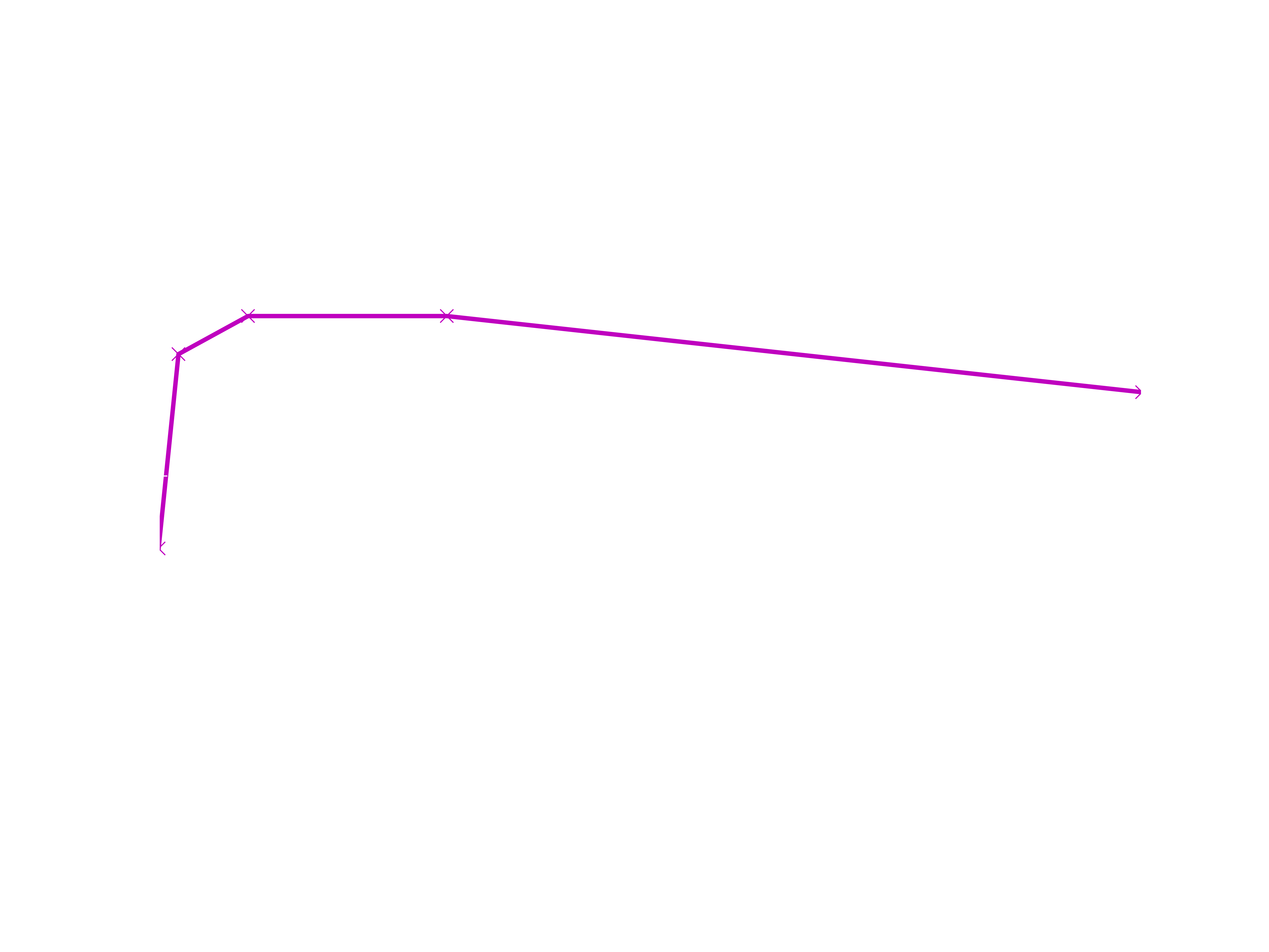
The measured gain is as follows, for an input amplitude of 10 mV. Gain compression starts to occur at an input amplitude of 50 mV, much more than I am expecting from the ultrasound receiver. I'm still pretty happy with this design which is now giving a voltage gain of 28 at 200 kHz (the transducer frequency) and next will play with tuning the collector load to reduce out-of-band noise.
![]()
-
Latest interference fringes
02/23/2016 at 19:56 • 0 commentsI just wanted to show some interference fringes using both the following:
1: The Si5351 as the oscillator - driving the ultrasound transmitter.
2: The single transistor amplifier (described in the previous log entry) amplifying the receiver signal, before envelope detection.
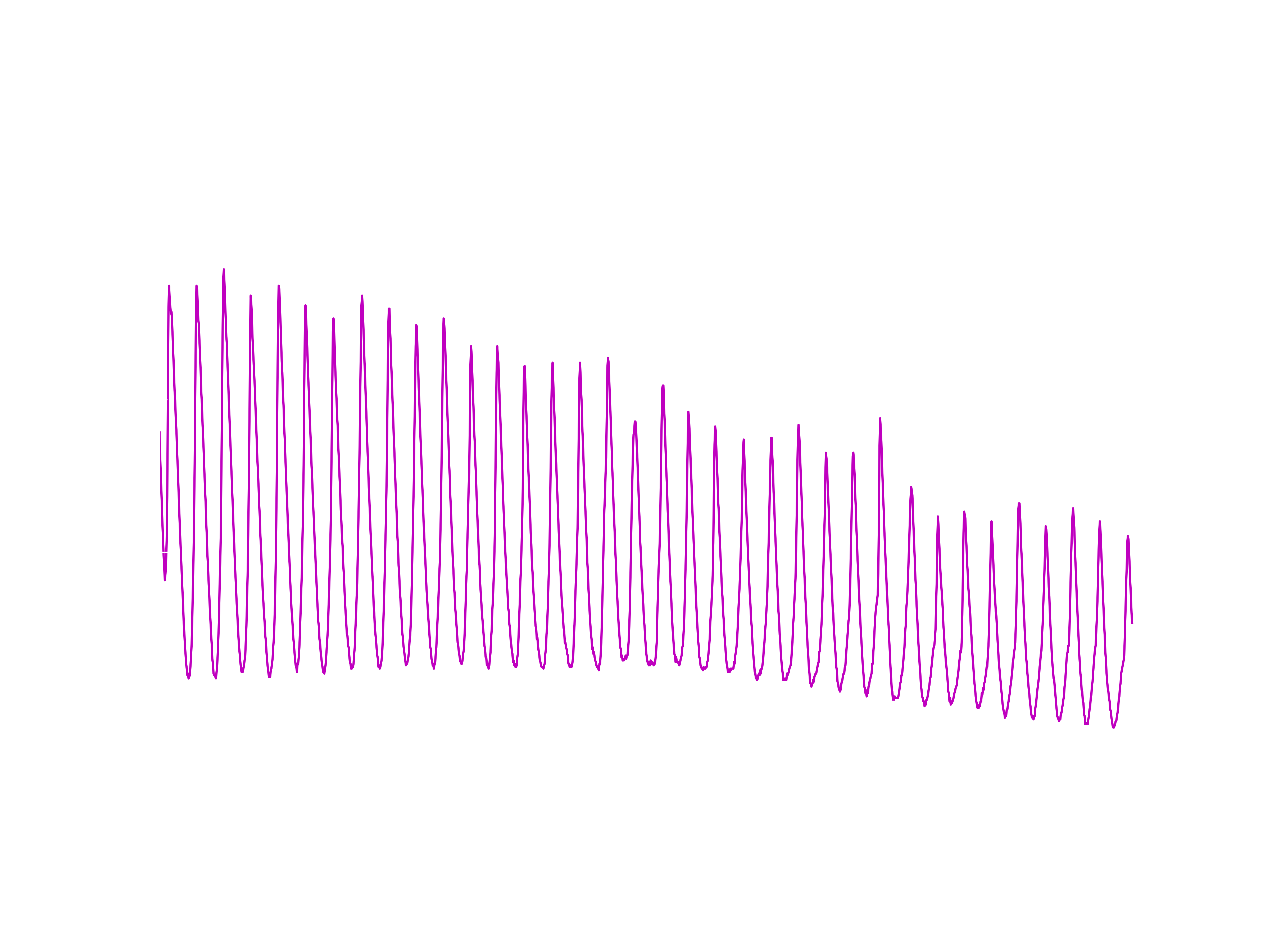
I think it is pretty awesome that these are interference fringes of sound and we are seeing up to about the 54th maxima.
![]()
-
An amplifier for the ultrasound receiver
02/20/2016 at 21:42 • 0 commentsI am looking to boost the 200 kHz signal from the ultrasound receiver from 10's of mV towards 1 V, so that when it is demodulated I fill the UNO's ADC range (presently set to 1.1 V) with as much signal as possible.
At work, I use several different types of amplifier and, via the usual arguments, it doesn't make sense for me to build them. At home, the solution to the buy or build equation is biased differently, so I get to make my first amp...
For simplicity, the design will be an AC coupled, single stage common emitter amplifier using a NPN transistor.
First considering the caps, I have some 100 nF polys at home and their reactance at 200 kHz is 8 Ohms, so these should work OK at the input and output.
A reasonable V_B seems to be about 1.2 V, so this gets set with a voltage divider consisting of a 1k Ohm and 330 Ohm resistor. Unfortunately I didn't measure the impedance of the transducer yet, but I think it will be somewhere between 100 and 1000 Ohms, so the resistor values seem sensible.
Guessing the base-emitter voltage drop to be 0.6 V, we then have a V_E of 0.6 V. For no particularly good reason, except that I don't want the output impedance to be too high, I chose R_E = 100 Ohms. This means that I_E is about 6 mA, allowing us to choose R_C = 470 Ohms, so that V_C is close to 2.5 V.
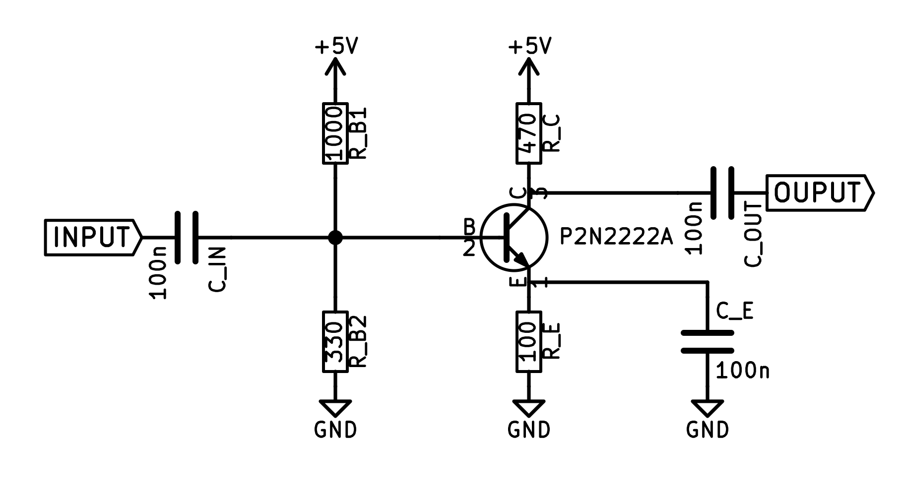
The emitter resistor is going to be bypassed with a 100 nF cap to give us a sensible voltage gain of about g=470/8= 59 at 200 kHz. The final circuit looks as follows and let's see if it works as expected.
![]() So, here is a time trace of the input to the amp (from the ultrasound transducer) as well as the amp's output. It has gain! In fact, the voltage gain is 47, so the simple calculations turned out to be not too bad. And, the output signal is of about the right amplitude. I am delighted, this amp is just what is needed.
So, here is a time trace of the input to the amp (from the ultrasound transducer) as well as the amp's output. It has gain! In fact, the voltage gain is 47, so the simple calculations turned out to be not too bad. And, the output signal is of about the right amplitude. I am delighted, this amp is just what is needed. ![]()
My to do list:
1: Move this circuit off the breadboard.
2: Put a parallel resonant circuit as the collector load, so as to make this a tuned amplifier, rejecting out of band signal.
3: Measure the impedance of ultrasound transducer and tune input impedance of amplifier to match this.
-
Checking out the transducers - impulse response
01/30/2016 at 22:15 • 0 commentsI wanted to have a look at the frequency dependence of the ultrasound transducers, separately from the ultrasonic Fabry-Perot (UFP). Here, I subject the transducer to a single 2 us pulse generated by Timer 1 on the UNO and look at the time domain response with a Rigol scope. Immediately after applying the pulse it is essential to send the drive pin to a high-impedance state with pinMode(X,INPUT), otherwise the transducer response is damped out almost immediately.
![]()
The Fourier transform is probably more useful and shows at least a pair of modes at around 200 kHz, where the transducer is specified for operation as a transceiver. There is also a much more significant mode at about 270 kHz, which will be worth looking at with the UFP.
![]()
It will be interesting to discuss this behaviour in terms of the equivalent circuit of the transducers but I will have to leave that for another time.
-
A new oscillator in the interferometer - the Si5351
01/28/2016 at 21:02 • 2 commentsPreviously I was using a timer generated square wave (f=200 kHz, Vpp=10 V) to drive the ultrasound transmitter. However, noise (perhaps timing jitter) in this oscillator was broadening the interference fringes, so I was looking for a better drive. In my first attempt to replace the oscillator I picked up a Si5351 chip on a breakout board from Adafruit. This chip outputs up to 3 square waves with Vpp=3.3 V, at frequencies between 2.5 kHz and 200 MHz. Here is the first data which look promising but, as you can see, I now need an amplifier on either the source or the detector side, since the reduced drive amplitude is only giving a 10 mV signal at the detector.
![]()
-
Oscillator noise
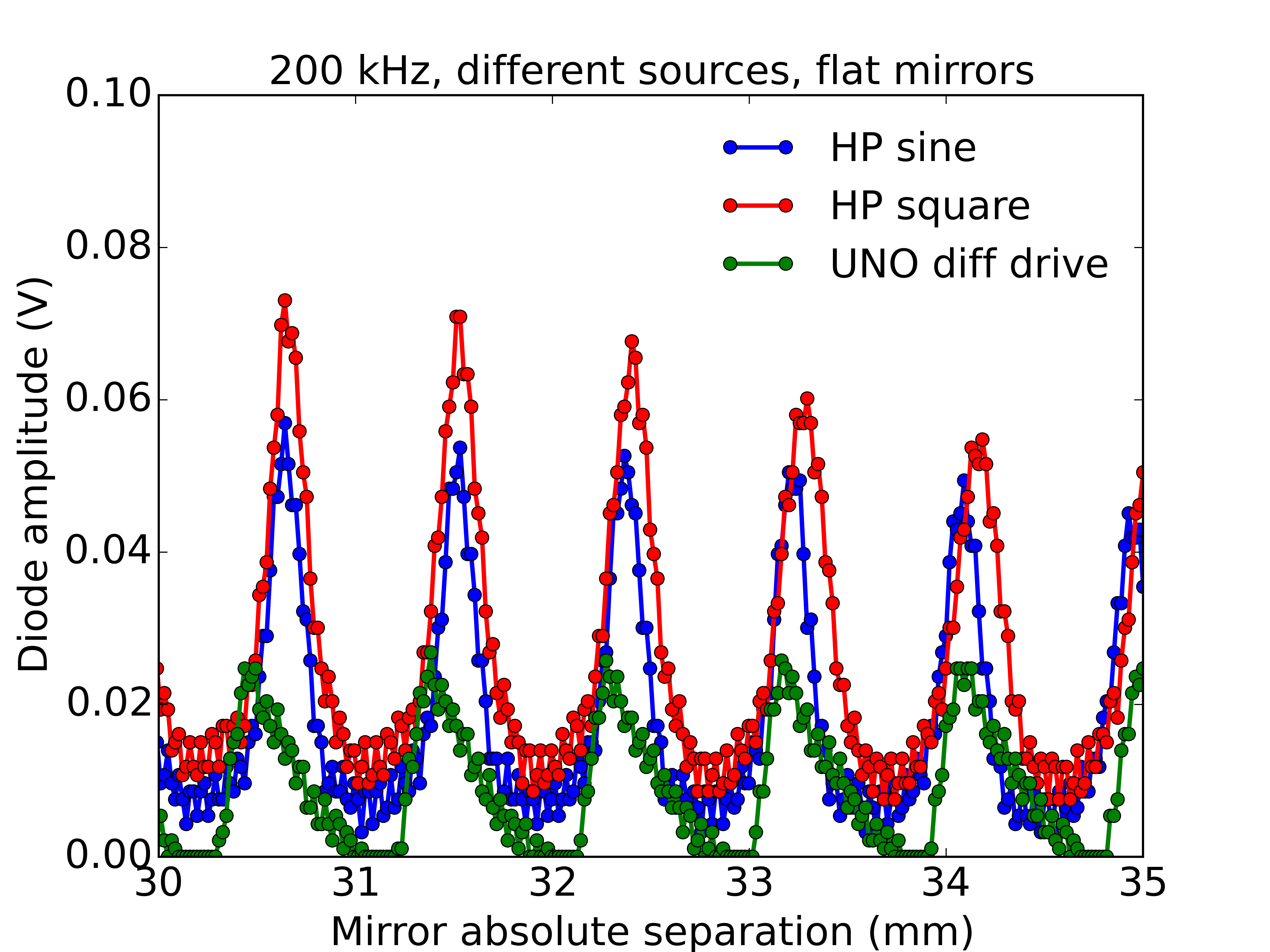
01/16/2016 at 23:12 • 0 commentsI'd been noticing an asymmetric lineshape on the interference maxima at 40 kHz and it became particularly obvious at 200 kHz. I suspected two possible causes, either vibration on the moving state modulating the path length or phase noise/jitter on the ultrasound transmitter drive. I used a old but good quality HP function generator from my work lab to help me pin-point the cause.
The graph shows a zoom-in for scans at 200 kHz with different sources driving the transmitter. I used the HP source to drive with either a sinusoid or a square wave. And I used the timer generated square wave on the UNO for comparison. I was surprised to find such a big difference between the UNO and HP data. The HP data is clearly much more as one would expect for a Fabry-Perot, showing that the spectral purity of the UNO timer generated signal (at least as it is used now) is not good enough for this application.
I was even more suprised to find a difference between the HP sinusoid and square-wave drive, with the sinusoid yielding higher Finesse. I expected that the Fourier components of the square wave would be too high in frequency to affect the narrowband transducer but perhaps this was wrong.
![]() So this gives me a challenge, to implement a digitally tunable sinusoidal drive in a compact and cheap way. One of the many options would be to use an AD9850 DDS chip. Or perhaps I can use a Si5351 clock generator and low pass filter the output. Needs some thought but it will clearly be worthwhile to use a better oscillator.
So this gives me a challenge, to implement a digitally tunable sinusoidal drive in a compact and cheap way. One of the many options would be to use an AD9850 DDS chip. Or perhaps I can use a Si5351 clock generator and low pass filter the output. Needs some thought but it will clearly be worthwhile to use a better oscillator. -
Up in frequency
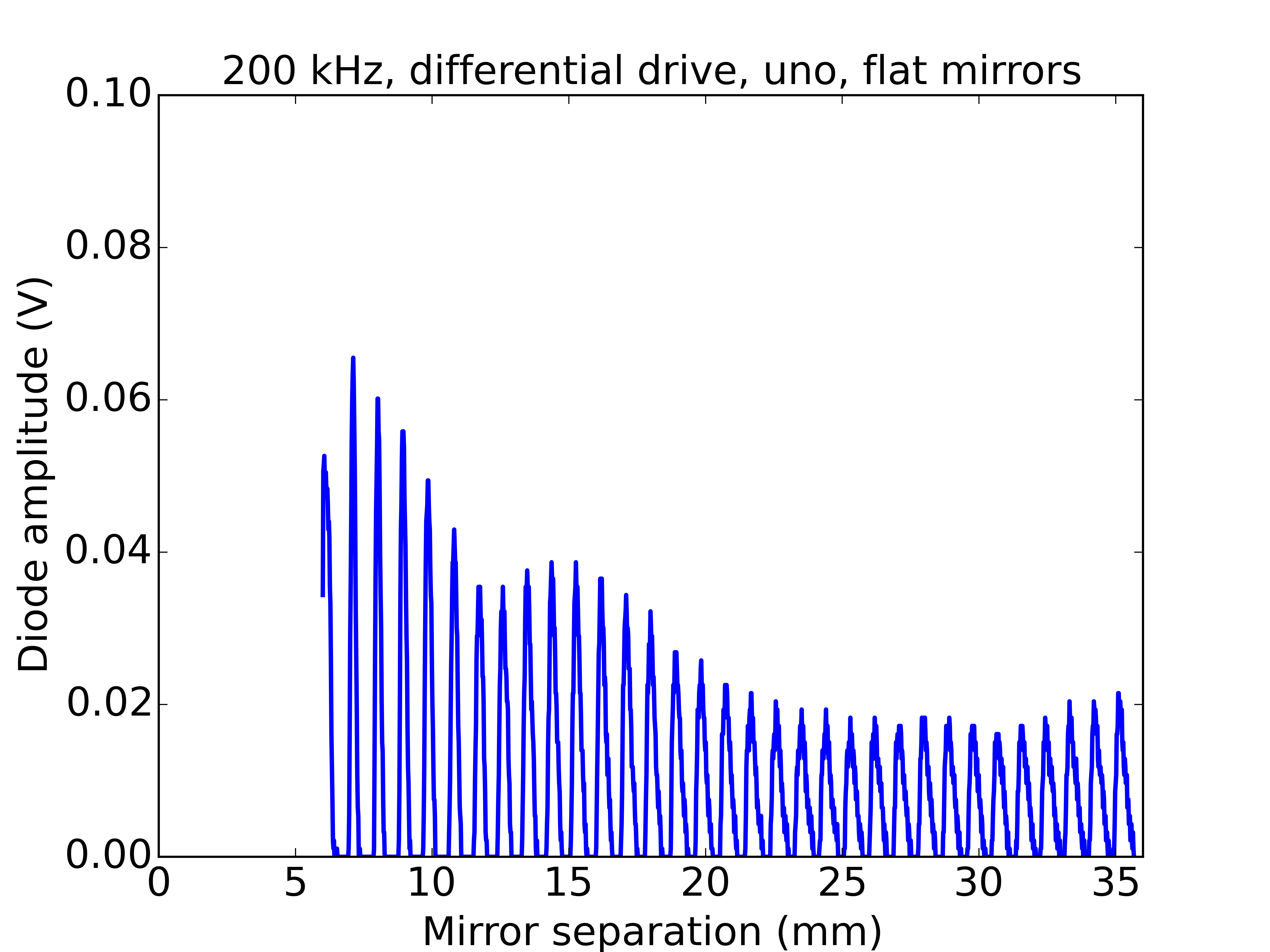
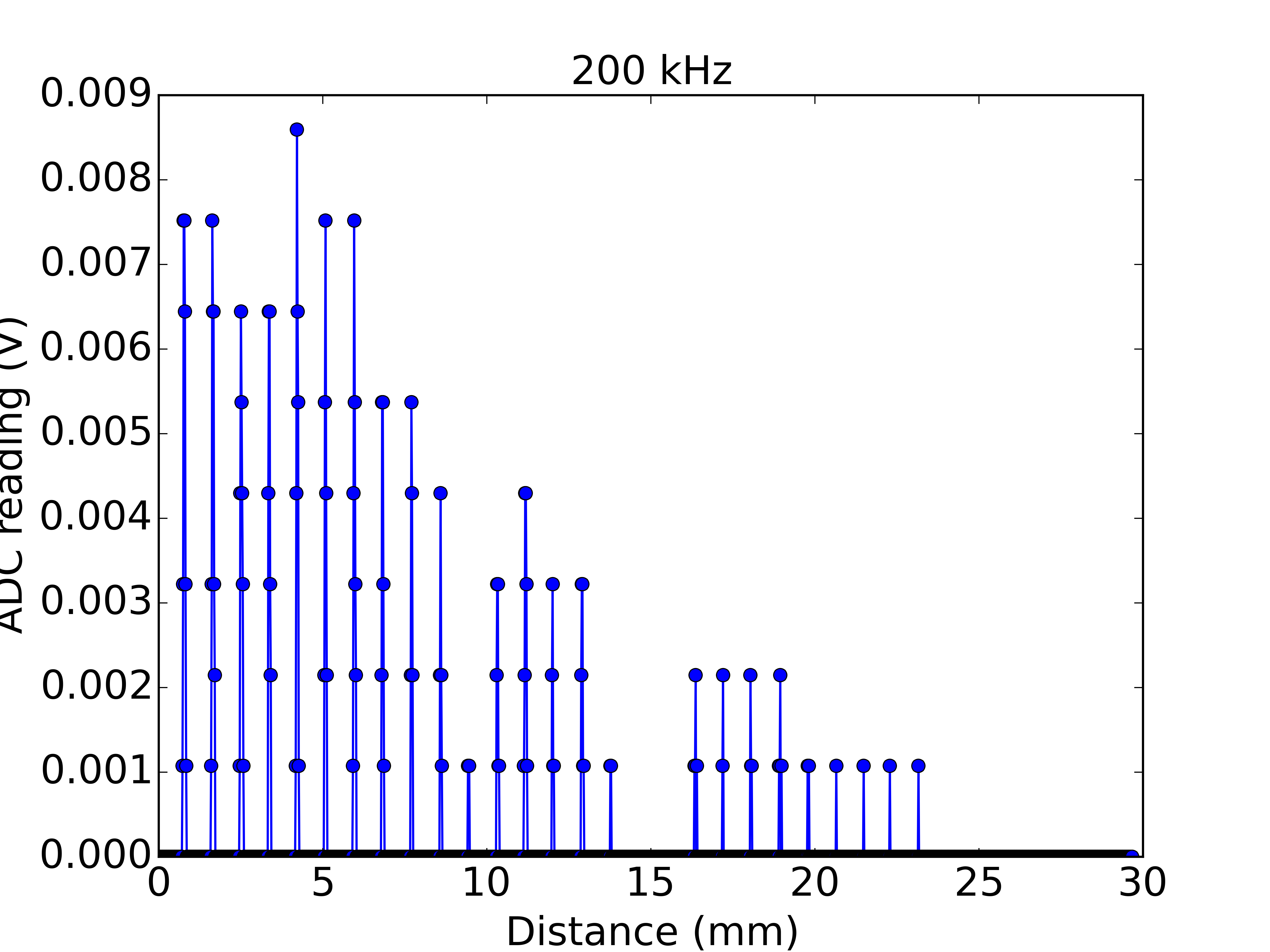
01/14/2016 at 21:51 • 0 commentsI was keen to see more fringes, mainly because it will help with future measurements e.g. of the speed of sound. Optical Fabry-Perots may operate at about the 100,000 order, and therein lies their strength as spectroscopy tools, but with 40 kHz ultrasound I was stuck at about the 5th order! So I took the plunge and bought some transducers that would push up my ultrasound frequency. I found some 200 kHz transceiver units at reasonable cost and installed them in the setup, starting with planar mirrors.
Here is one of the first datasets, showing more than 30 fringes over the travel range:
![]()
For a number of reasons the signal has gone dropped to 10's of mV, so one of my next steps will be to build a small amplifier for the receiver. Otherwise, I am pretty happy with the upgrade. Once I have more signal, it will be possible to push the Finesse up, if desired.
-
Mechanical improvements
01/04/2016 at 21:35 • 2 commentsI wanted to improve on first build of the interferometer, the reason being that the stage lacked mechanical integrity. It slightly wobbled and showed stick-slip behaviour when driven. The main reason for this, as you can see in the photo of the first build (below), was that I only used two ball-bushings, and this allowed the stage to rock and yaw. A secondary reason was that the leadscrew drive was off the stage axis, meaning that a different couple was applied to each bushing during motion. The off-axis drive can be fine, as long as the bushings fit the rails perfectly (it is used in the optical drive) but I was worried about it.
![]()
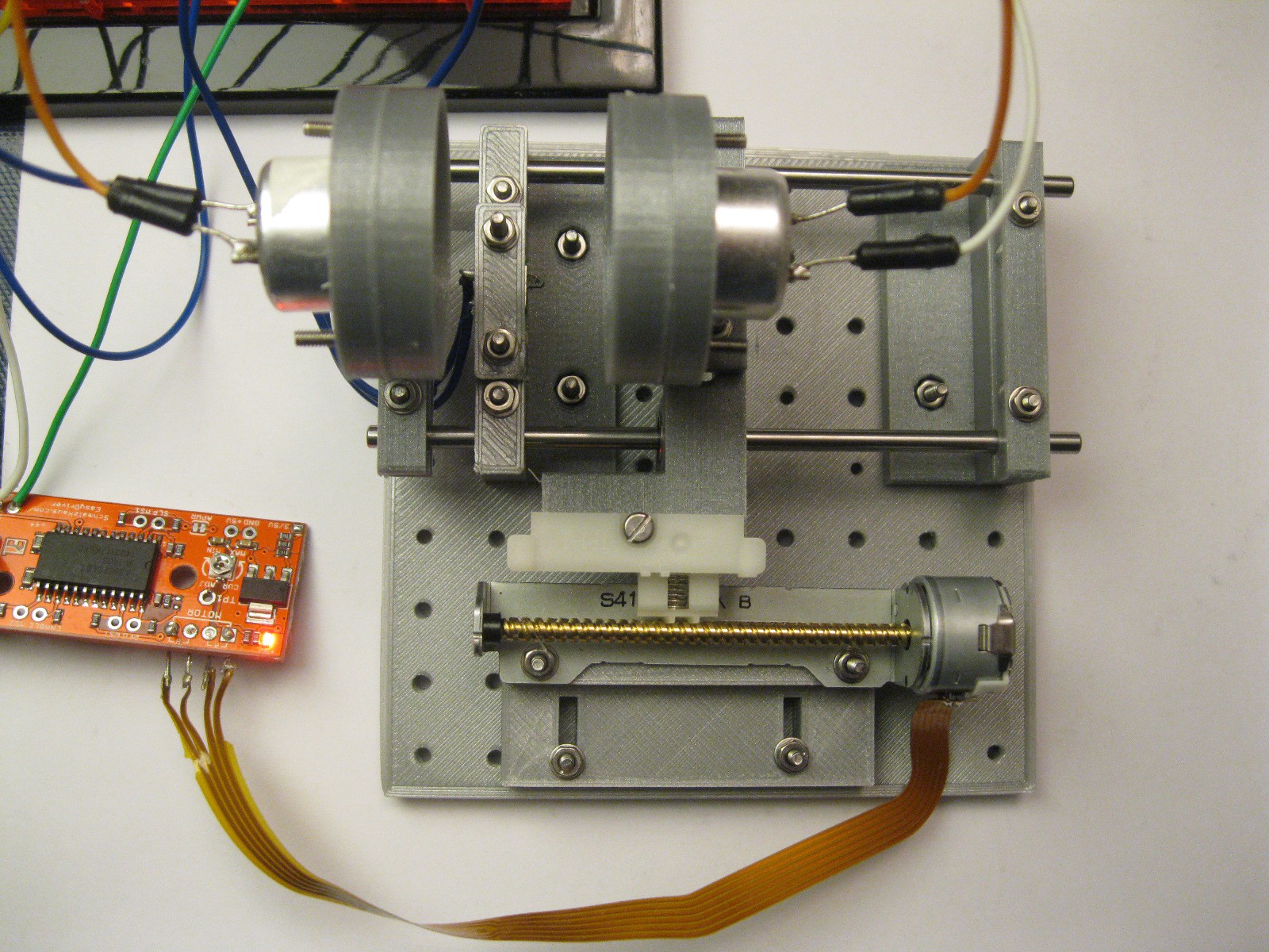
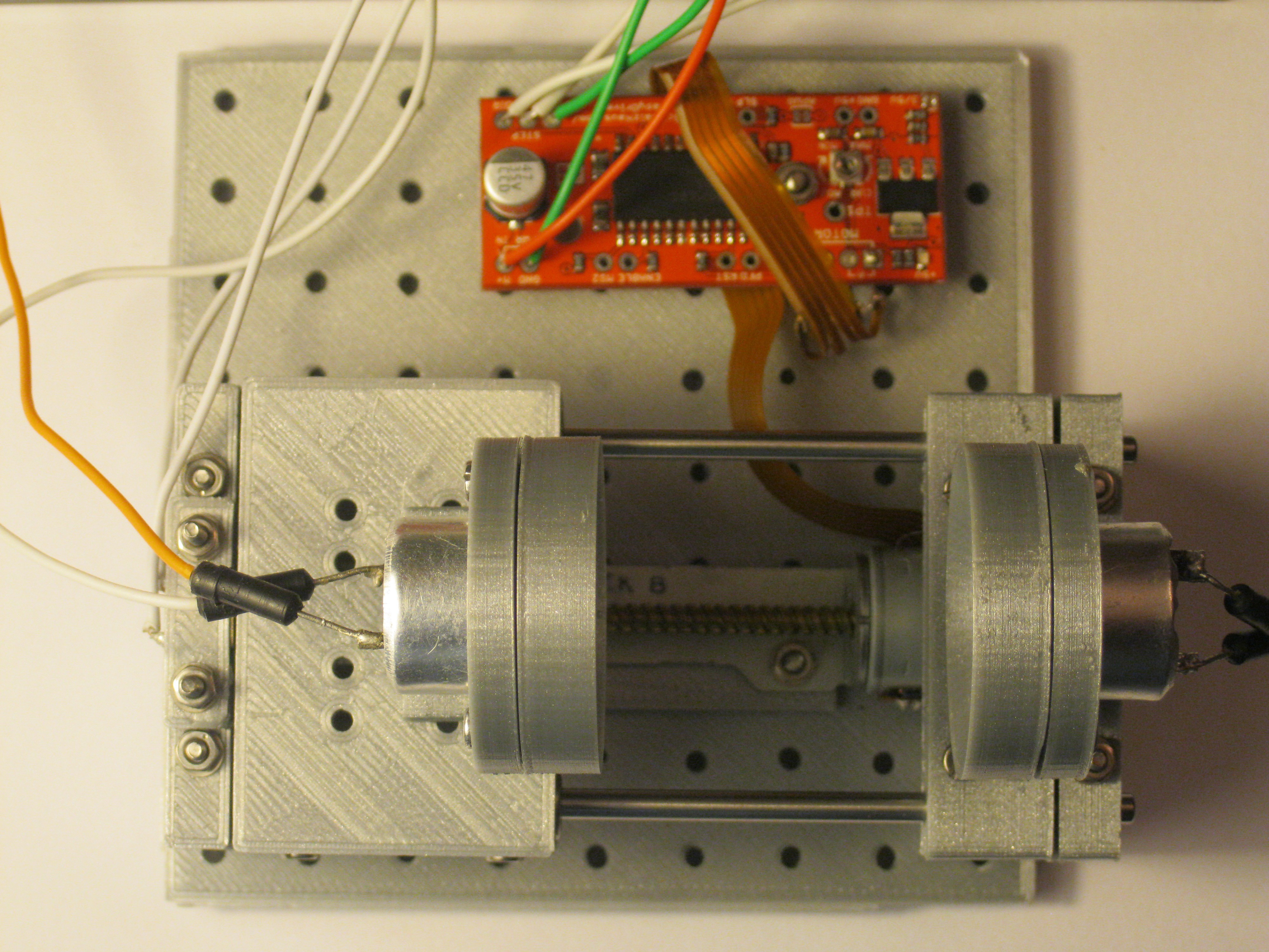
So in the second build (shown below) I have used four bushings on a larger stage and moved the leadscrew to the axis of the stage. The stage now shows vastly less wobble and there is no obvious stick-slip behaviour. In the future I'd like to quantify the stage's performance in terms of precision and repeatability. But for now I am happy to note there are no unwanted jumps in the data, as occurred previously.
![]()
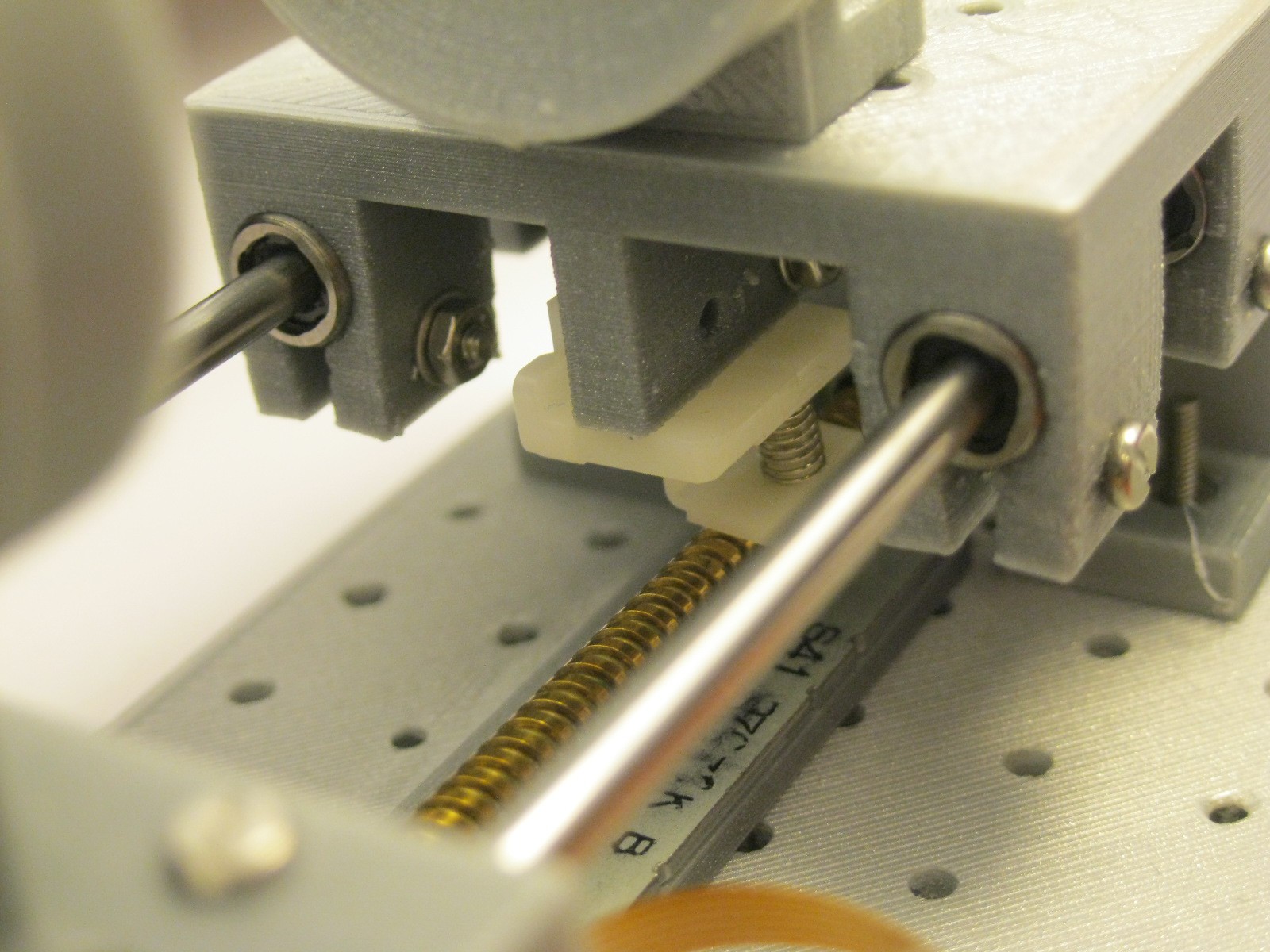
Here is a zoom in of the stage itself.
![]()
Standing waves of sound
An ultrasonic interferometer is assembled from optical drive components, 3d-printed parts and an ultrasonic range-finder.
 So, here is a time trace of the input to the amp (from the ultrasound transducer) as well as the amp's output. It has gain! In fact, the voltage gain is 47, so the simple calculations turned out to be not too bad. And, the output signal is of about the right amplitude. I am delighted, this amp is just what is needed.
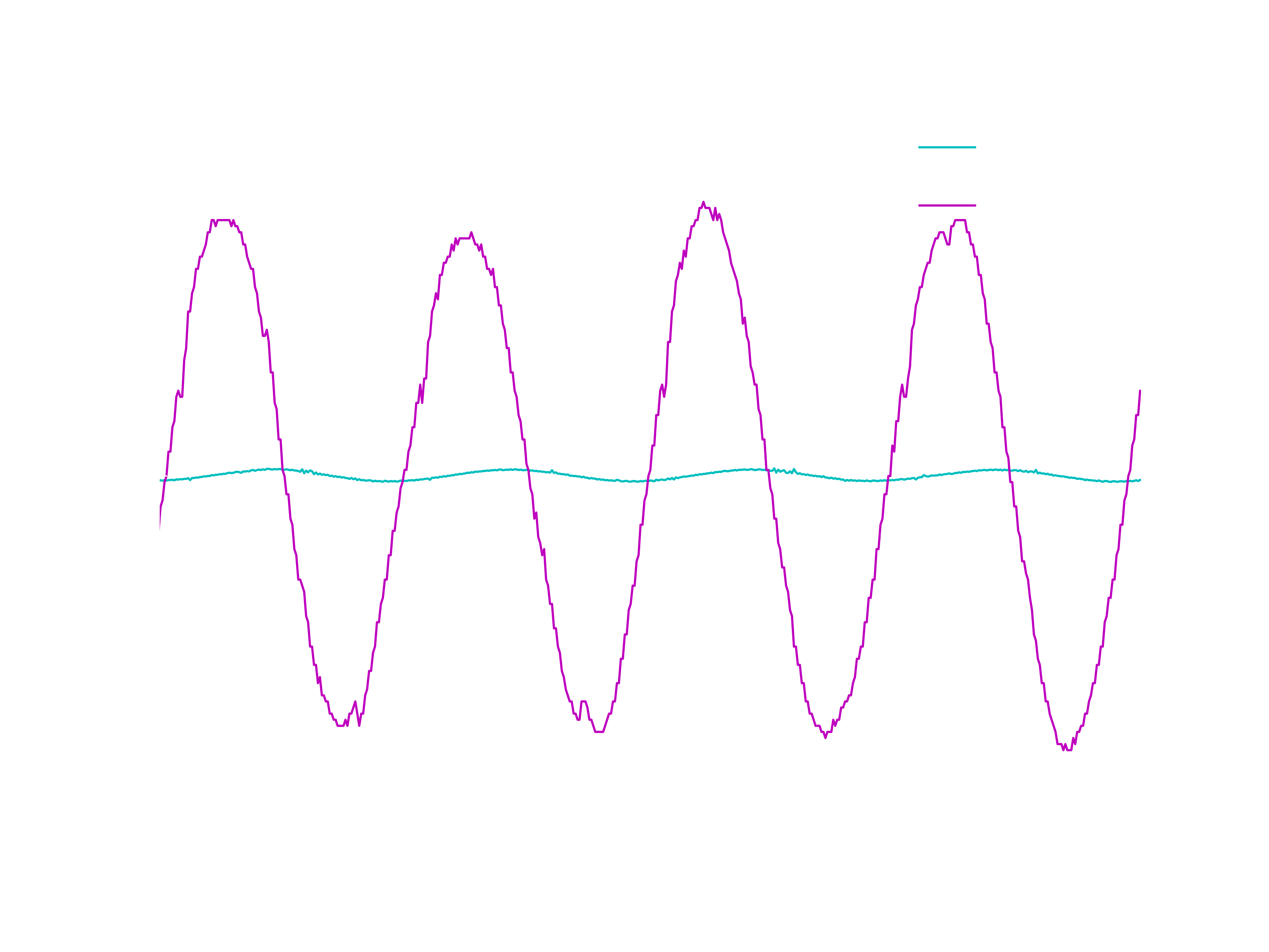


 So this gives me a challenge, to implement a digitally tunable sinusoidal drive in a compact and cheap way. One of the many options would be to use an