Alex Martin
-
Completed PCB
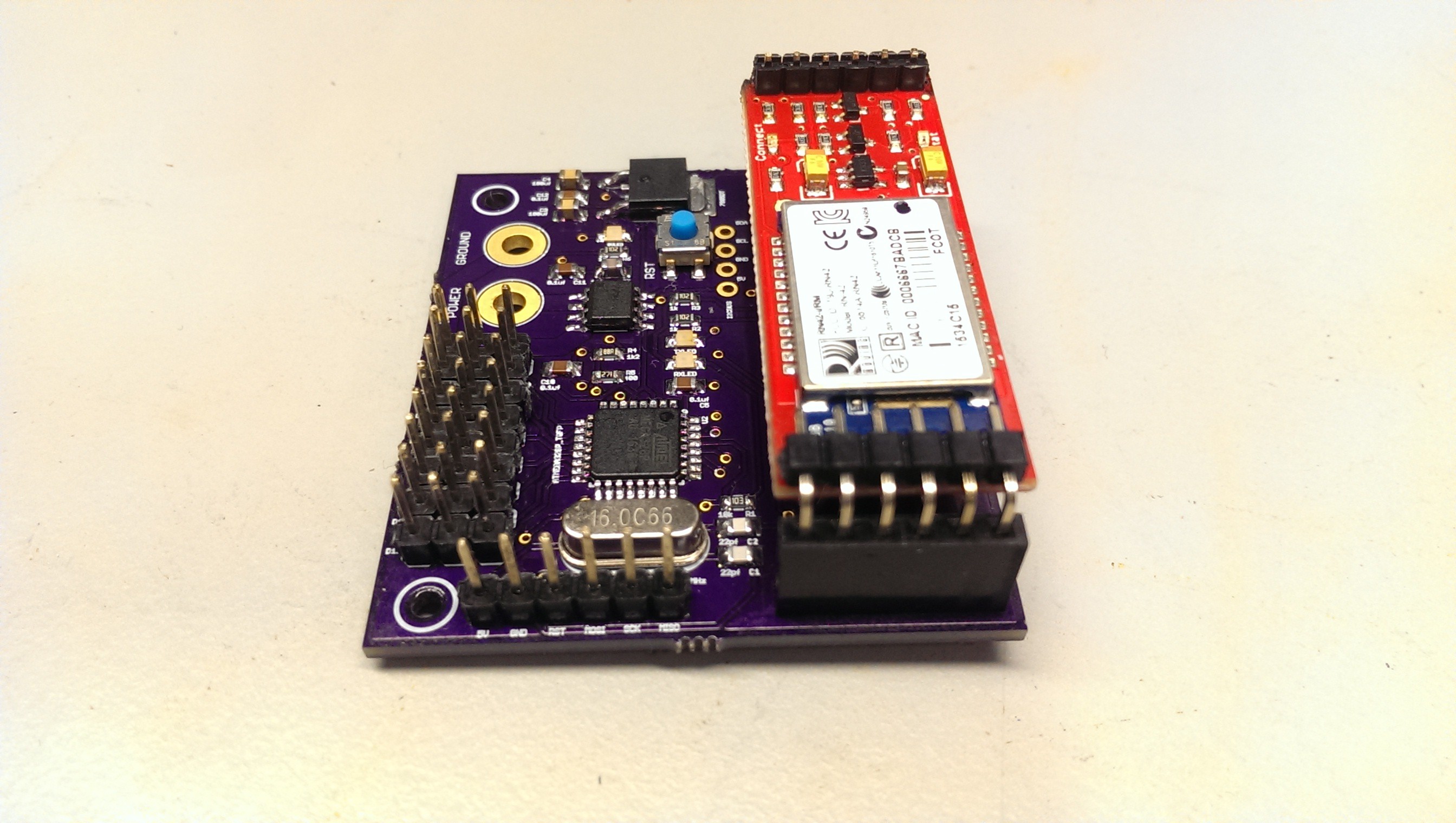
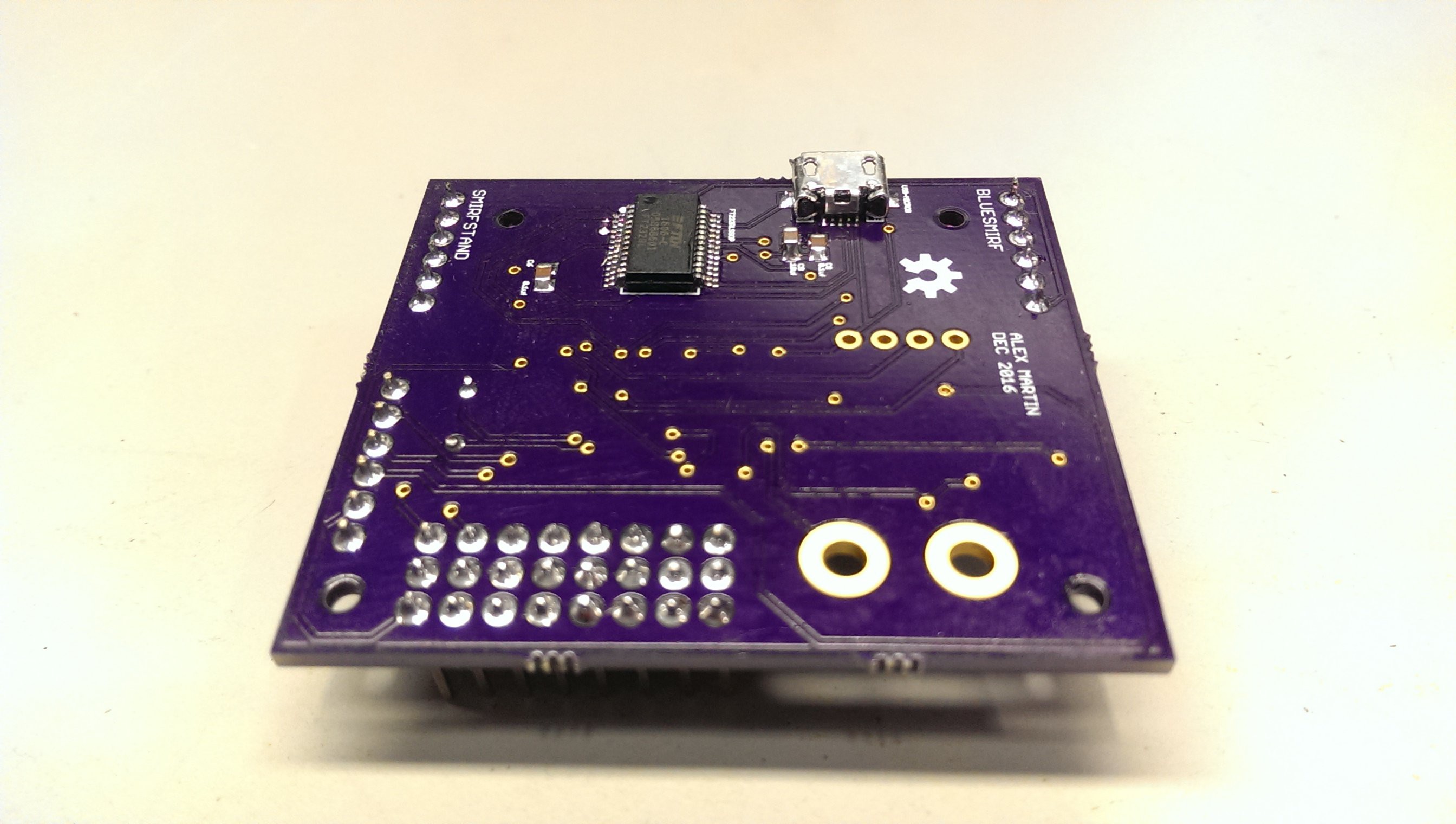
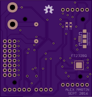
07/24/2017 at 01:26 • 0 commentsThis is an improved version of the board discussed in a previous log. The main difference is that this one works.
Changes include the removal of QFN packages, better spacing, and proper trace routing.
The primary area for improvement here is to integrate the bluetooth module into the main board.
![]()
![]()
-
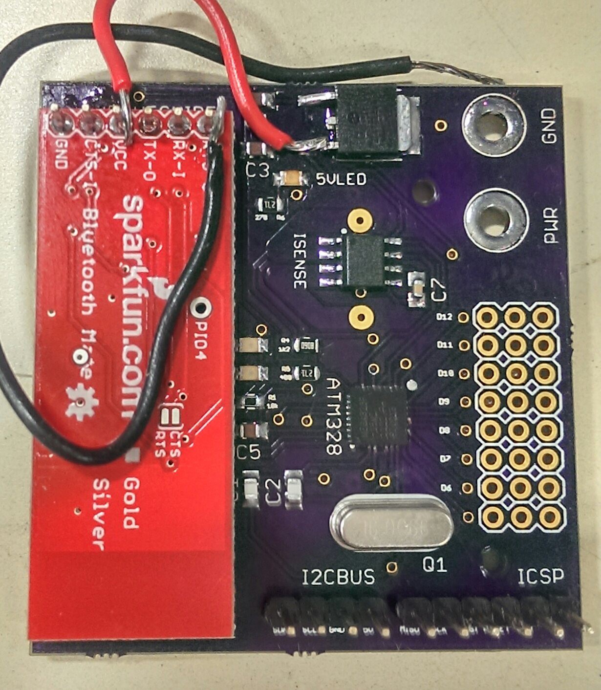
QFNs may have been a bad idea...
10/30/2016 at 01:14 • 2 commentsI put the board together a couple of weeks ago, but have been unable to get it to work properly. I successfully installed the Arduino bootloader on the ATMega, but can't load sketches onto it. From what I can tell it's because the the reset pin is not being held at 5V (for reasons I don't understand). This is confusing as the master Arduino uses the reset pin of the slave Arduino to upload the bootloader.
The FTDI chip also doesn't work. It's hard to debug as I didn't create any test points on the board. It doesn't show up in the /dev directory, and using the FTDI utility doesn't lead me anywhere.
I'm going to leave this board as is for now and keep the failures in mind for the next revision. I will be using QFPs instead of QFNs in case bad solder connections were the cause of the failures (I have re-soldered both chips multiple times, each time inspecting with a microscope). I will also be adding test points to the FTDI chip to help with debugging.
Below are pictures of the soldered board (yes, those are bodge wires). At least it was fun to put together!
![]()
![]()
-
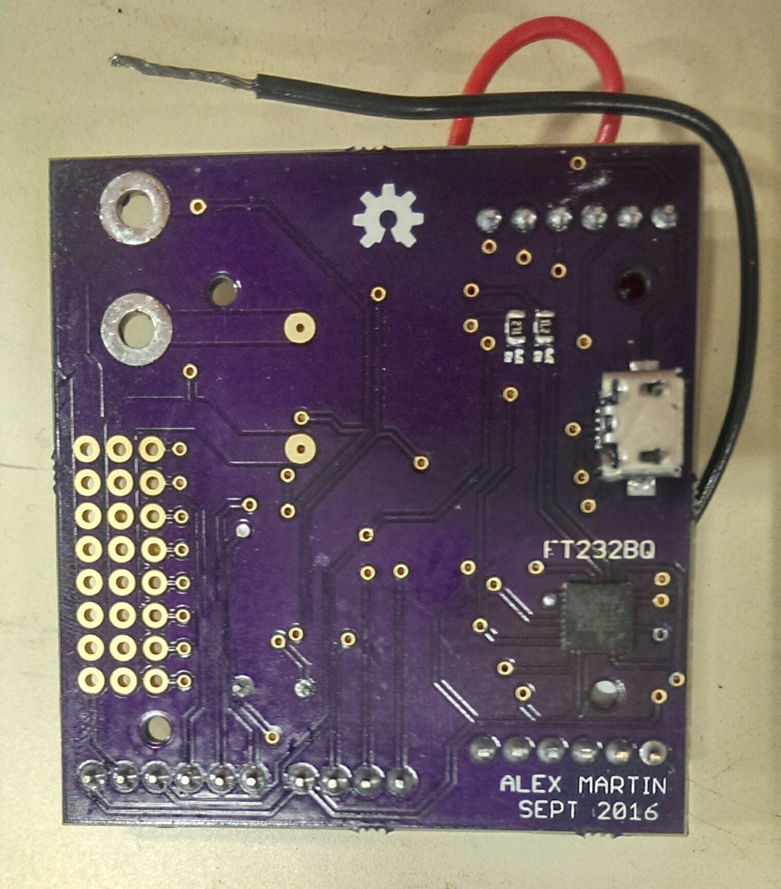
It's all coming together...
09/08/2016 at 01:52 • 1 commentJust submitted an order to @oshpark!
![]()
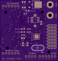
This board is based off the incredible Botboarduino by Lynxmotion (http://www.lynxmotion.com/c-153-botboarduino.aspx). It has some features removed (speaker, some IO etc), and some features added. The new additions are:
- Current sensing (ACS715)
- Bluetooth (BlueSMIRF)
- Juicier battery traces with ring terminal connectors
![]()
![]()
The premise of the design was to keep the components as tight as possible (hence mostly surface mount), have the servo connectors / power connectors on the same side, and the USB connector opposite to the servos / power. This board will be mounted in the rear body of the robot (not much space!) so it needs to be concise and well organized.
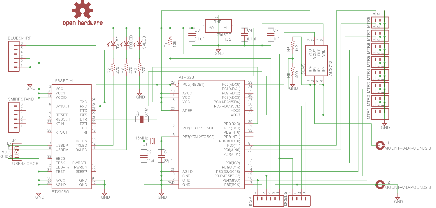
Schematic:
![]()
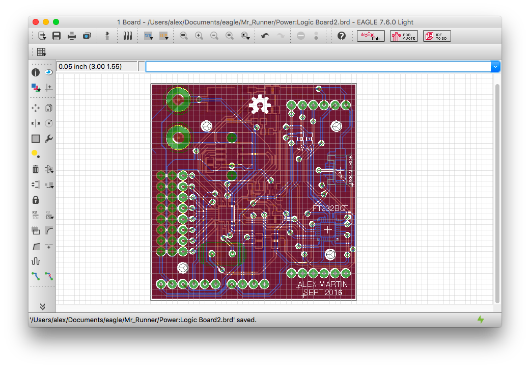
Board view:
![]()
I got lucky and the design was sent off the fab immediately after it was submitted, so the boards should be here in around a week. Alright!
-
New updates coming soon!
09/03/2016 at 17:41 • 2 commentsPCB, design, videos, etc.