Nick Sayer
-
Supply chain issues
12/08/2021 at 22:44 • 0 commentsUnfortunately, the AP63205WU (the buck converter to go from +12 to +5V) is out of stock everywhere and it appears like it won't be back in stock during 2022. Go figure.
I use this chip in a lot of things, it turns out, so I'm screwed.
In some cases, I can substitute an AP1509, but it's a SOIC-8 instead of a SOT23-6 and does not include a synchronous rectifier, so it means adding a Schottky diode to the circuit. There just isn't room for all of that on OpenEVSE II.
I'll post back when the 63205 becomes available again. But for now... I'm out.
-
Latest updates
08/08/2021 at 19:37 • 0 commentsThe primary supply is now 12 volts because when you use a 12 volt relay that winds up being where the load is greatest. Therefore, using a buck converter to make the 5 volts for the rest of the system makes more sense than trying to boost 5 volts to power the relay. That does mean that the voltmeter winds up being powered by the buck converter on the display/logic board, but that seems to be ok.
The switching part for the 12 volt relay is now a self-contained protected MOSFET designed specifically to drive inductive loads like relays. It includes self-protection against coil collapse voltages and short circuits. It's also in a beefier package.
-
Combined HV board
03/19/2020 at 08:01 • 0 commentsI don't know why it took me so long to figure this out, but there's no real reason to have more than one HV board layout. You can simply stuff the SSR based components for a contactor or the MOSFET parts for the DC relay and leave the unused side unfinished.
I've also decided to go with a 10W AC-DC module, as the HV board is shared between this project and the Pi EVSE Hat, and in that version of the project it's also necessary to power a Raspberry Pi with the 5v power output. Powering a Raspberry Pi and a 12 VDC relay is probably asking too much of a 5W power supply.
I've got this design into OSHPark and will report on whether it's a win or not when those boards get back.
-
Voltmeter success
12/23/2019 at 07:45 • 0 commentsOne thing I discovered trying to troubleshoot the new design for the voltmeter was that the secondary side was wired backwards. I lifted the two pins and swapped them with wires, but it still didn't work. It's possible that the period of time it was in circuit miswired was enough to blow the phototransistor. Not sure.
I ordered two new boards from OSHPark for testing. One with the same circuit (but with the mistake fixed) and the other with the other type of circuit from the IXYS application note. I would much prefer the Photovoltaic variant rather than the Photoconductive because the former has much better linearity and accuracy at the cost of reduced bandwidth (but bandwidth here doesn't matter).
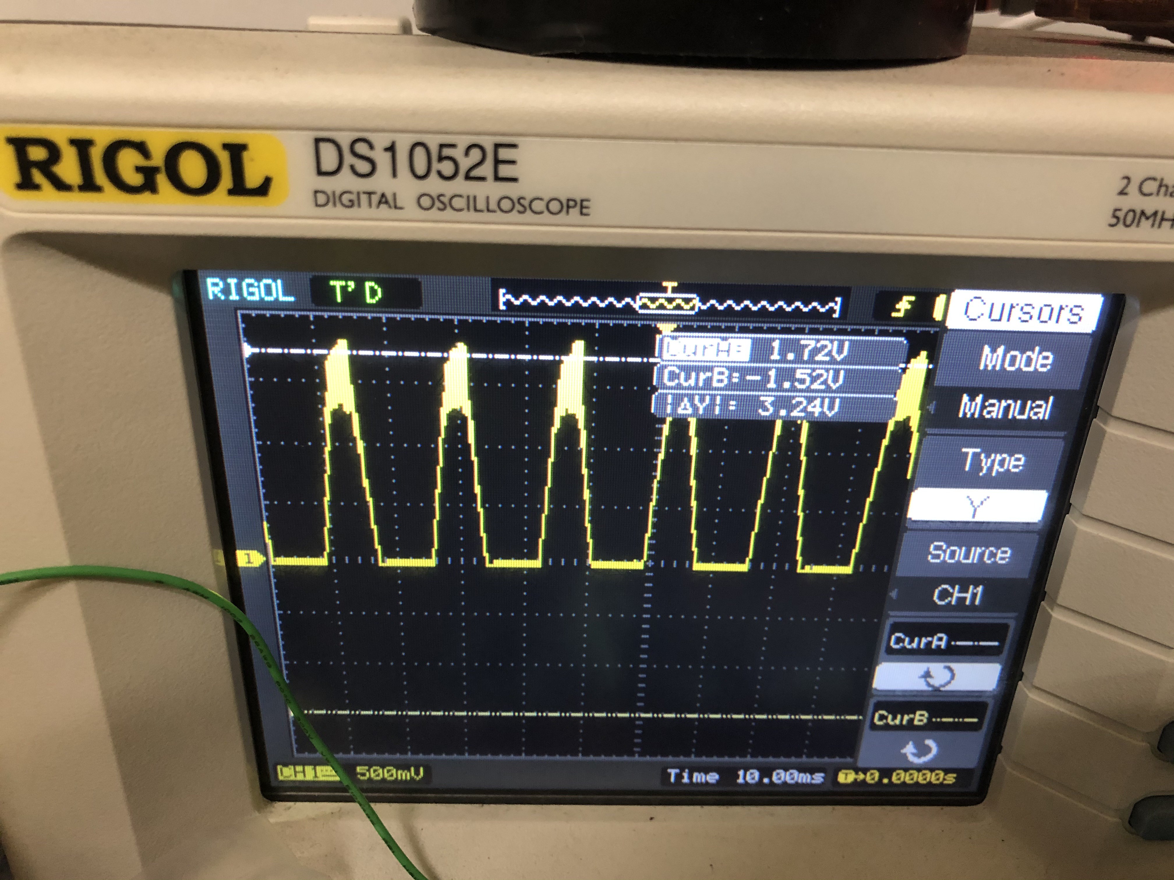
Turns out both work, so I'm going with the photovoltaic variant. When powered with 120VAC, the output on the scope looks like this:
![]()
That's a little noisy, but the peaks look consistent enough that merely getting a peak reading and scaling the result to infer the RMS voltage should work just fine.
The design starts with an isolated 5V DC-DC converter. This is powered on the primary side by the 5v supply that powers the whole system. The secondary side has the negative pole tied to the neutral AC input (for L2 systems, this won't actually be neutral, but that doesn't matter. For our purposes here, it'll be regarded as the circuit ground). The hot AC input goes through an S1M diode to isolate just the positive going half-cycle. That then feeds into a voltage divider made with a 510kΩ flame-proof resistor and a 6.8kΩ one. The values chosen insure that the current through the divider results in less than 1/8W, and a nominal output of about 4.5V for a peak DC input voltage of 340V (which is the peak for 240 VAC RMS).
The output of the voltage divider feeds the input to the isolator circuit. The input and output impedance resistors are set to 75kΩ, as the arithmetic says this should result in a peak LED current of around 15 mA or so. The transfer current through the primary side phototransistor provides feedback to the input amp which sets the LED current. The secondary side phototransistor sends the same current to the output buffer. Because the whole idea is that the two phototransistors are very closely matched, the output should very closely mirror the input regardless of any non-linearities in either the LED or the phototransistors (this includes any temperature related effects).
-
Voltmeter revamp
09/03/2019 at 17:51 • 0 commentsThe voltmeter is the remaining sore spot in this project. It's not very accurate, and it's got a relatively large temperature coefficient. It's bad enough that it effectively makes the watt-hour logging useless.
The non-linearity and temperature sensitivity is the fault of the optocoupler. The fix is to use a precision linear optocoupler. These have two photodiodes in the optical path, one is located on the input side, the other on the output side. The one on the input side is referred to as the "servo" photodiode and is placed in the feedback loop for the op amp that's used to pass the AC voltage across. For that, we use the existing 150 kΩ flameproof resistor along with an HV diode and a more ordinary 2.4 kΩ resistor to make a voltage divider. That should reduce 340 volts to 5 volts, giving us only one half-cycle ramping from 0 to 5 volts. That, in turn is designed to give us an LED forward current of 0-25 mA, which will be influenced by the servo current feedback. The transfer ratio (post correction) is about 0.01, so 25 mA turns into 250 µA. Across a 20 kΩ resistor, that's a 5 volt drop, so that should give us full scale on the ADC.
Of course, none of this is tested. I'm not entirely sure how I'm going to test it, really. HV makes me extremely nervous - which is why I went to such lengths to separate the HV from the logic system in the first place.
-
Power supply revamp
01/16/2019 at 18:57 • 0 commentsThere's been a bit of a revolution in how power is handled with this project. Along with the Hydra, I think we may migrate from a 12v primary AC/DC supply to 5v, and then derive the 12v with a boost converter rather than deriving the 5v with a buck converter.
Unlike the Hydra, however, 12 volts is not just used for the pilot generator, it's also used to power the relays on two of the AC board variants. The internal relay variant has two relays with 1W coils, so 2W of power is needed just for them. That means those variants need 5W supplies, but it's probably not worth stocking a 3W supply just for the contactor variant.
The good news is that the new PSK-P5B unit is footprint-compatible with the old VSK-S3 unit we were using on the contactor AC board - much smaller than the VSK-S5 unit we were using on the other two. This allows us to shrink the "external relay" AC board slightly (the "internal relay" board's size is dictated by the relays, unfortunately). In fact, I've managed to shoehorn the "external relay" board into the OpenEVSE board's original footprint. That means that that particular variant should install in the OpenEVSE chassis without any modification at all!
-
Under construction
01/10/2019 at 21:26 • 0 commentsIt's been a while since this project has had some love given to it. Recently I brought the Hydra up to date, and this project will benefit from that.
The power boards (versions 1.2) are still state-of-the-art, but the logic board has had some improvements made:
- The MC34063 -12 inverter supply has been replaced with a charge pump, which is much simpler.
- The 5 volt supply is now made from an AP1509, which, again, is much simpler
- The pilot generator now uses a pair of SOT23-6 complimentary MOSFET pairs, which is the same design now as the Hydra.
I intend to upload the new board files and add PDF schematics for all of them shortly.
The one aspect of the design that's somewhat less than satisfactory is the voltmeter. The optoisolator transfer function is very heavily influenced by temperature. In freezing temperatures I've seen L1 readings of about 140V, which is a 16% error. It is good enough to tell the difference between L1 and L2, at least.
Anyway, despite being a slightly older design, my current "portable" EVSE is an OpenEVSE II design that has been operating successfully for years. The OpenEVSE project has advanced from where this design was, and I'm not sure how many of its current features would work (likely those that are based on i2c peripherals or connections to the serial port would work ok), but I'm still proud of this design.
OpenEVSE II
A new design for OpenEVSE - the open hardware EV charging station