-
Z-axis Mod
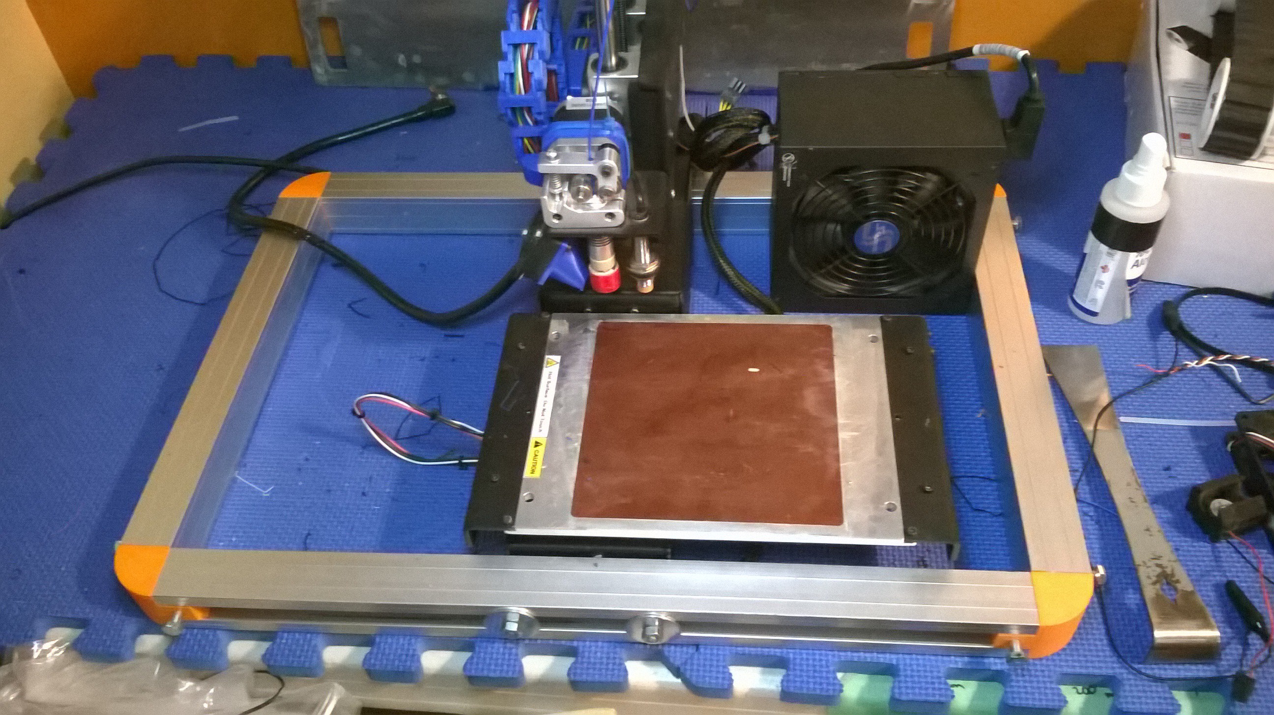
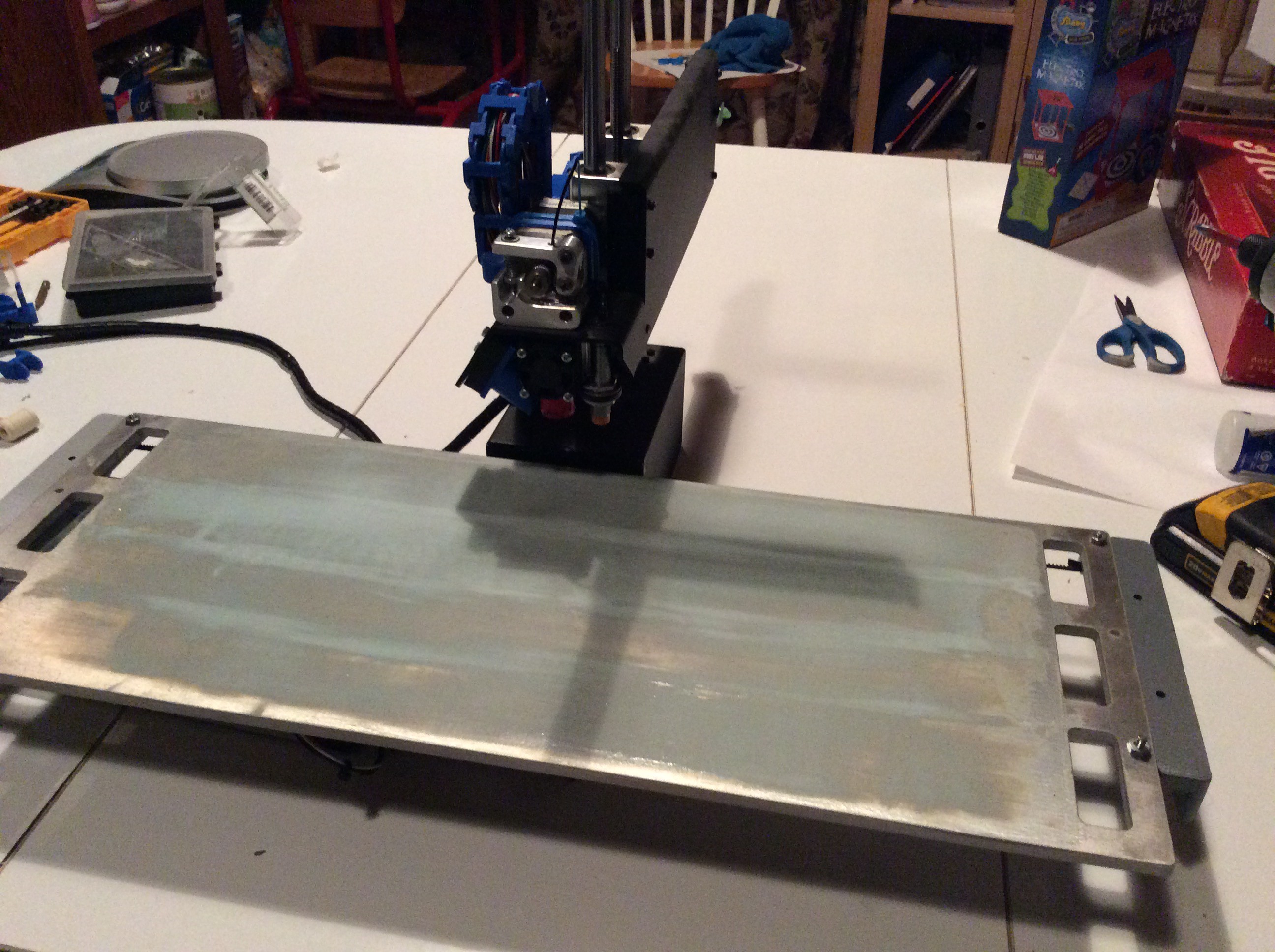
04/26/2017 at 21:03 • 0 commentsWaiting on an aluminum block to press my Z-Axis rods/rails into. The rods are a hefty 12mm diameter optical railing. I will have to mount the filament reels in another location vs the top of the Z, however convenient it was to have it there.
Printrbot has a very specific aluminum block that is used to support the Z-Rods.
Problems I may encounter are Z-sway and Z-torsion. Sway may come as a product of bed movement, even with the spiffy frame I built. Z-torsion or twisting of the Z-axis rods as a unit, can be a result of bed movement and possibly torque of the extruder motor.
-
Bearings on board...
03/29/2016 at 23:45 • 0 commentsOk... so the printing bushings didn't work out.
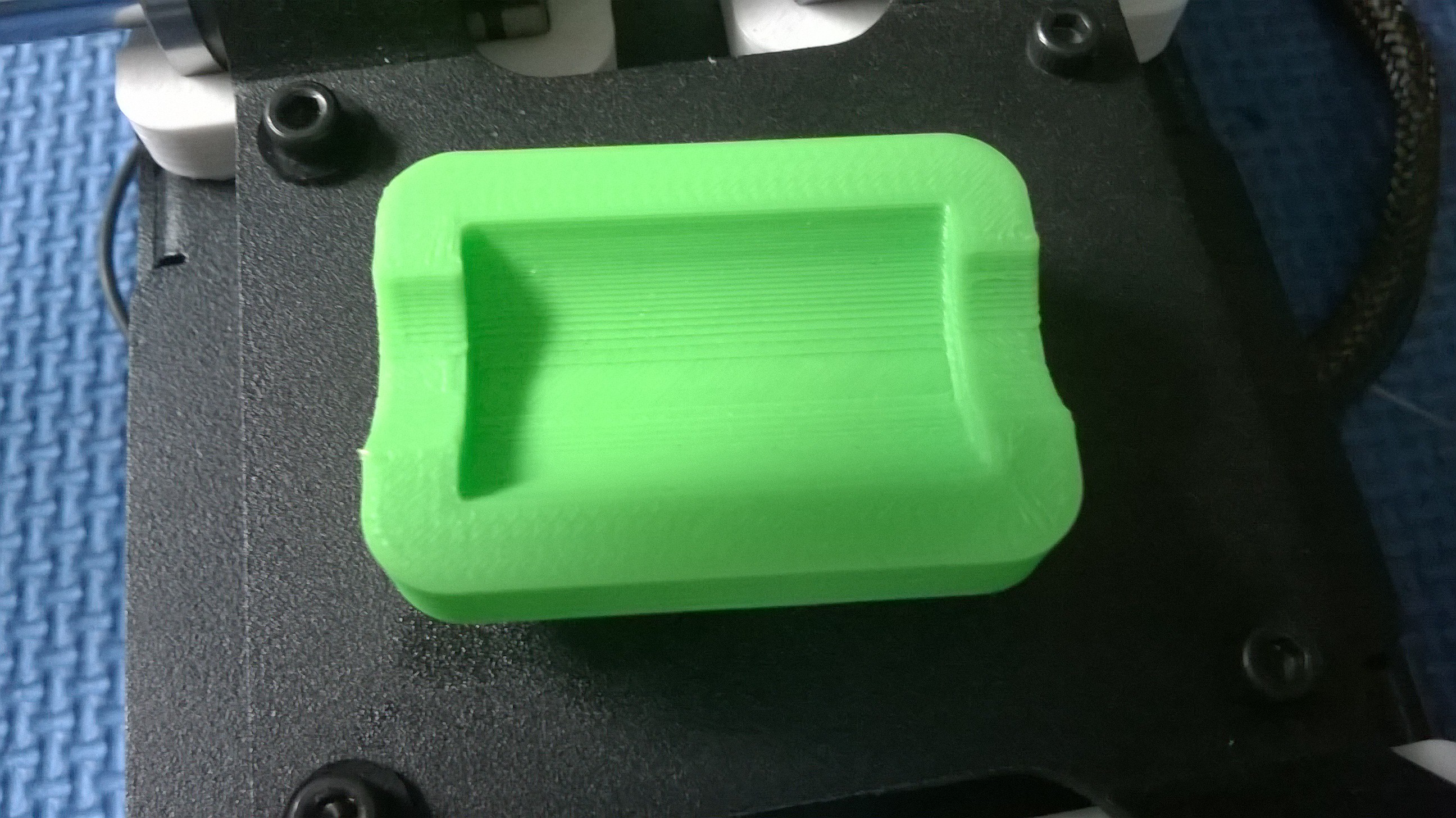
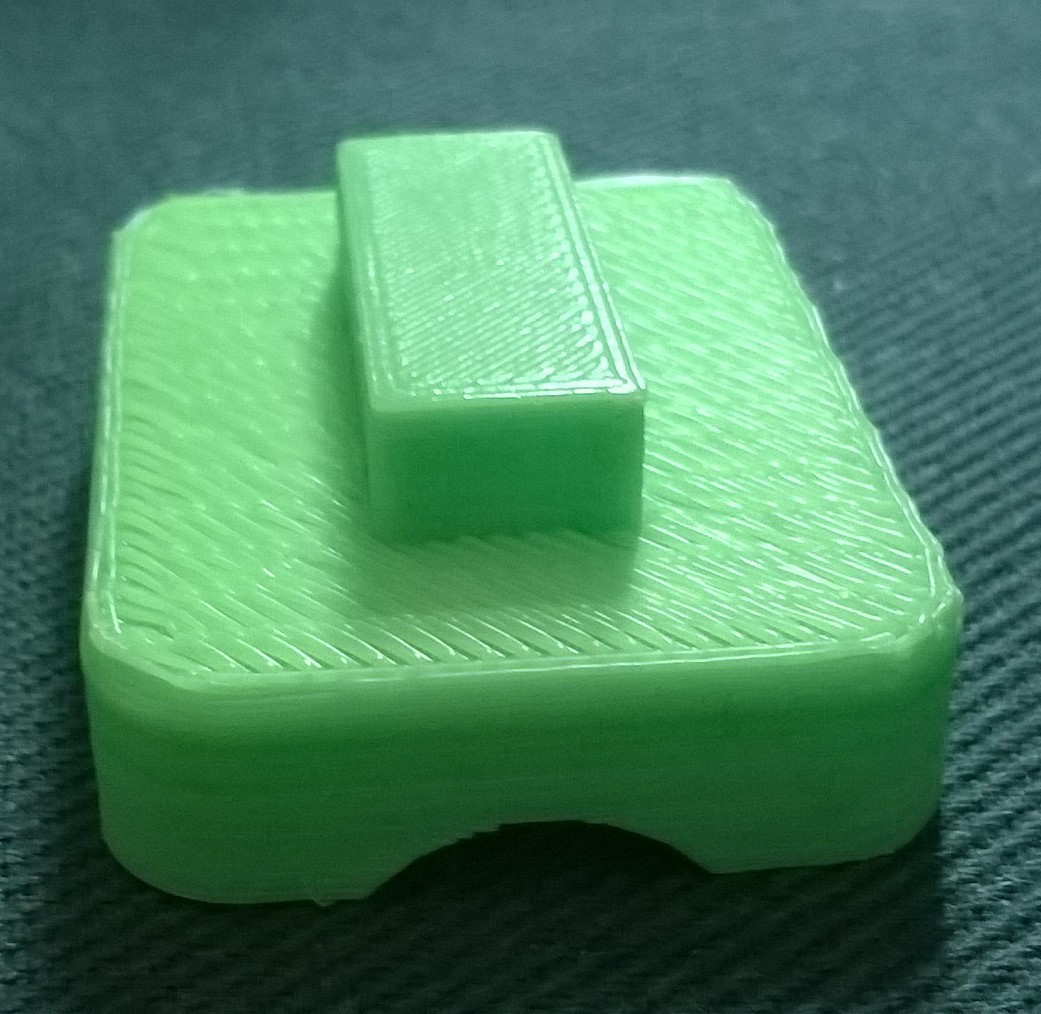
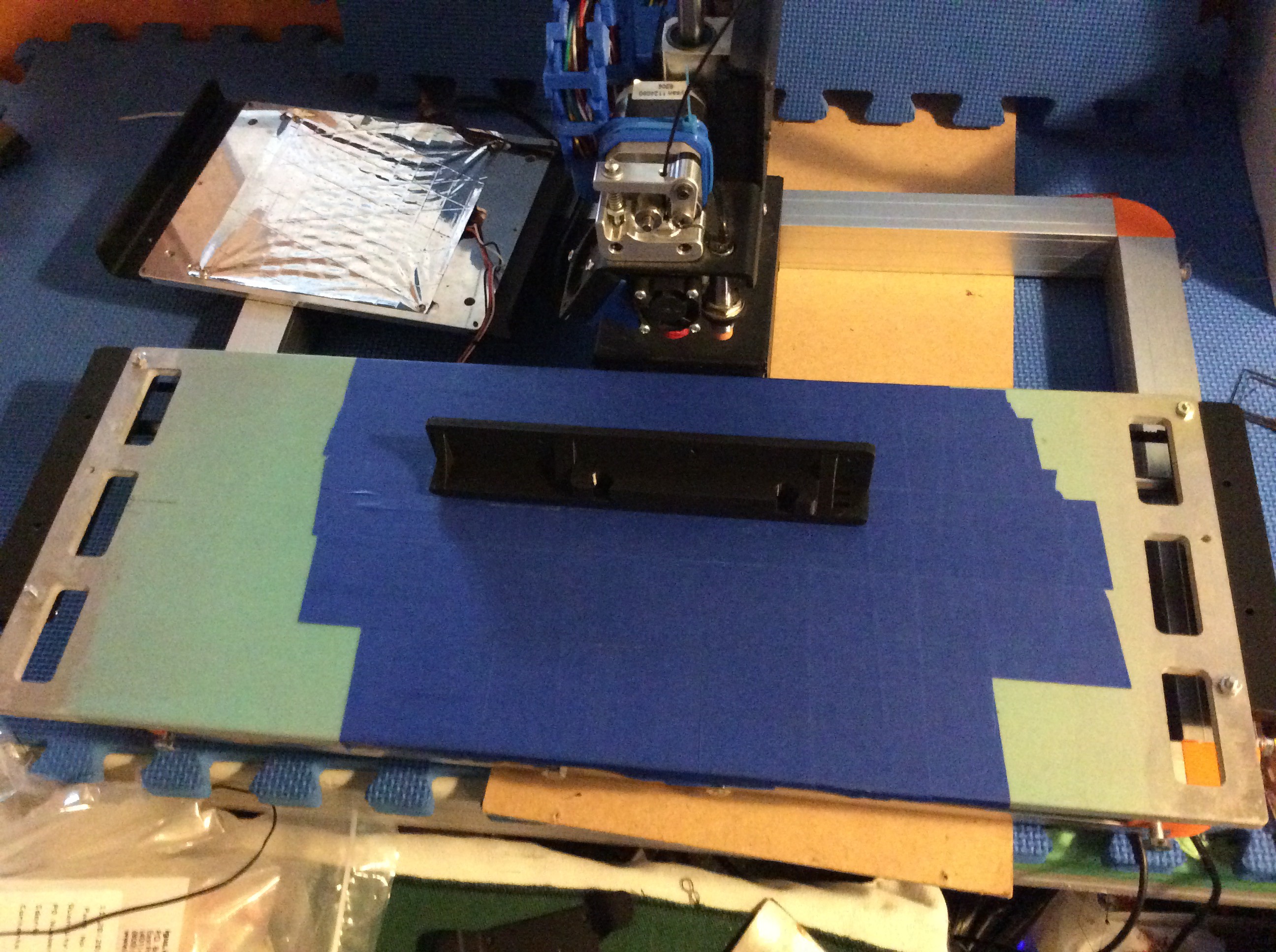
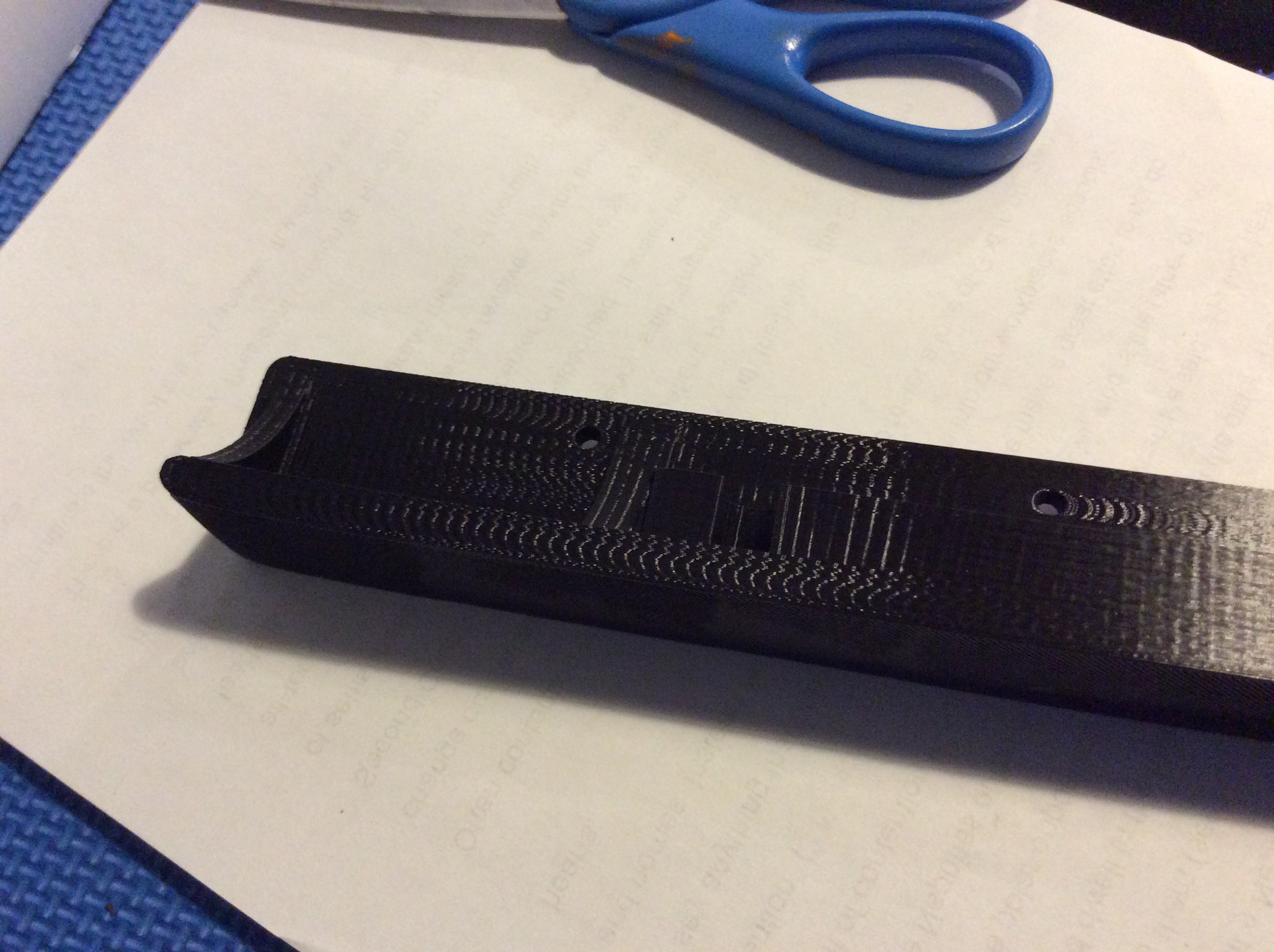
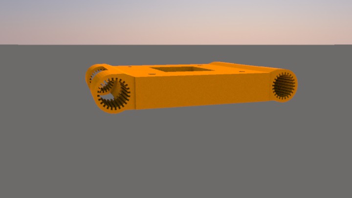
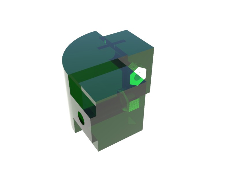
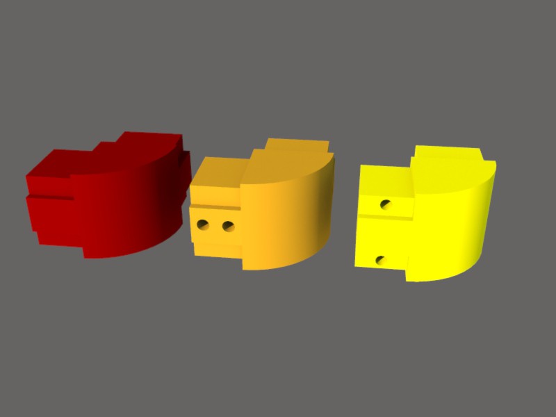
I finally got some 12mm linear bearings and tried installing them without modification. The 12mm bearings are quite a bit longer than the stock 8mm bearings, so they didn't fit in the frame holes (this was expected). I designed and printed some cradles that slot into the holes in the frame to hold the bearings in place. These are the originals:
![]()
![]()
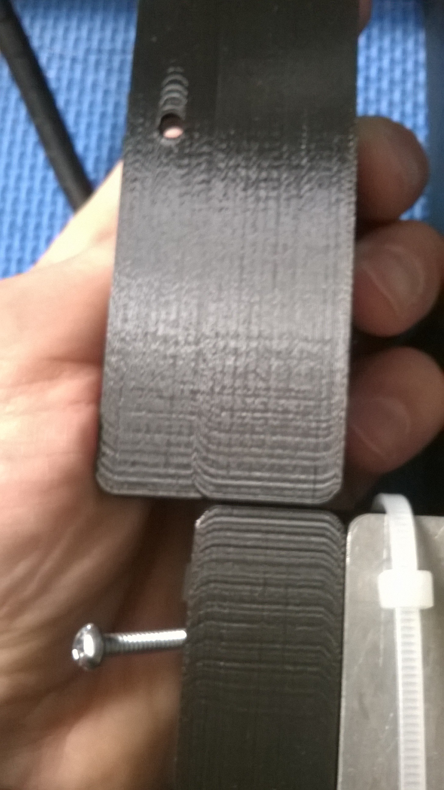
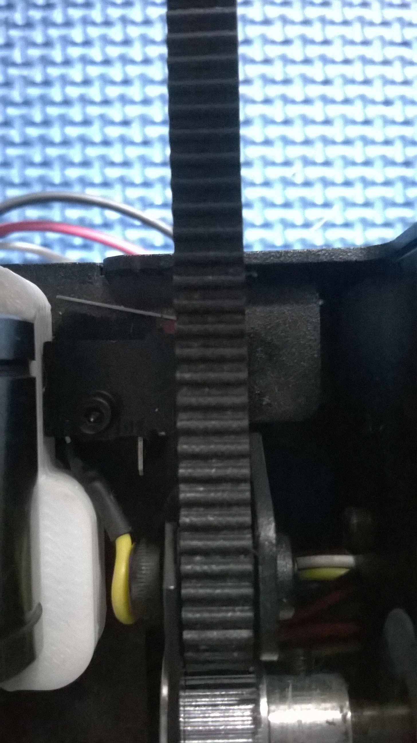
Great idea! But there were some issues. The insert bit fit too loose, one cradle interfered with the endstop switch, and the whole cradle stuck out too far. A quick redesign and reprint, and everything fits. But the end of the x-axis rails no longer connects with the endstop before it hits the bearing. I drilled a hole and put in a machine screw to hit the endstop switch and voila! Success.
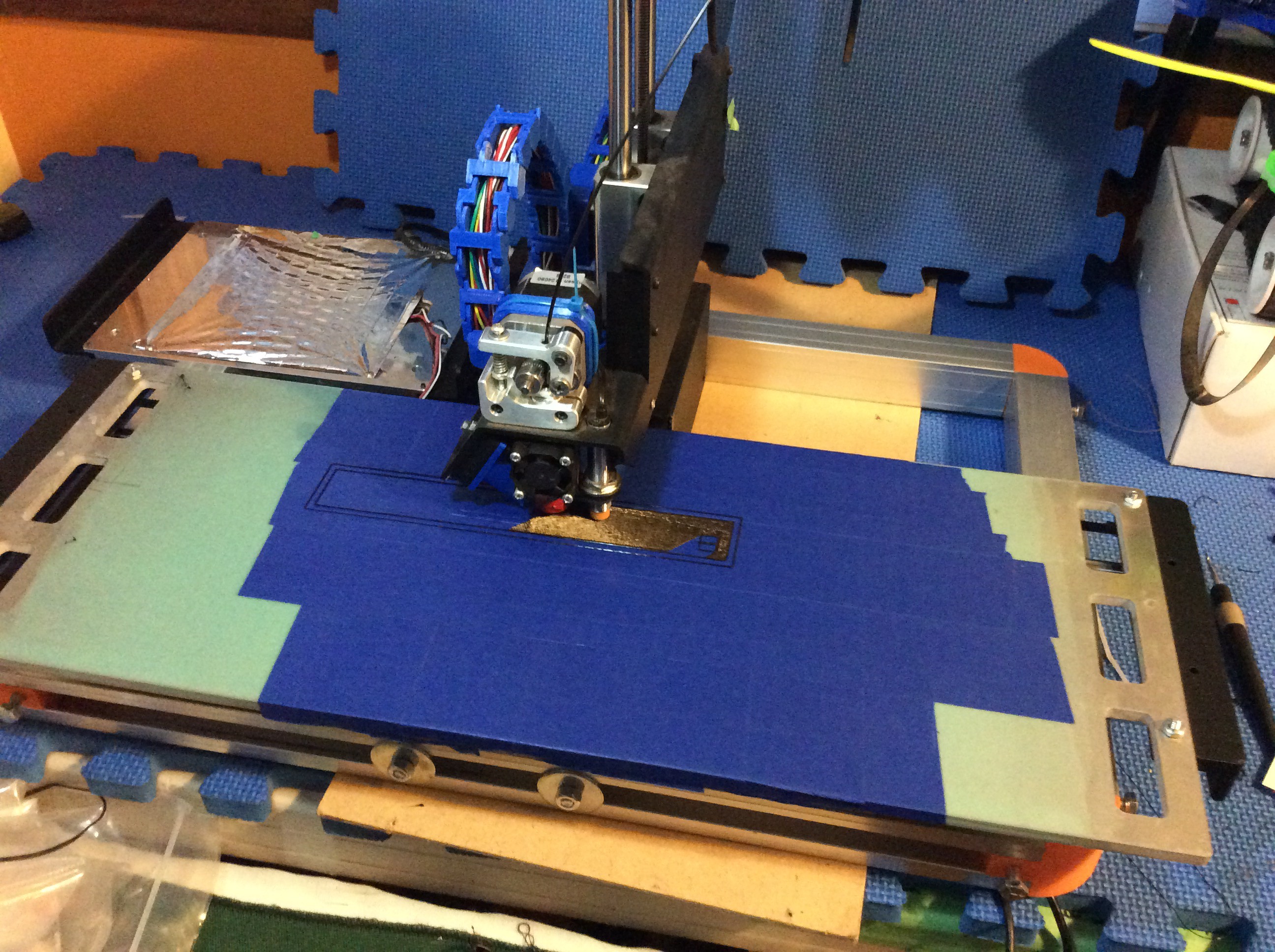
First print was the other x-axis end. Seems like I have reduced but not eliminated the jiggles... yet.
![]()
![]()
-
Shake out the jiggles!
02/13/2016 at 03:24 • 0 commentsAlthough the printed bushing block was a good idea and may be functional with a bit of scaling, the wiggles have made me reconsider. After inspection, I found that the diameter of the bushings had increased just slightly, but enough to allow play. I may try to print out the actual bushing part with igus tribo-filament and somehow marry them to a PLA block. Meanwhile, I am swapped out to the measly 150mm again... However, the frame looks nice and the whole thing is super stable!!
![]()
-
First print!
02/05/2016 at 20:14 • 0 commentsFirst print with expanded x-axis! I printed out the full width version of the left x-axis end. In my previous pics you probably noticed that the x-axis ends were not the full 220 mm of the bed width.
![]()
The wiggly-jiggly of the bed produced some pretty interesting undulations in the print...
![]()
-
x-axis upgrade done! well almost...
02/05/2016 at 00:59 • 0 comments![]()
Some issues I have encountered are strange wiggly-jigglies at some points and a horizontal twisting on direction change, possibly a bounce as well...
I am sure most of these issues are weight related. I am asking a lot of the stepper and G2 belt to stop the motion of 3 kg and restart it in the opposite direction, roughly the equivalent of accelerating 6 kg. I am not considering this a fail, however it needs help.
Maybe a screw drive or another belt on the far side of the bed. Suggestions?
The blue tape is acting as a temporary bed flattener. Eventually i will get around to having someone mill it down...
-
X Axis Reboot
01/31/2016 at 23:33 • 0 commentsI beefed up the guide rails. Seems to handle the weight fine on 12mm rails, HOWEVER...
A change in rails means a change in bearings. I don't have any 12mm linear bearings just kicking around, so I opted to print some. Printed in igus Tribo and PLA, I came up with the same issue: lateral compression. When the stock bearing holder was tightened down, both the tribo and PLA bushings compressed enough that instead of providing easy travel, I found a tight grip! :P
I built a custom hold-down with PLA (which meant complete dis-assembly of the new and re-assembly of the original bed) that cuddled the bearings to distribute the outward pressures, but to attach it, I needed longer screws... Searching long and hard, I finally came up with some longer M4 screws of equal length. Screwed it together, reassembled the new bed and associated hardware, plugged it in and.....
The power supply would not turn on. I tried the supplied power converter and nothing. What the heck?
Turns out I tightened the longer screws too far and hit the printrboard with one of them, somehow creating a tear in the space-time continuum that absorbed electricity before it was produced...
Sigh... Took care of that issue and ran it. The mutant printrbot bed bucked like a green stallion. At the end of motion (stop point, direction reversal) the bed ends wiggled like you wouldn't believe. This was probably due to the bearings popping out of their places. PLA can be pretty slippery.
Hopefully I have found a solution; why have separate bearings at all?
![]()
A one-piece x-axis bushing block. Will print out soon and let you know how that goes!
-
Frame completed
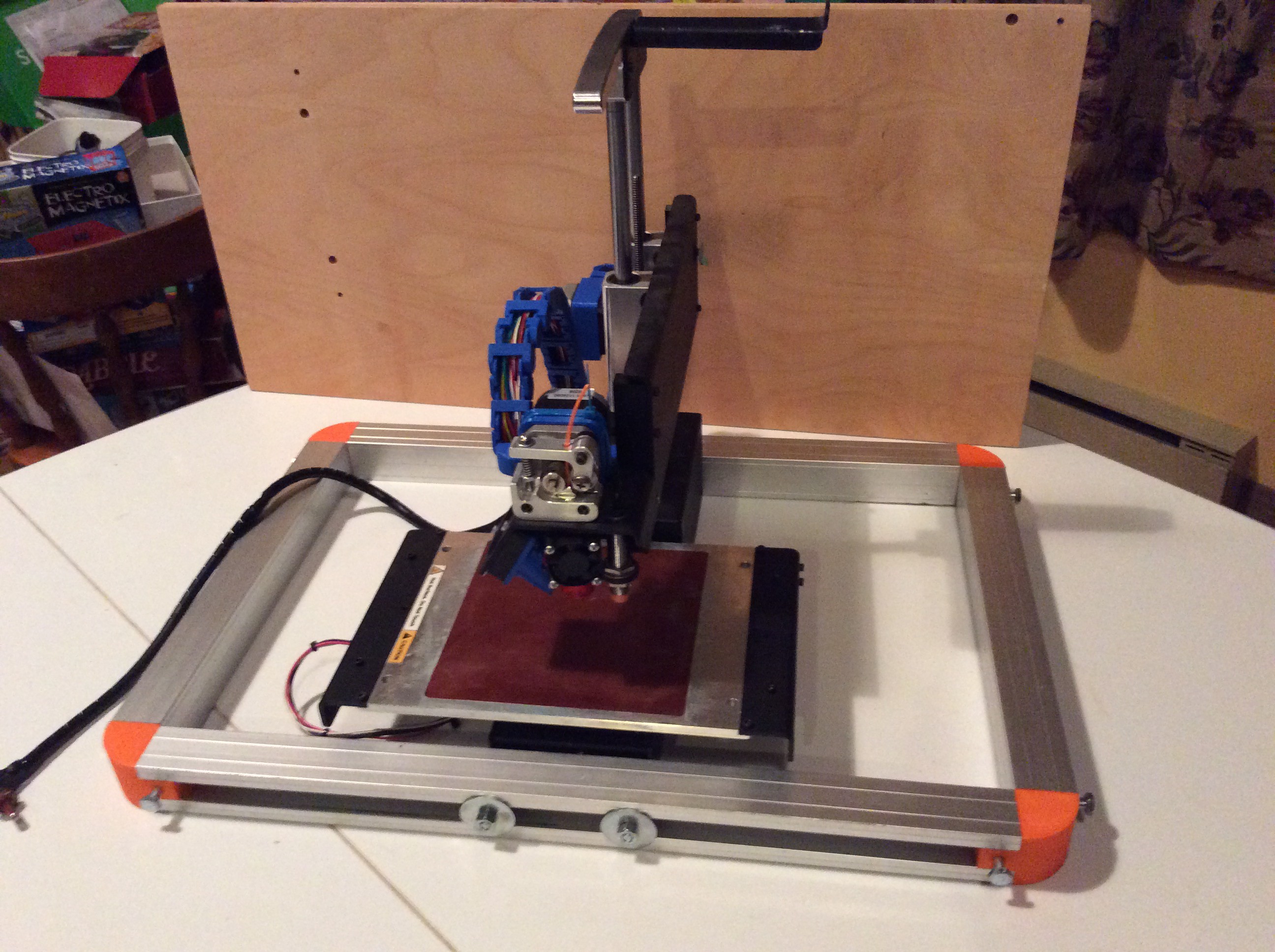
01/28/2016 at 19:03 • 0 commentsFor my frame corner fastening method I opted for single nuts (2 per corner) inset in a 3d printed corner bit and external bolts that tighten against the back wall of the aluminum channel.
![]()
Longer bolts attach the aluminum channel frame to the nose of the stock printrbot body. I put a blocking shim between the frame and body to provide a larger surface to spread forces upon.
![]()
I may put a block in the channel for rigidity and stability of the interface of the body and frame.
Other bits to develop include some sort of mount for the power supply and a spool holder.
-
I've Been Framed!
01/27/2016 at 04:07 • 0 commentsI received my frame pieces yesterday. Nice clean cuts.
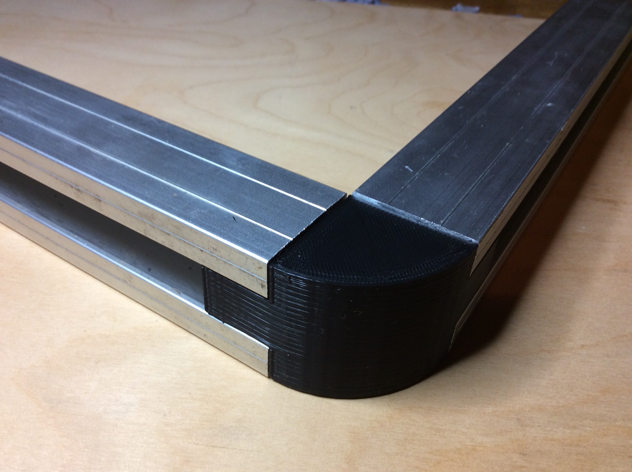
I printed a proto-corner for dimension checking and only slight modifications were needed.
![]()
Now I have to decide what form of attachment method to use. I came up with a novel idea for keeping the frame together; a channel runs through the corner in an arc and allows for a bungee cord or cable to be run through it. This cabling can be tightened to hold the frame together.
Another way to hold the frame together is using inset nuts and bolts or screw to tighten against the back wall of the channel.
![]()
Choices...
-
Too much for 8mm rails...
01/26/2016 at 01:41 • 0 commentsMy suspicion that there was too much bed weight was confirmed when I did the
initial assembly. The 8mm rails did bow too much for use as-is. In fact they bowed so much there was a bed height difference of almost 15 mm from edge to center. Not usable...![]()
So, to rectify, I disassembled again and put the old bed back together. I am printing out new ends and bushings to accommodate a 12mm rod. Probably overkill, but it is what I have right now. These were initially intended for the Z-axis extension, but it will have to wait.
On the up side, I managed to reset the configuration to the larger bed size without too much trouble. First, I did up a custom machine in Cura, specifying the new dimensions. Then using the G-code command line in Cura, I reset the X axis max. Seemed to work without a hitch.
BTW, the green stuff on the bed is 3D-Eez, a surface coating that makes every print stick. I love it.
-
The Bed
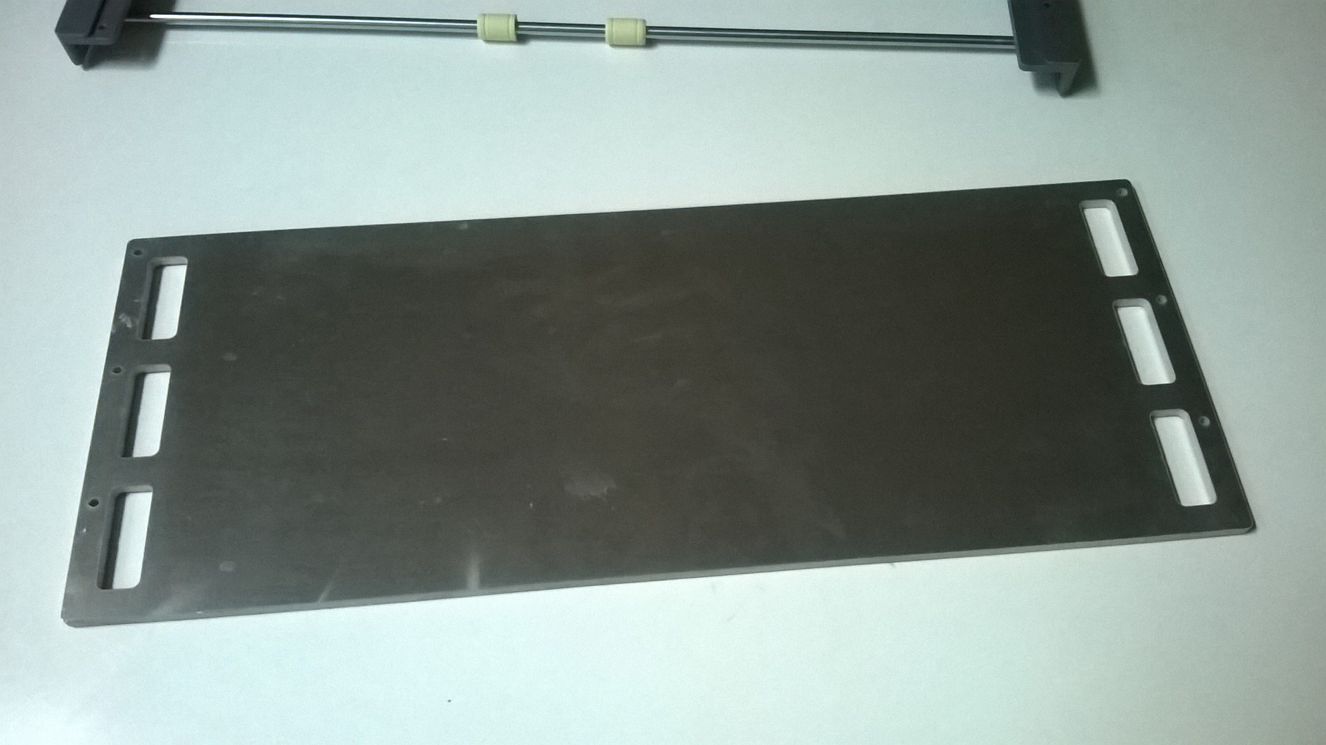
01/22/2016 at 20:48 • 4 commentsi just picked up my new printer bed! As I wrote in a previous log, I decided to keep the option for a y-axis extension open and had my bed water jet cut to accommodate a roughly 10 inch y-axis from the 6 inch limit of the original bed.
![]()
Weight may be an issue. This 6061 aluminum bed weighs 2007 g. Supporting this amount of weight causes a slight bend in the x-axis rods. When the bearings are locked down, they will be more effective at keeping the rails straight. I will continue to assemble as is and see what happens to prints.
To lighten up the print bed, the bottom side could be milled out to the size of the PCB heaters. This would not only cut the weight of the bed almost in half, but would also reduce the thermal mass enabling faster heating and cooling of the print bed.
If reducing the weight does not solve the rod bending issue, a move to 10 mm rods may be in order.
Another consideration with more weight is the drive system: can the drive system handle it? Will belt slippage become an issue? Overheating of the stepper motor?
Tune in next time and find out!
Printrbot 'SuperSize Me" Mod
Transforming the humble 150x150x150mm stock print bed of a printrbot simple metal to a whopping 500x500x150mm
 ken.do