The SAME70 is a powerful microcontroller, it has a lot of peripherals.
For the SAME70-M1, the main function are: - to get the data from the IMU SENS - to communicate with the xBee-M1 for real time control - to get instructions from the SAME70-M1 - to control the motors using the PWM signals
For the whole picture The SAME70-M1, communicates with the SAME70-M2, and the SAME70-M2 communicates also with the RPi Compute Module. The SAME70-M1/M2 are linked to the xBee-M1/M2. I used the schematics of the evaluation board of the SAM70Q as reference, and followed the reference manual of the SAME70 series. Here is the first result. This circuit will be common to the SAME70-M1/M2/R1/R2.
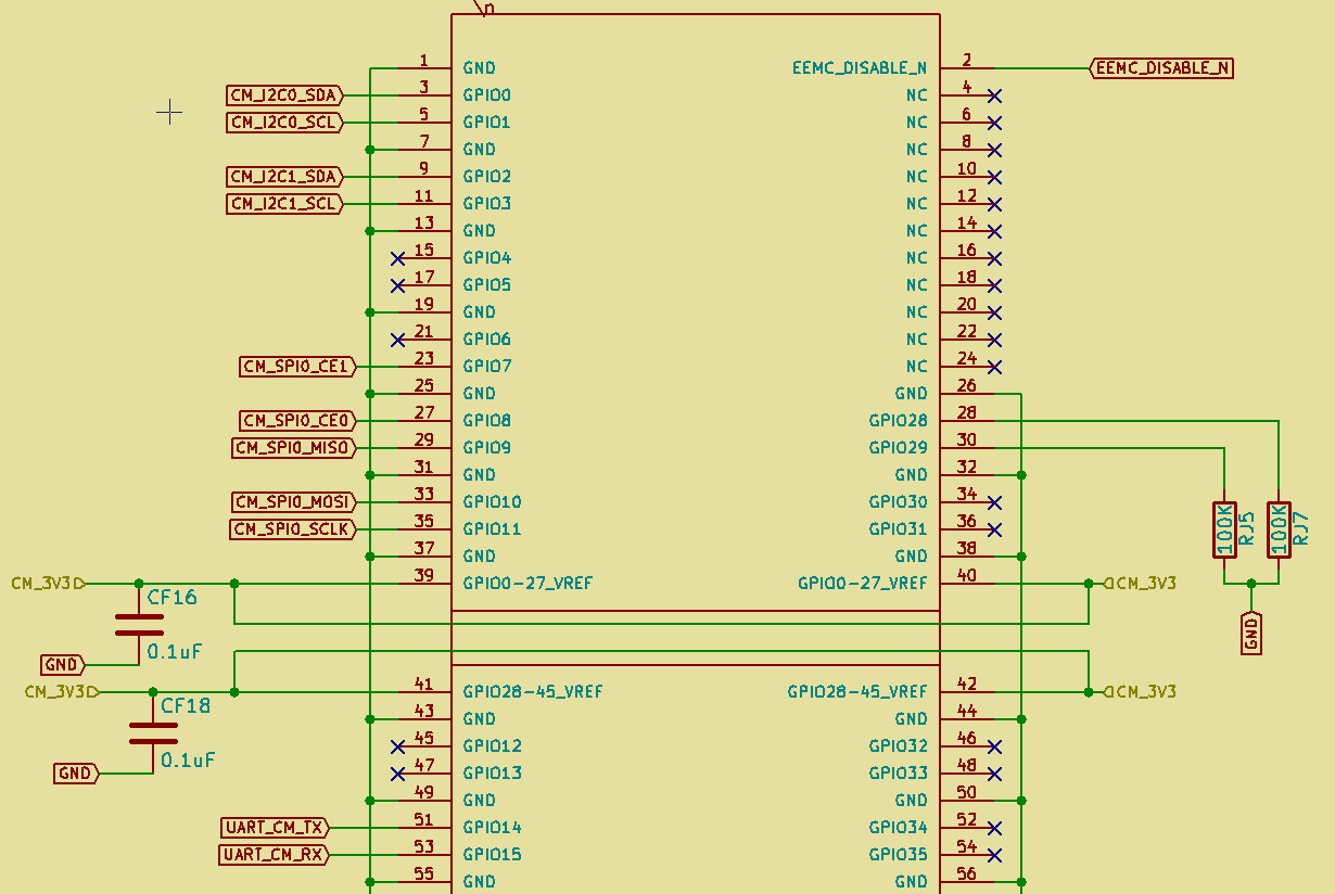
The only differences it the use of the different ports. The following are the ports used by the SAME70-M1. The following are the ports for the SAME70-M2 Mainly used for non critical sensors (GPS, current sensors, LiPo cells voltage sensors...) I use a PFC connector with 30pins to link the FRONT SENS The compute module is connected to the TOP PCB using the DDR2-SODIMM socket.
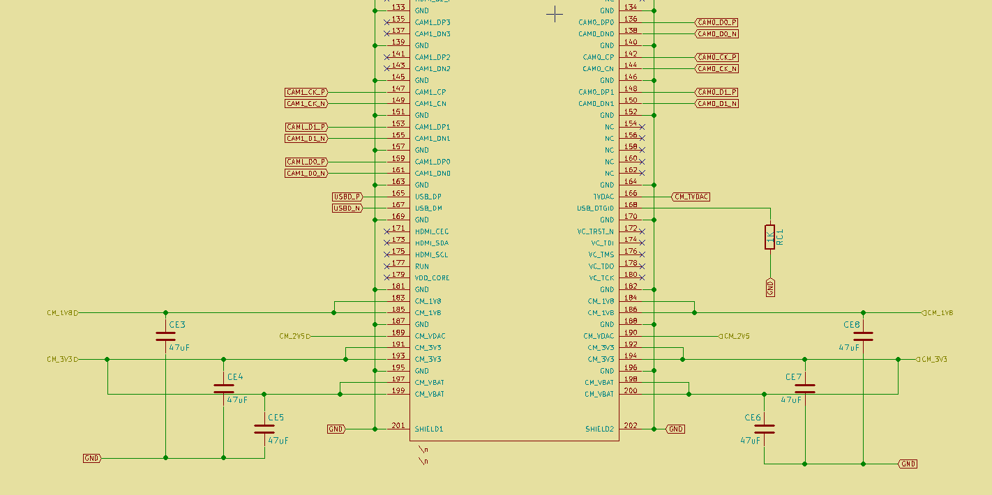
Lot of them will not be connected, the main used pins are described in the following circuit. I used the schemactics from the Raspberry Pi foundation website as reference. The compute module is powered using 1V8/3V3/2V5.
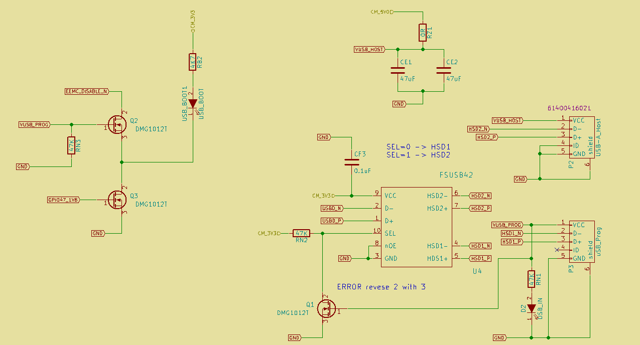
The PCB TOP will have a micro USB for programming the RPi Compute Module and a USB-A for peripherals.
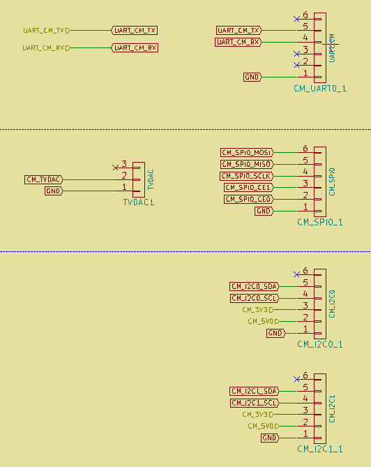
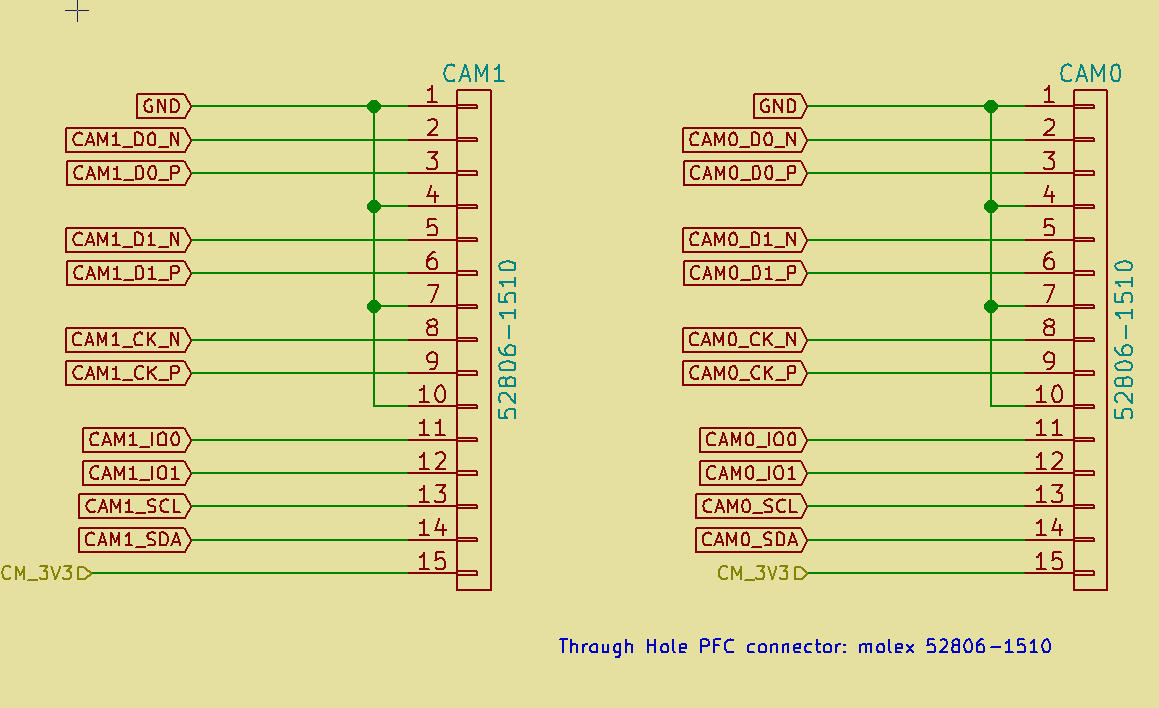
I added a connector for TV DAC in case if we want to use a video streaming. There are two camera connectors, hope to be able to set stero vision using the RPi CM. To power the RPi CM the DCDC converters of 1V8 and 2V8 are placed on the PCB TOP.
I didn't expect from the remote controller to be complex, in the idea it was simple, but when you put the content on paper you realize that it will be as complex as the TOP PCB.
1.5.0.Constraints
Need to have a placement for an LCD screen. In case if the user wants to make local extra hack with a display.
Shall have the neck string attachment.
1.5.1.LEDs/Buttons
Will have a bunch of buttons and LEDs. But mainly: - to monitor radio connection status - to turn on the drone - to arm the motors - to make buzz the drone - ...
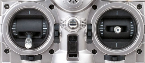
1.5.2.Analog Stick
The idea is to have the same analog sticks as TRANIS.
1.5.3.xBee for telemetry
It will have a xBee for telemetry, that communicates with the SAME70-M2 in the PCB TOP.
1.5.4.xBee for real time control
We use a seperate xBee for real time control
1.5.5.SAME70-R1 for real time control
I can use only one microcontroller, but the idea is to have full dedicated computing unites for more flexibility and availability.
No headaches with cycle constraints or code optimization or tasking.
1.5.6.SAME70-R2 for telemetry
It will communicate with the telemetry part of the PCB TOP
It will have the possibility to send data to a computer if connected to the uUSB;
1.5.7.Connectors for external interfaces
uUSB for programming the SAME70-R1 and R2
The uUSB used for programming the SAME70-R2 will be used to communicate with the computer.
There will be connector for the FR'SKY analog sticks
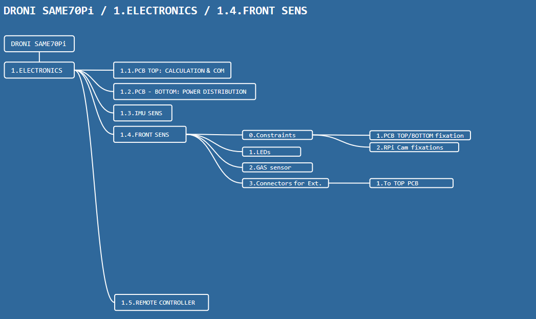
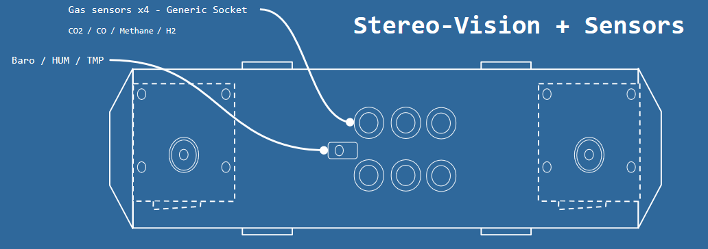
The aim of the FRONT SENS card is to hold some sensors and/or the RPi Cams.
It shall respect the fixation position in the PCB TOP and PCB BOTTOM. It shall have the same connector as the PCB TOP. For this example we will use two RPi Cam and gas sensors:
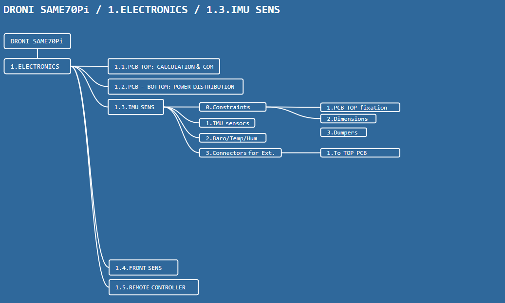
The IMU SENS modules embed 6x IMU chips and 2x baro/temp/hum sensors. The idea behind having multiple IMU sensors is to allow the user the get a better accuracy event in high/low accelerations.
1.3.0.Constraints
The dimensions of the IMU SENS and the dimensions shall be compliant with the PCB TOP. The fixation to the PCB TOP shall be possible through dumpers.
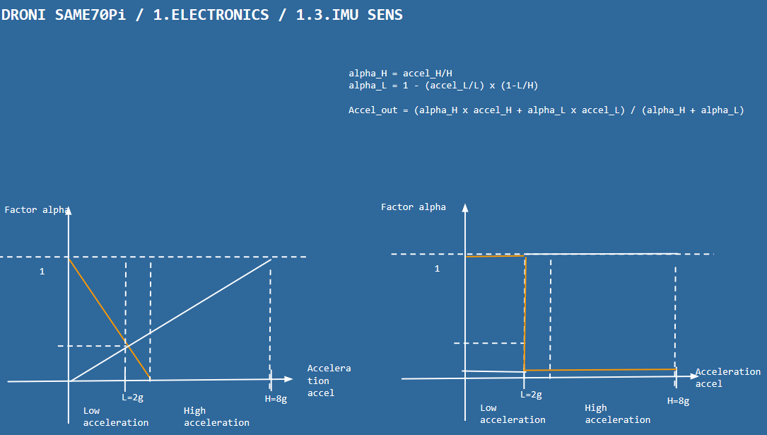
The IMU SENS shall use the following sensors for initial sensing: - 2x BMI160 for 2g sensitivity - 2x LSM6DS3 for 8g sensitivity - 2x LSM9DS1 for 16g sensitivity
The IMU sensors shall be redundant.
The acceleration fusion is selected according the the sensitivity and the current measured acceleration.
1.3.2.Baro/Temp/Hum sensors
The IMU SENS shall use the 2xBME280 sensor for temperature, pressure and humidity sensing.
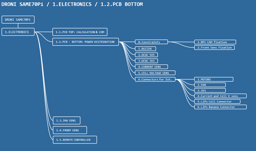
The PCB BOTTOM is in charge of the power distribution from the LiPo to the motors and the PCB TOP.
1.2.0.Constraints
I'd like to place the RPi Cams on the drone to watch down stream. I need to place RPi Cams fixations in the PCB BOTTOM. It shall have 3x fixations, 2x stereo and one in the middle, to have different choices.
It shall have FRONT SENS fixations, like the PCB TOP.
It shall have LiPo fixations and space.
1.2.1.Buzzer
Need to have a buzzer (loudy) in case if the user wants to make the drone buzz remotely or when the LiPo is almost empty.
---------- more ----------
1.2.2.DCDC 5V0
The 5V0 is aimed to power everything.
The converters shall provide enough power for the sensors, the SAME70 and the RPi CM.
It is evaluated approximately to 3A. (2A for the compute module)
1.2.3.DCDC 3V3
The 3V3 will be used to power the SAME70 and some sensors.
Power estimated to 1A.
1.2.4.Current Sensing
The PCB BOTTOM shall have a current sensing. The idea is to measure the current provided by the LiPo to estimate the remaining power or simply for monitoring.
1.2.5.LiPo Cells Voltage Sensing
To have an accurate estimation of the remaining power and speed of discharge, we can measure the voltage of the cells of the LiPo.
The voltage of each cell of the LiPo is sent to the TOP PCB (SAME70-M2) .
1.2.6.Connectors for External Modules
The PCB BOTTOM shall have the following interfaces: - soldered banana wire for the 4x motors/ESCs - 5V0 power source to the TOP PCB for the 1V8 2V5 converters + the sensors - 3V3 to power the SAME70 and the sensors - voltage to measure the current to SAME70-M2 - voltages to measure the cells of the LiPo to SAME70-M2 - soldered banana wire for the LiPo Battery
After thinking, it will be preferable to remove the 1V8 and 2V8 from the bottom PCB. They are used by the RPi CM, and there is risk if IME perturbations. The alternative is that the PCB BOTTOM provides only filtered 3V3 and 5V0. The DC/DC 1V8 and 2V5 converters will be placed directly in the TOP PCB.
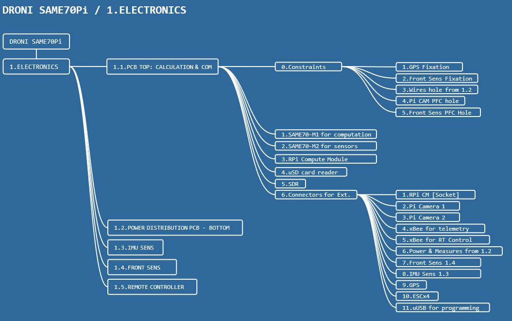
The calculation and data processing is handled by the PCB TOP electronic card.
1.1.0.Constraints
The TOP PCB shall have - the GPS fixation holes - the front sens fixation holes (2x holes) - the wires holes that link the power distribution
We need to have flexibility to position the Pi Cams either in the bottom or the front. The TOP PCB shall allow passing the PFC cable of the Pi Cam through holes.
The TOP PCB shall be powerable using a uUSB for tests. It will be heavy if we require the powering from the BOTTOM PCB, specially during debug phase of the microcontrollers.
The TOP PCB shall have the possibility to add connectors for each UART for debuging.
---------- more ----------
The same thing with the front sens card, the link between the front sent and the TOP PCB is done with a cable. The TOP PCB shall have a hole to allow passing it.
1.1.1.SAME70-M1
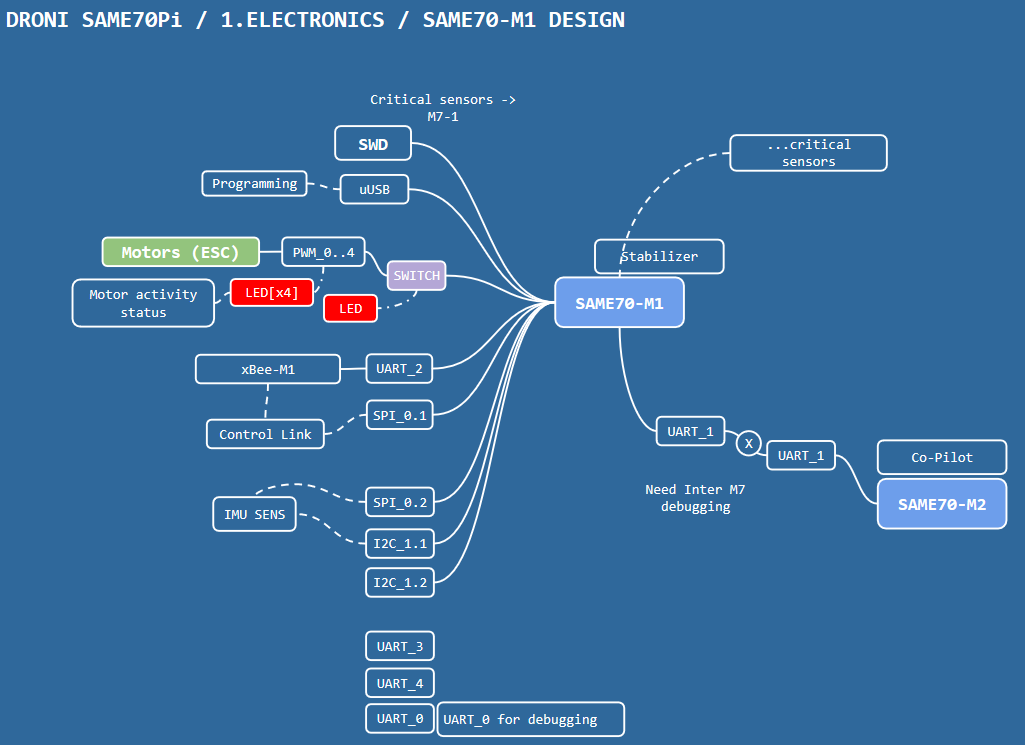
In charge of controlling the motors, stabilization, directional adjustment. The critical calculations (stabilization, motor control,...) is done by the SAME70-M1 uC. It gets directly the IMU data from the IMU SENS. It communicates the secondary uC SAME70-M2 to get instructions (GPS data, initialization & arming,...etc) through a UART interface. It isn't not interfaced with the FRONT SENS. It is programmed using a uUSB on the TOP PCB. It is interfaced with the xBee-M1 in charge of the control (manual navigation and critical instructions).
1.1.2.SAME70-M2
In charge of telemetry data, navigation instruction.
The IMU data is retrieved from the SAME70-M1 (not directly from the IMU SENS). It gets the data from the GPS through UART. Most of the GPS are UART driven. It communicates with the RPi CM using UART. It is interface with the FRONT SENS. It gets the current of the LiPo from the BOTTOM PCB. It gets the voltage of each cell of the LiPo from the BOTTOM PCB. It is programmed using a uUSB on the TOP PCB. It is interfaced with the xBee-M2 in charge of the telemetry.
1.1.3.Raspberry Pi Compute Module
The RPi CM is in charge of heavy data processing, imaging, navigation plan,...etc. It get the processed data from the GPS, IMU, Sensors,...etc from the SAE70-M2.
It is interfaced with the SAME70-M2 using UART. it is interfaced with the SDR circuit using SPI + selection. I checked the circuits that uses a SDR, most of them are SPI driven, I suppose mostly we will use the SPI too. it is interfaced with the uSD card using SPI + selection.
I add a USB-A to the TOP PCB for peripheral of the compute module. Am thinking about a WiFi dongle.
1.1.4.uSD Card
It is used to store user defined data by the RPi CM.
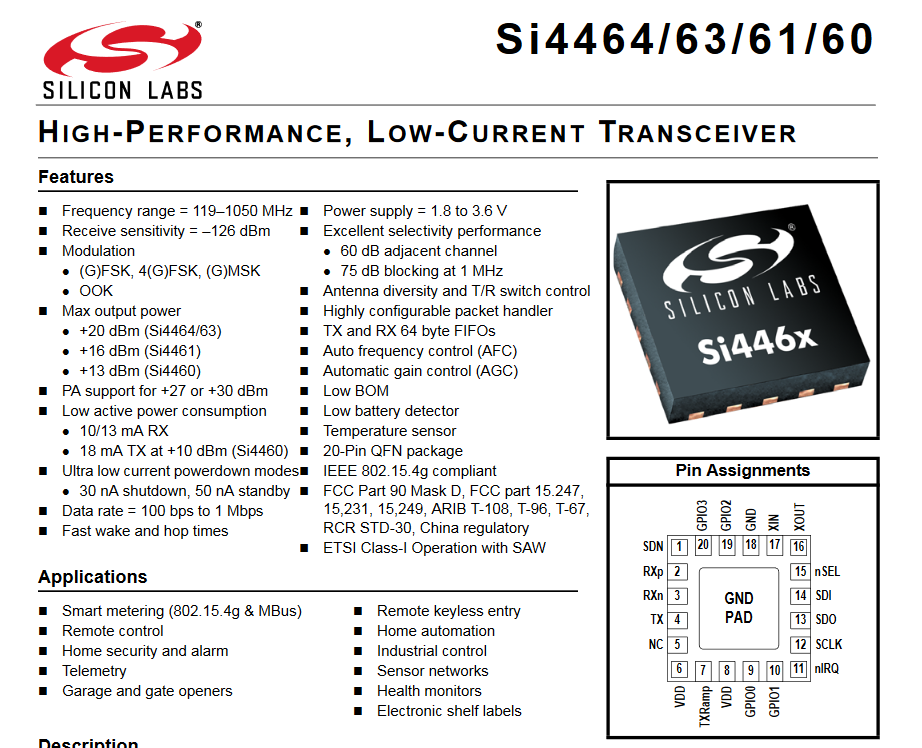
1.1.5.SDR
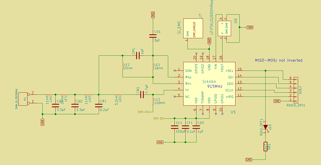
The idea is the have additionally a software defined radio embedded in the TOP PCB. I played with the Si4464, I thought it might be interesting to add it. Since the SAME70-M1 and M2 both have xBee to talk with, it might be interesting if the RPi CM has also it's radio.
1.1.6.Connectors for external interfaces
The TOP PCB shall provide connectors and sockets for the following modules: - the Raspberry Pi Compute Module - RPi Cameras - xBee modules - BOTTOM PCB - FRONT SENS - IMU SENS - GPS - ESC (PWM) - uUSBs for programming
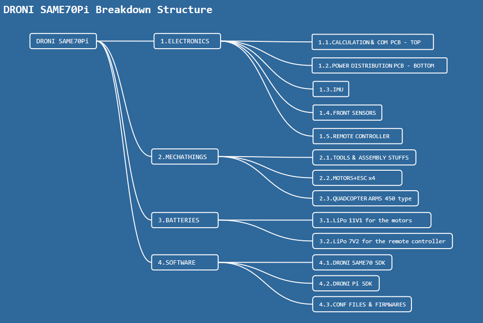
If I break down the platform it will have two sets: - electronics that I will design and build (assembled electronic cards) - mechathings the cots items for mechanical, assembly tools, brushless motors,... - batteries - software the SDK for the SAME70 and the Raspberry Pi Compute Module
The main composition can be described in the following breakdown structure.
The main part that requires lot of works is the software part to setup a SDK to make easy the software development on the drone, I will start it as soon as I finish the hardware design. But now we focus on the hardware thing :)
The following detailed breakdowns will gather also the user needs of the composition of the platform.
 Laetitia BEL
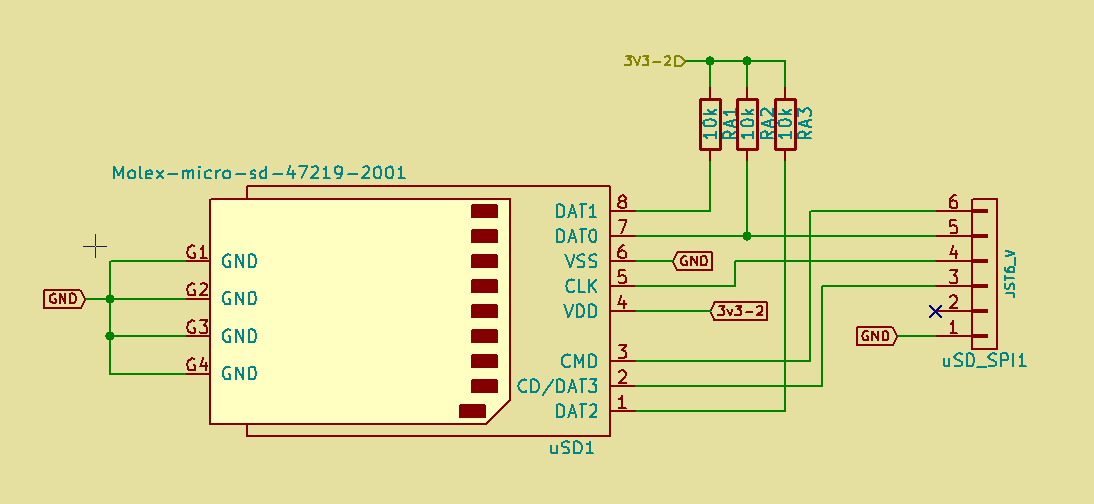
 For the whole picture
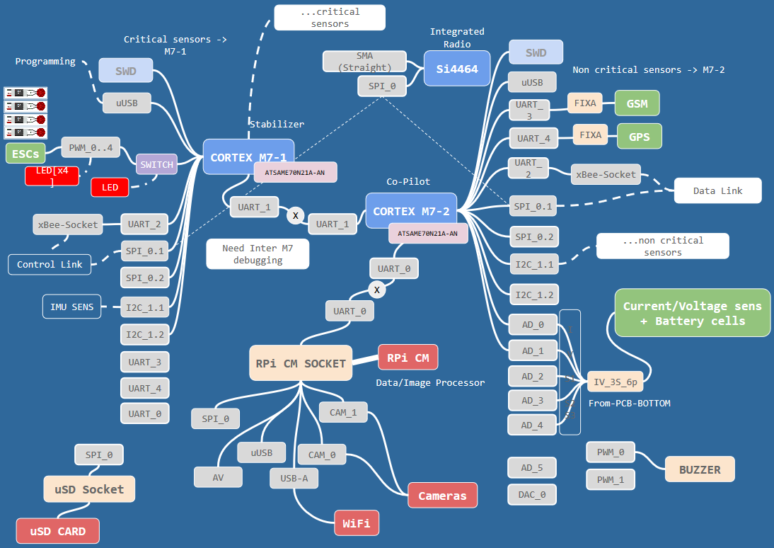 The SAME70-M1, communicates with the SAME70-M2, and the SAME70-M2 communicates also with the RPi Compute Module.
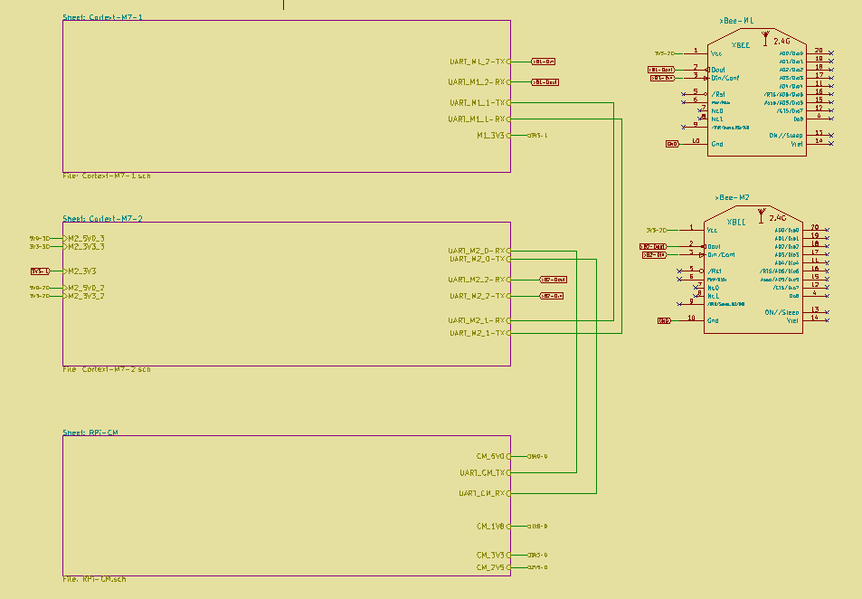
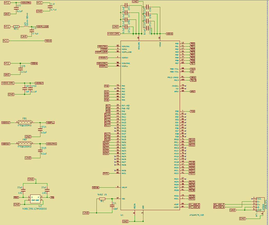 This circuit will be common to the SAME70-M1/M2/R1/R2.
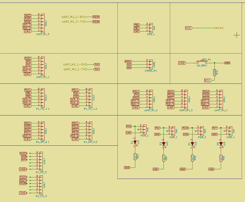 The following are the ports for the SAME70-M2
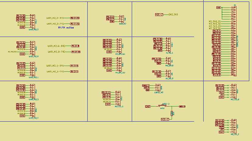
 To power the RPi CM the DCDC converters of 1V8 and 2V8 are placed on the PCB TOP.
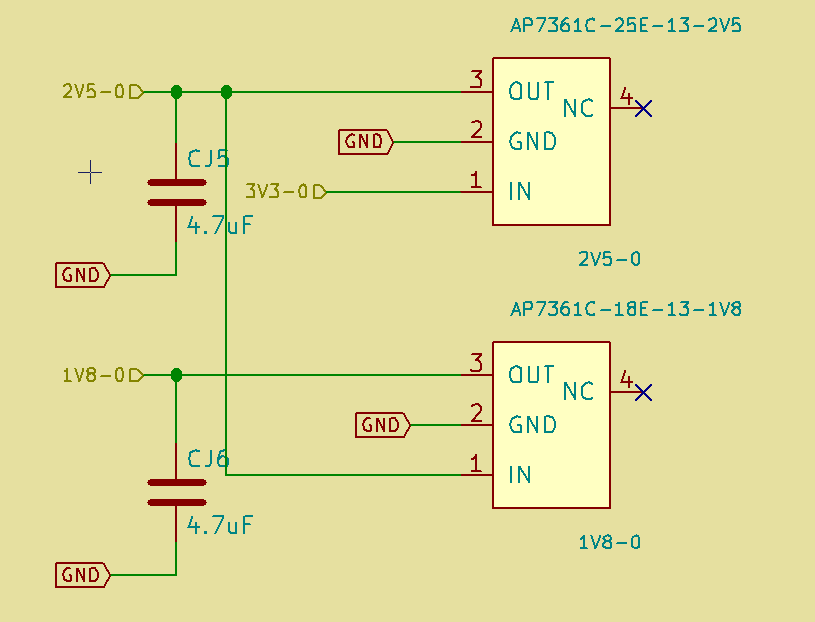

 The main part that requires lot of works is the software part to setup a SDK to make easy the software development on the drone, I will start it as soon as I finish the hardware design.