Close
0%
0%

Yet Another Pi Zero USB Hub

Thought you'd seen enough Pi Zero USB hubs? You're Right!3-port USB hub, 12 V power in (2A capacity), and audio output for the Pi Zero

Similar projects worth following
Yet another Pi Zero USB Hub. This hub adds a 3-port USB hub, 12 V power in (2A capacity) with a barrel connector, and audio output for the Pi Zero through a 3.5mm stereo jack.

This USB hub is meant to stack on the bottom of the Pi Zero. It provides 3 USB ports, audio output, and a power supply from a 12V wall wart.

This is not a product and it never will be; it's something I've designed to be as small and as capable as possible. This means hot glue and random wires soldered everywhere. These wires will be hidden, yes, but this is not a 'professional' solution. It's a solution that's as small and as capable as possible, while still doing everything I want it to do.

  • Doing the BOM

    Benchoff01/12/2016 at 02:04 0 comments

    A few more revisions until I'm away from Eagle for a few weeks. I've updated the schematic, fixed a few major issues, and added an audio amplifier. Yes, it's a fantastically stupid idea, but I can see the value in having an optional 2 Watt class D audio amp on this board.

    With that addition, I've run out of room on the board. Therefore, it's time for the BOM.

    Part Value Device Digikey Part No. Unit Price 1k
    C1 10uF CAP_POL1206

    C2 10uF CAP_POL1206

    C3 0.1uF 0.1UF-25V(+80/-20%)(0603)

    C4 0.1uF 0.1UF-25V(+80/-20%)(0603)

    C5 10uF CAP_POL1206

    C6 10uF CAP0603-CAP

    C7 10uF CAP0603-CAP

    C8 0.1uF CAP0603-CAP

    C10 10uF CAP0603-CAP

    C11 10uF CAP0603-CAP

    C14 33nF CAP0603-CAP

    C15 33nF CAP0603-CAP

    F1 PTCSMD PTCSMD F2110CT-ND 0.22
    F2 PTCSMD PTCSMD F2110CT-ND 0.22
    JP1 POWER_JACKPTH_BREAD POWER_JACKPTH_BREAD Adafruit 373 0.76
    JP2 3.5mm Audio Jack SMD AUDIO-JACKSMD2 CP-43515TSSJCT-ND 0.59
    Q1 12MHz CRYSTALCTS406 CTX855CT-ND 0.75
    R1 2.7k RESISTOR0603

    R4 270R RESISTOR0603-RES

    R5 270R RESISTOR0603-RES

    R7 150R RESISTOR0603-RES

    R9 150R RESISTOR0603-RES

    S1 SWITCH-MOMENTARY-2SMD-1101NE SWITCH-MOMENTARY-2SMD-1101NE CKN10388CT-ND 0.33
    USB1 USB_TYPE_A_FEMALE_TH USB_TYPE_A_FEMALE_TH A31726-ND 0.797
    USB2 USB_TYPE_A_FEMALE_TH USB_TYPE_A_FEMALE_TH A31726-ND 0.797
    D3 PRTR5VV0U2X PRTR5VV0U2X 568-4140-1-ND 0.202
    Power IC buck regulator TPS62143RGTR 296-39448-1-ND 0.99
    D1 PRTR5VV0U2X ESD Protection Diodes 568-4140-1-ND 0.202
    D2 PRTR5VV0U2X ESD Protection Diodes 568-4140-1-ND 0.202
    R10 CRCW0402100KFKED 100k Ohm 0402 541-100KLCT-ND 0.02
    L1 IHLP1212BZER2R2M11 IHLP1212BZER2R2M11 541-1322-1-ND 0.75
    C18 TMK316BJ106KL-T 10uF cap 1206 587-1337-1-ND 0.07
    C17 TMK316BJ106KL-T 10uF cap 1206 587-1337-1-ND 0.07
    C16 TMK316BJ106KL-T 10uF cap 1206 587-1337-1-ND 0.07
    IC3 TPA2016D2RTJR TPA2016D2RTJR 296-25430-2-ND 1.46
    USB FE1.1S FE1.1S N/A 0.66

    capacitors and resistors aren't free, but they're free enough. I did the math for 1k units on this, just to demonstrate how fantastically stupid manufacturing this would be.

    In 1k quantities, the BOM for this board is $9.16. With the resistors and caps and board, it's going to be $10. If this were a product, it would sell for $20-25 without the Raspberry Pi Zero, or just a tiny bit less than a proper Raspberry Pi.

    Nevertheless, there's a value in making stuff small, so I'll be making a few of these for personal projects. The github for this project has the updated schematic.

    The next task, before sending this out for a real fabrication, is a refactor of the entire project. Looking over the BOM, there are some fantastically stupid choices here.

    Here's a digikey cart

  • First Design Revision

    Benchoff01/09/2016 at 15:14 0 comments

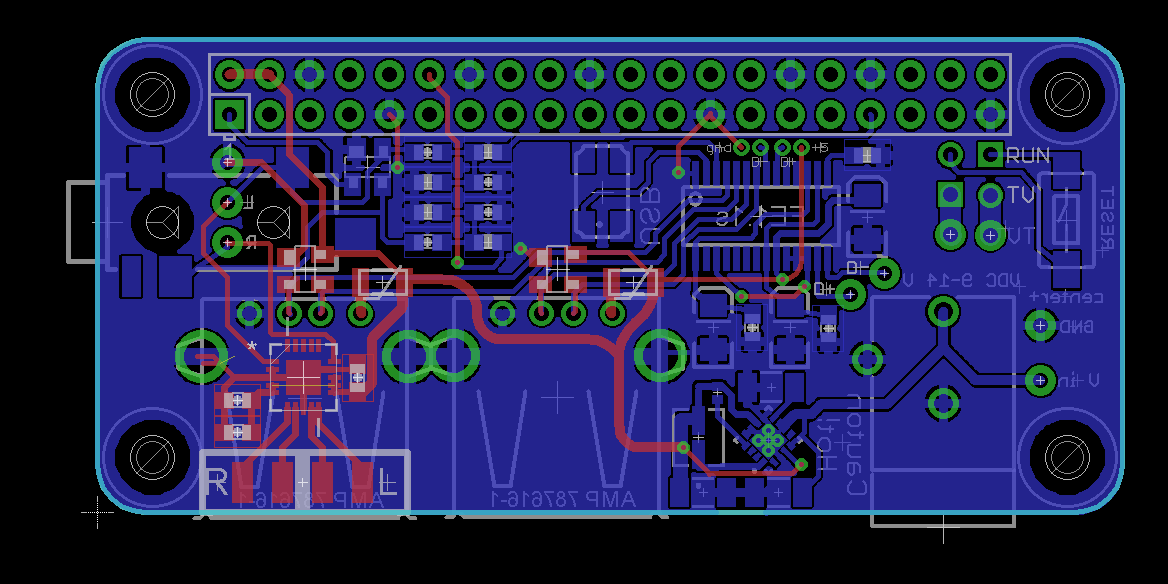
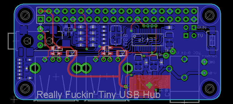
    The boards are already off to OSHPark. Here's what I'm looking at:

    This is probably the smallest and most compact PCB I've ever designed. It's composed of three sections: the USB hub, the Audio output, and Power supply.

    The USB hub

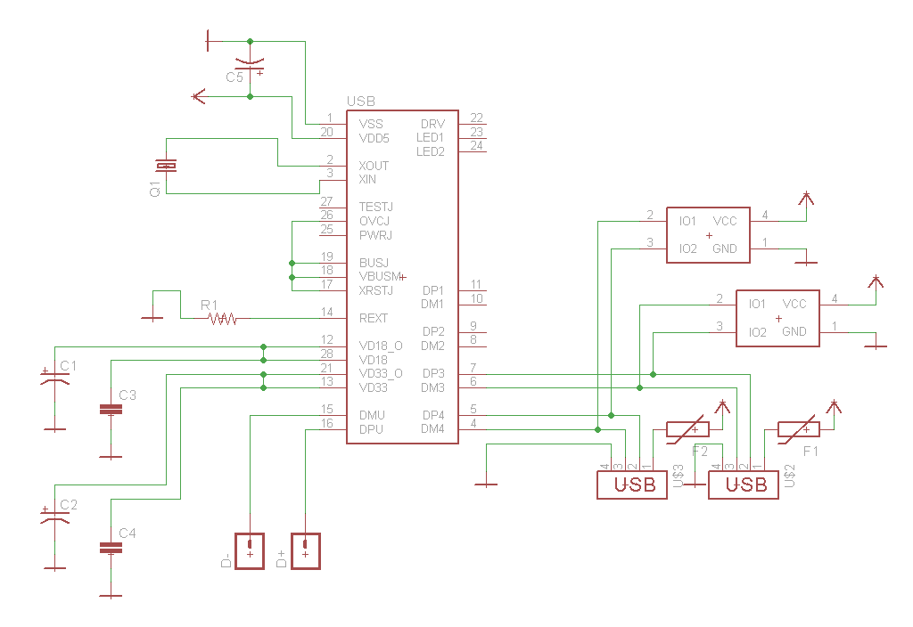
    Everyone needs to build their own USB hub! It's the zeitgeist of the Raspberry Pi Zero. This hub is built around the FE1.1s 4-port USB 2.0 hub controller. This chip doesn't require pullups, pulldowns, extra power regulators, and operates at full speed (12MHz). I have 10 chips coming to me via eBay and China.

    I broke out two USB ports in this four-port hub. Because I envision this project being used in a few projects where space is at a premium, I've also added solder pads for the power, ground, D+ and D- of a third USB port. An Edimax WiFi module can easily be added with some wire, solder, and hot glue.

    The upstream port connects to the Pi through solder pads. The D+ and D- pins of the OTG port are available on the back of the Pi Zero, labeled as PP22 and PP23. This is more solder and hot glue; this board is intended to stack tightly against the Pi Zero - there shouldn't be any issue of the wires pulling out.

    Protection of the USB ports is done through ESD diodes and a polyfuse. This isn't a completely protected port, but it's better than nothing.

    Audio Output

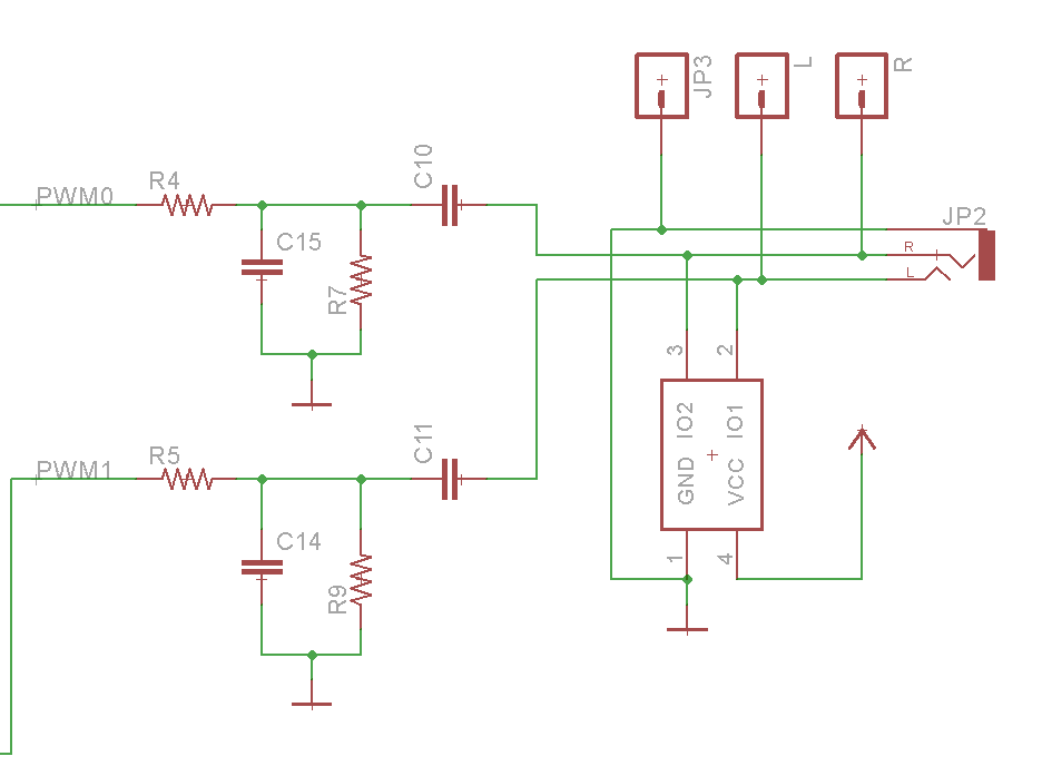
    The Pi Zero doesn't come with audio output. Because the Pi can play audio through it's PWM peripherals, adding audio doesn't take up that much space. The instructions are given by lady ada, and implemented with standard value parts.

    The same part number for ESD diodes as used in the USB ports is used here in the audio port. Output is though a 3.5 mm jack, or if this project will find its way into something that requires even less space, solder pads for left, right, and ground.

    Power Supply

    Although it takes up the smallest area on the board, the power supply has had the largest consideration of anything in this project. Instead of a microUSB port, I'll be powering this project through a wall wart, delivering 12VDC. This 12VDC is also broken out to solder pads, as a lot of cheap TFT displays exclusively use 12VDC

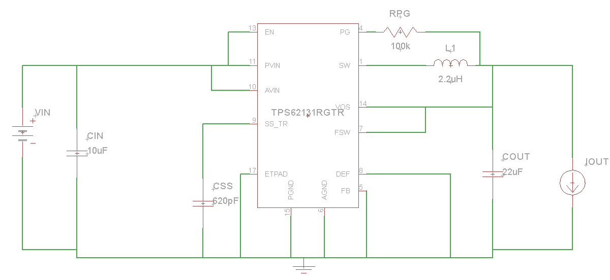
    The design for the power supply is able to accept anything between 9 and 14V, delivering 2A at 5V. This is a high performance power regulator, and for this project I'm using TI's TPS62141. Design was generated by TI's WEBENCH software. This power supply is overkill, and there are other parts in the family that would be better suited for less powerful builds.

    Actually Building it

    the boards are off at OSH park, and in two weeks I'll be gone for a month. This is going to take a while to put together. If the first one works, I'll make about three or five of these things. I can see this being useful for a few projects, at least.

    Files are available in the github, improvements in layout and design will be made.

View all 2 project logs

Enjoy this project?

Share

Discussions

AVR wrote 11/10/2016 at 05:09 point

sweet, the audio out is nice. May have to build one up this will be great for puredata on my pi zero

  Are you sure? yes | no

xemexe wrote 01/30/2016 at 16:23 point

Schweeet !!

  Are you sure? yes | no

Similar Projects

Does this project spark your interest?

Become a member to follow this project and never miss any updates