Arduino Enigma
-
12/23/2017 - Putting the Display and Keyboard together.
03/18/2018 at 18:47 • 0 commentsThings are getting serious now. Its time to start putting everything together and getting the component placement finalized. I like to preview the boards by exporting to Gerber and importing into Oshpark
https://oshpark.com/profiles/ArduinoEnigma/
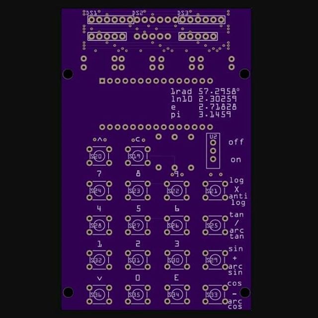
The board below is a quick export job, the vias are untented. For production jobs I like to tent the vias, as nothing gets soldered to them. Fritzing does not support that option (of course), but there is a way to achieve that result. Start by exporting the full board first, then selecting all the vias (Routing->Select All Vias) and deleting them. Then export the gerbers to another folder. Finally, copy the solder mask file from the folder containing the gerber without vias to the folder with the production board.
The logo is left out to see if somebody can identify the board.
![]()
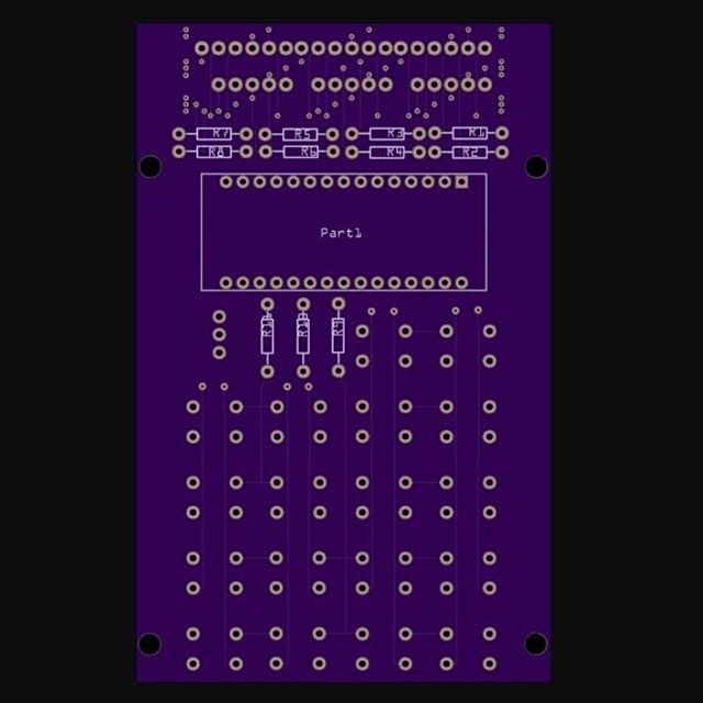
The display resistors, Arduino Nano, and keyboard row selection resistors get soldered in the back.
![]()
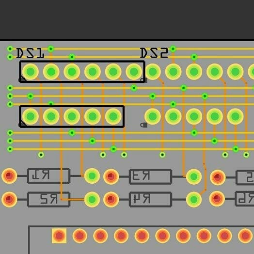
The fully routed LED displays are shown below. The horizontal bus lines tying the same segment together can be seen. The common anodes for the digit selection are routed down to individual vias.
Each segment in the display is routed to a resistor. The other side will be connected to a pin in the Arduino. Perhaps a better routing order is to start from the Arduino and lay wires towards the resistors, then we can choose where to connect the other side of the resistor to the segment, options abound.
What's remaining is to route the common anodes and the other side of the segment resistors to the Arduino Nano.
![]()
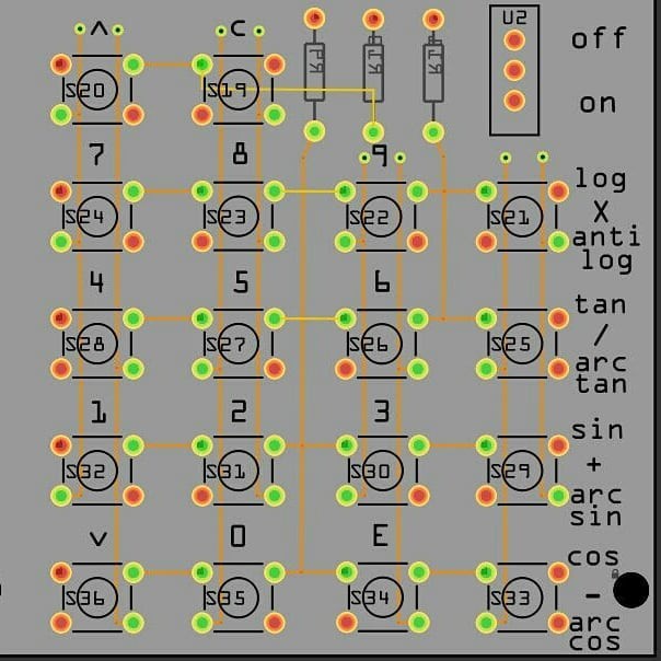
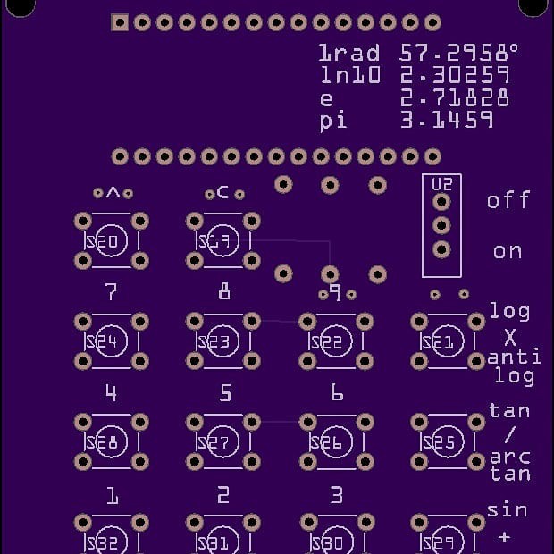
The resistors driving the selection lines are now populated. The eight return lines can be seen terminating in vias above each column of buttons. The circuit has been optimized to do most of the wiring on the bottom side of the board. Only a couple of horizontal lines are in the front. A wishlist item is to have all the traces in the back.
![]()
some details of the board:
![]()
time for a quick instagram post:
-
12/21/2017 - A suitable display is found, design of the PCB continues.
03/18/2018 at 06:33 • 0 commentsA previous search revealed that there were LED modules that were 15mm wide and had 3 digits. We need 3 of those side to side to get the 9 digits a Sinclair Scientific needs. Previous implementations using two packs of 4 bubble LED modules needed a separate LED to indicate the negative sign of the mantissa.
The leftmost digit will only be used to display the sign for the mantissa. The decimal point will be "on" all the time after the middle digit. Digit number 7 will be the negative sign for the exponent. A full display will look like this: -8.8 888 -88 a blank one: 0.0 000 00
The US suppliers are out of stock of the smaller LED modules. Time to visit AliBaba.
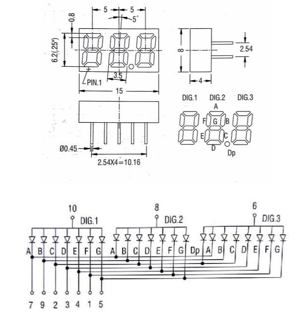
A lot of displays appear, but careful examination of the display datasheets was needed. This fella here looked promising, it has a single decimal point in the right place, but something was amiss with the number of pins. It has 10 pins, 11 pins are needed for a 3 digit seven segment display with a decimal point. The DP segment is tied together with the C segment. Building a truth table, it becomes evident that the decimal point will be "ON" all the time a digit other than 2 is displayed. That's an interesting optimization. I wonder what equipment out there cannot display a decimal point when 2 is showing in the middle digit.
![]()
This is the first time I have used AliBaba, I learn that the suppliers of LED modules there deal in minimums of 100 or 1000 units. The lesson learned here was that for 10 units, go to AliExpress, for 1000 units, go to AliBaba. A single account is good for both sites. Also, a credit card is needed to order in the site. They do not take Paypal. Being leery of using a credit card on an overseas website, I start looking into prepaid credit cards. The ones at the Pharmacies sometimes do not work on overseas websites, one has to read the small print to find that out. Finally, Movo.Cash appears. A separate prepaid virtual card is created that can be loaded through Paypal and used to pay at the Ali sites.
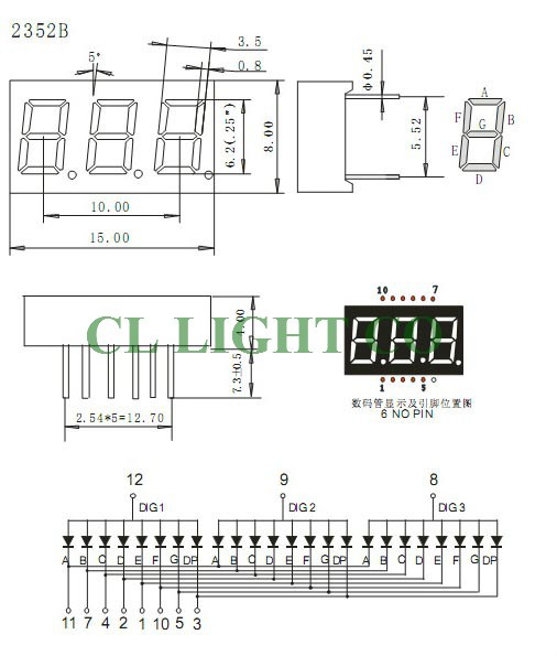
Looking through AliExpress, the following display is found. It has the right number of pins, the decimal point is individually selectable and enough dimensions are given in the datasheet to design a PCB. Note that the pin at position 6 is missing.
https://www.aliexpress.com/item/32803893497.html
https://www.aliexpress.com/item/32613899374.html
![]()
With that information, design on the display side of the PCB can continue.
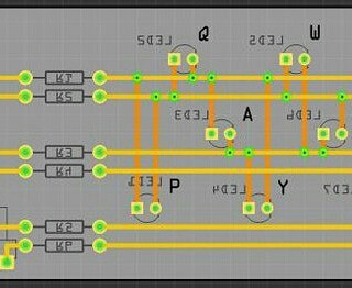
Working on an external lampfield device for the enigma machine simulator, I decided on the following pattern to take the charlieplexed signals to all the lamps in the display. Run all the signals horizontally on one layer and on the opposite layer, run vertical traces to get the desired signals to each LED. An arbitrary LED can be fed from any two pins.
![]()
https://www.instagram.com/p/BWvxGH6FxDG/
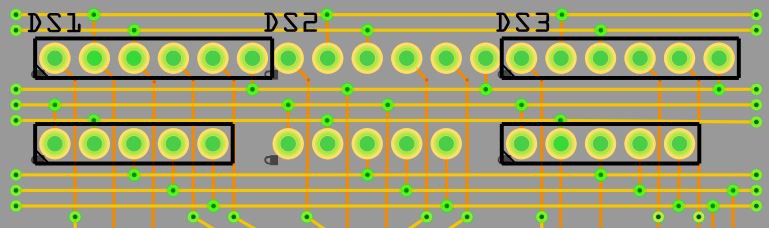
Maybe this design pattern can also be used to wire a multiplexed LED display module. Shown below are the sockets for the three display modules. Frtizing does not have a footprint for this component (of course). So I am using a connector with 6 pins at 0.1 spacing to represent the top row and a 5 pin connector at the bottom. The connectors are placed in the appropriate locations by entering a value in their x/y coordinates. The separation between modules DS1 and DS2 is what I calculated from the datasheet above. We will revisit this decision later.
The leftmost pin (12) on the top connector selects the leftmost digit. Pins 8 and 9 select the middle and right digits respectively. Notice that those pins on each connector are brought to an individual via at the bottom of the circuit. The rest of the pins will be connected to bus lines, represented by the place-holder vias on the left and right sides of the circuit. Three bus lines are laid down and pins 7, 10 and 11 in each display module are connected together using those bus lines. This is enough for a proof of concept. Work can continue.
![]()
Time to go to instagram for a quick post:
https://www.instagram.com/p/Bc9rP__HvXN/
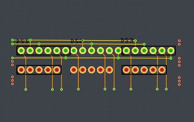
Eventually, the completed circuit will look like this. Pins 12, 8 and 9 (the digit selection pins) for each module immediately go down to a via. The rest of the pins connect to a bus line, with the same pin in each connector going to the same bus line. Notice that the top-most bus line connects pins 11 of each top connector together. That now gives us multiple convenient points to connect this to the microcontroller. In this case, Pin 11 of DS1 is the one that connect to the Arduino Nano. The other two will be fed through the bus line. Similarly, The Arduino connects to pin 10 of DS1, which in turn connects to the second bus line feeding pin 10 on DS2 and DS3
![]()
It begins to look more and more that this whole board will be hand-routed.
-
11/17/2017 - The keyboard is designed.
03/18/2018 at 04:20 • 0 commentsThe beginning and prior art:
Its late October, early November 2017, and Hackaday has been running a series of articles with the Sinclair Scientific Calculator as a subject.
https://hackaday.com/2017/10/24/reverse-polish-notation-and-its-mildly-confusing-elegance/
https://hackaday.com/2017/11/01/a-teardown-with-a-twist-1975-sinclair-scientific-calculator/
https://hackaday.com/2017/11/06/build-a-calculator-1974-style/
A link to an online simulator is published:
http://files.righto.com/calculator/sinclair_scientific_simulator.html
Finding this calculator incredibly intriguing, I begin browsing the calculator section of hackaday io
https://hackaday.io/list/7200-calculator-projects
This calculator looks promising, but it does not have enough keys:
https://hackaday.io/project/15334-retro-taking-calculator-with-bubble-display
This project uses a Texas Instruments MSP430 to simulate this specific calculator
https://hackaday.com/2014/07/02/pocket-calculator-emulates-pocket-calculator/
Both of the above projects use a bubble led display that was briefly available at Sparkfun years ago, but has now become Unobtainium.
I guess I could cheat and use an LCD screen to simulate the user interface:
https://hackaday.io/project/7478-blucalc
I have a KIM Uno, but its a digit short and the key layout does not match.
https://hackaday.io/project/4802-kim-uno-a-simple-kim-1-cosmac-elf-replica
So, its decided, I have to roll a custom PCB, loosely inspired by the KIM Uno, but with the correct key layout and select a suitable LED display. But first, I have to find the LED displays.
After a lot of searching, a cluster of 3 seven segment display appears. Its 15mm wide, making 3 of them back to back 45 mm wide, just under the 50mm width of the calculator. It's hard to find the right part on the usual US suppliers, but at least that's a start.
Having studied the schematic for the KIM 1 / Uno prior to this. I know that the 8 lines that drive the display are temporarily switched to input mode and a separate output pin, connected to a resistor, is used to feed one side of 8 buttons, whose other side is connected to the display lines. If a key is pressed, the display line for that button will change. Since this keyboard has 18 keys and a resistor can select 8 keys at a time, 3 selection lines are needed.
A PCB is quickly laid out with the buttons, and three selection lines going between the key columns, they feed the top contact of the buttons. The bottom contact connects each button to one of eight display lines.
I draw vertical lines in the back, horizontal lines in the front and a PCB begins to take shape. The vertical line connecting to the top contacts of S16 and S15 is the selection line for the rows S16 thru S13 and S12 thru S9. The top two pins for each button are internally connected. The bottom two pins are also internally connected. That makes it easy to design a PCB because the top pins can be daisy chained through the buttons. The vertical lines running through the inside of the buttons return the signal when one button is pushed. The leftmost vertical line returns the signal for S16 when its selection line is activated. S8 can be read through the same leftmost return line when the middle selection line is activated.
![]()
Time for a quick instagram post:
Sinclair Scientific Calculator Emulator
A register level TMS0805 CPU emulator on an Arduino Nano runs the original 320 instruction calculator program. A custom PCB houses it all.