 JLAM
JLAM-
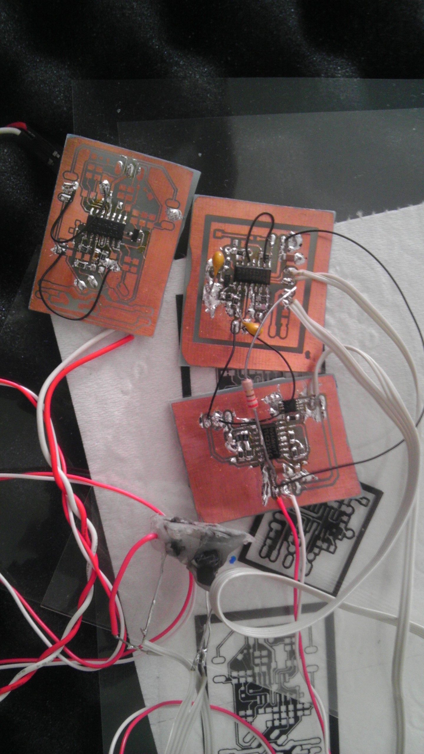
Height Sensor Prototyped
12/16/2014 at 22:36 • 0 commentsJust a quick update, The sensors are prototyped but due to a few noise coupling and filter tuning issues, I don't have any conclusive results. The primary source of EMI was in the ribbon cable carrying the LED drive current which is parallel to the photodiode wires. As the current in the LED wires are orders of magnitudes greater than the photodiode wires, there is a lot of noise in the same frequency as the signal coupled in. Will look into shielding the wires.
![]()
-
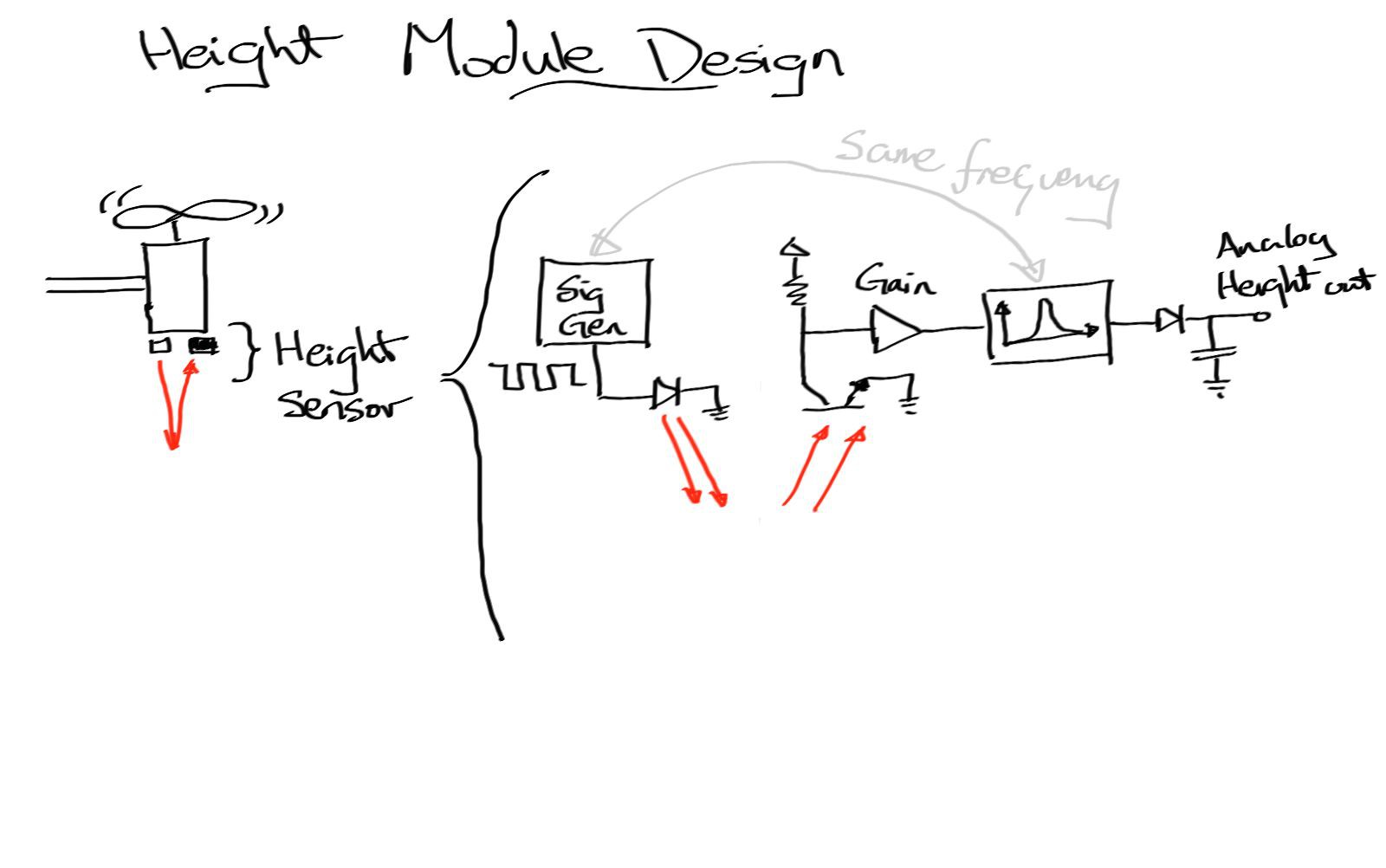
Design update
08/18/2014 at 14:03 • 0 commentsThe pendulum design was getting quite troublesome with need to balance the multiple motors, so I've decided to try creating individual modules that can maintain a constant height. Then hopefully by joining multiple modules I should have a flying object.
The module will use light reflectance to determine height as it is the smallest method I can think of. It will use an arbitrary frequency to drive an LED which is then sensed by a photo-transistor and passed through a bandpass filter to help reduce the effect of ambient light. This should provided the feedback signal to control the motor driver.
![]()
-
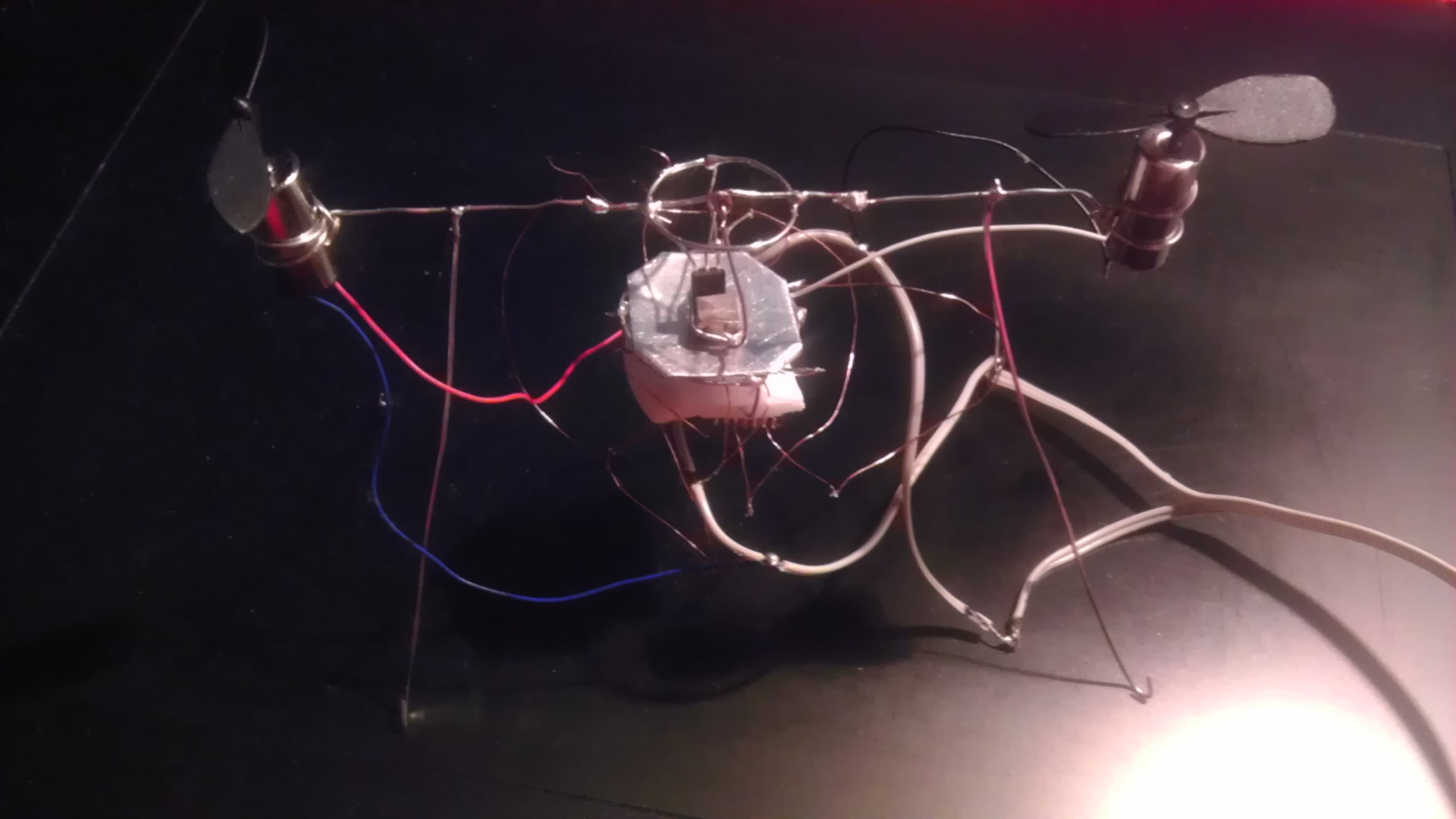
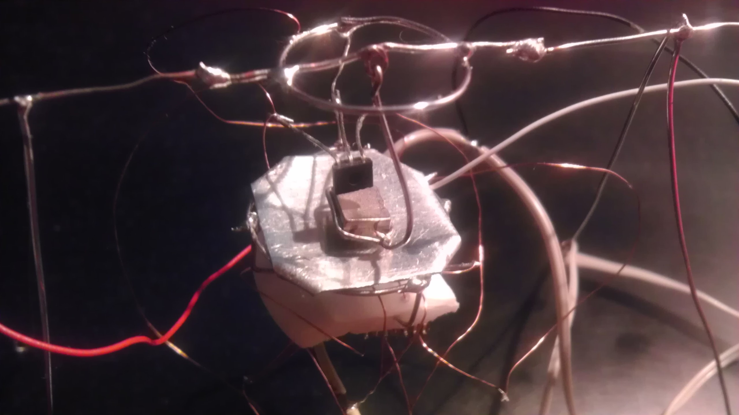
Inital test of pendulum
06/04/2014 at 21:46 • 0 commentsMade a two propeller version to test the pendulum design in one axis. Found that the dampening was not enough and caused the device to oscillate. The next step is to use a spring instead of a free hanging pendulum.
![]()
![]()
-
Pendulums and hall sensor tested
05/16/2014 at 13:25 • 0 commentsMade a pendulum with a magnet attached to the bottom and tested the hall effect sensors. One thing to note is that by moving the magnet in the right direction I was able to get an increase and decrease of the motor speed with varying angles. Another thing I tried was dampening with a sheet of Al plating. This worked well even with a hole cut in for the hall sensor.
![]()
-
PWM stage tested.
04/29/2014 at 11:25 • 0 comments![]() So the idea behind the motor drive stage is a triangle wave generator with a op-amp acting as a comparator. The voltage reference signal will determine the PWM duty cycle. All this fits onto a quad opamp package. And to save weight I just soldered it dead bug style with SMDs. I also had dual N&P channel FET packages and had to drive one motor with a N and other with a P channel. It all worked out.
So the idea behind the motor drive stage is a triangle wave generator with a op-amp acting as a comparator. The voltage reference signal will determine the PWM duty cycle. All this fits onto a quad opamp package. And to save weight I just soldered it dead bug style with SMDs. I also had dual N&P channel FET packages and had to drive one motor with a N and other with a P channel. It all worked out.

 So the idea behind the motor drive stage is a triangle wave generator with a op-amp acting as a comparator. The voltage reference signal will determine the PWM duty cycle. All this fits onto a quad opamp package. And to save weight I just soldered it dead bug style with SMDs. I also had dual N&P channel FET packages and had to drive one motor with a N and other with a P channel. It all worked out.