Peter Noyes
-
On the Road
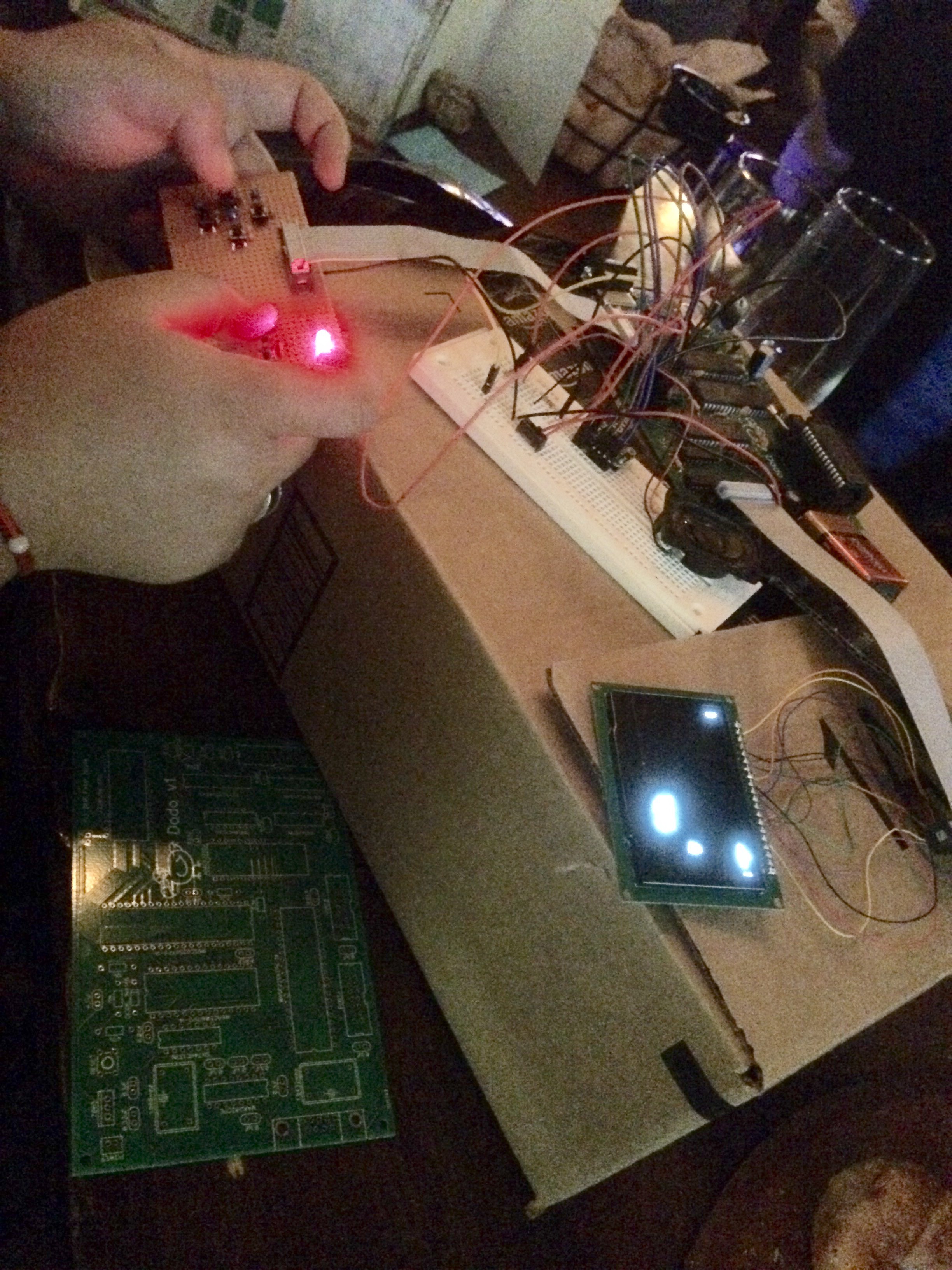
04/01/2016 at 04:23 • 0 commentsThis evening I took Dodo out for the first time. Earlier today I just happened to notice that Hackaday was having a 'show and tell' meetup at a local pub not too far from where I live. I have been wanting to go to one of these meetups but they have always been on Mondays which don't work for me. This was the first one on a Thursday.
The only hiccup with bringing Dodo out is power. So far I have been powering Dodo with a bench supply. I did not want to bring a bench supply to a bar. I scrounged through my things and found a AA pack that holds 4 batteries. I am using a 7805 voltage regulator and it has a 2v dropout which means I really should have 7 volts for a clean 5v output. 4 AA batteries is only 6 volts which wouldn't work. I tried it anyway just to see, and it showed signs of life but didn't really run (as expected.) Unfortunately I didn't have any 9V batteries. I decided to hit up Rite Aid on the way, get a battery, and hope that it would work. Thankfully I did have a 9V harness at least.
I did a bit of research and figured that I probably could run Dodo on a 9V battery for about 5 hours. Dodo uses about 100mA which is above the rating for a 9V battery, but I found some discharge graphs for that current level which showed that it should at least work, but will drain pretty fast.
Anyway, Dodo ended up working and I had a blast showing it off! It was fun to share my enthusiasm for 8-bit hardware and I hope to get out to more of these events. There were some other great projects I got to see as well. A guy has made a power controller box for having battery and solar power for his home, and I also got a great idea to automate refilling the fountain in my front yard. I am sick of refilling that fountain.
![]()
-
FRAM
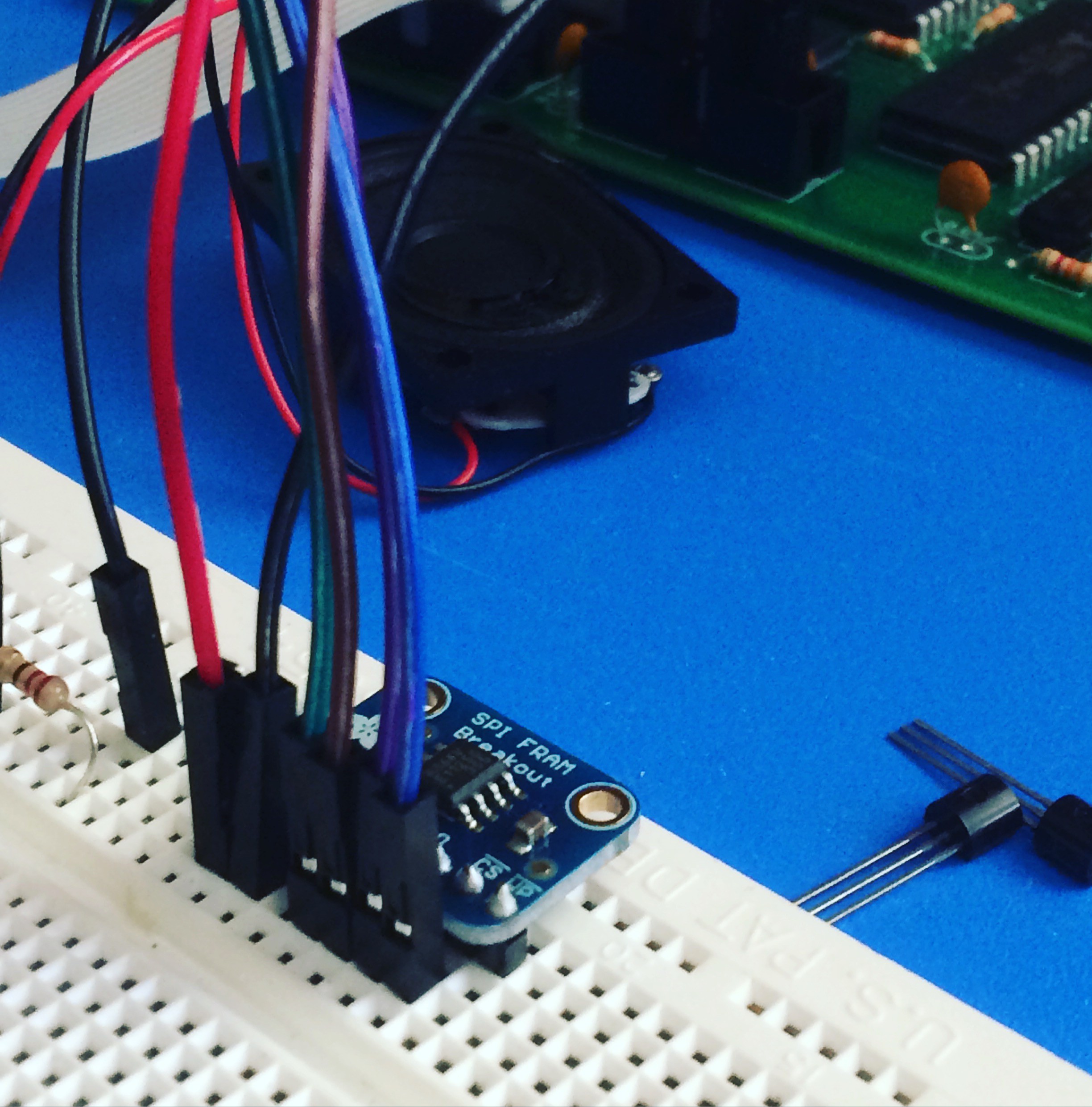
03/22/2016 at 20:26 • 1 commentToday I hooked up an 8k FRAM chip using SPI. I found these FRAM chips on Adafruit. They are pretty sweet being fast, cheap, and most importantly non-volatite. To use SPI I am bit banging Port B on the 6522 VIA. Based on multiple recommendations I have found around the internet, I put the clock on bit 0, and the two serial lines on bits 6 and 7. With this configuration only 10 or so lines of assembly code are needed for the serialization function!
The goal for these FRAM chips is to support swappable game cartridges. I can copy executable code from the chip over SPI and place it in RAM and then execute it. Before this can happen I need to take the IO functions I have and turn them into a BIOS by making sure they are in a predictable place in memory so that they can be called by programs that are compiled independently.
The other option is just to use one for saving high score data.
![]()
-
Moving to Assembly
03/21/2016 at 15:55 • 0 commentsThe sprite drawing functions written in 'C' are just too slow. As an experiment I wrote a draw_sprite function in assembly, that so far only handles the fast case of the y coordinate being a multiple of 8. So far the results are outstanding! In the game 0xDEADBEEF, the alien and cow are always being drawn using the fast case so I was able to switch them over. The new routine saves about 10,000 cycles per frame. With a limit of 50,000 cycles per frame, a 10,000 cycle improvement is huge! The fart utilizes the slow method where lots of shifting needs to happen to get the pixels in the right spot in vmem and is still using the C version. The next step is to rewrite the complex case as well. Below is the fast case written in assembly.
; drawing to #3C00 ;void drawSprite(unsigned char* sprite, unsigned char x, unsigned char y, unsigned char w, unsigned char h, unsigned char flip) _draw_sprite: sta tmp7 ; flip jsr popa sta tmp1 ; h jsr popa sta tmp2 ; w jsr popa sta tmp3 ; y jsr popa sta tmp4 ; x jsr popax sta ptr2 ; sprite stx ptr2+1 lda tmp3 and #$07 ; calculate % sta tmp5 lda tmp3 lsr ; divide by 8 lsr lsr sta tmp6 ; Page lda tmp5 beq @fast jmp @complex ; Fast case @fast: lda #$00 ; pointer to vmem sta ptr1 lda #$3C sta ptr1+1 ; Calculate offset into vmem based on page lda tmp6 ; Load page into a jsr multiply_128 ; a/x = page * 128 adc ptr1 sta ptr1 txa adc ptr1+1 sta ptr1+1 clc lda tmp4 ; add x to ptr1 adc ptr1 sta ptr1 lda #0 adc ptr1+1 sta ptr1+1 ldy tmp2 ; Load width into y, will decrement to 0 dey ; start at w - 1 @next_stripe: ldx #0 lda tmp7 bne @transfer_flip @transfer_next: lda (ptr1), y ora (ptr2), y sta (ptr1), y dey bne @transfer_next lda (ptr1), y ; Last byte ora (ptr2), y sta (ptr1), y jmp @process_done @transfer_flip: tya pha txa tay inx lda (ptr2), y sta tmp8 pla tay lda (ptr1), y ora tmp8 sta (ptr1), y dey bne @transfer_flip txa ; Last byte tay lda (ptr2), y sta tmp8 ldy #0 lda (ptr1), y ora tmp8 sta (ptr1), y @process_done: lda tmp1 sec sbc #8 beq @done ; If h now down to 0, done sta tmp1 clc lda #128 ; Load up next stripe adc ptr1 sta ptr1 lda #0 adc ptr1+1 sta ptr1+1 clc lda tmp2 adc ptr2 sta ptr2 lda #0 adc ptr2+1 sta ptr2+1 ldy tmp2 dey jmp @next_stripe jmp @done @complex: @done: rts ; multiply 8-bit number in a and store results in a/x as 16-bit multiply_128: ldy tmp1 ; cache tmp1 in y ldx #0 ; store 0 in tmp1, a already populated stx tmp1 asl a ; 2 rol tmp1 asl a ; 4 rol tmp1 asl a ; 8 rol tmp1 asl a ; 16 rol tmp1 asl a ; 32 rol tmp1 asl a ; 64 rol tmp1 asl a ; 128 rol tmp1 ldx tmp1 sty tmp1 clc rts -
0xDEADBEEF
03/19/2016 at 17:14 • 3 commentsHere is 0xDEADBEEF, the first game written for Dodo. The concept is that you are an alien trying to abduct cows. The alien's only downfall is that methane is quite toxic. Earn points by abducting cows while avoiding the farts.
I am getting decent performance out of Dodo. The game is running at 20 fps and Dodo is doing all of the pushing of sprites into video memory, and dumping video memory to the display. There is no dedicated graphics hardware. I tweaked the simulator to show me how many CPU cycles are taken per frame and I worked on bringing the number down. When I started it was averaging about 70,000 cycles and I brought it down to 40,000. It needs to be under 50,000 to hit the target 20fps. I have an interrupt firing every 50ms, and at the end of drawing each frame it waits for an interrupt. If the game code is slow and it misses an interrupt, it needs to wait for another one, so when the game was at 70k cycles that meant 10fps.
The game speed drops significantly while abducting and it is entirely due to the line drawing algorithm. I am leaving it the way it is for now because it is sort of a feature, time slows down while abducting. Note that even when the game slows, the music stays correct because it is all interrupt driven.
Here is the game running in my simulator:
-
Simulator
03/13/2016 at 05:51 • 1 commentWith the hardware all working and tested, and a core set of assembly routines written, the time has come to finally write some games. I have actually made some progress on a game but development is quite annoying. I am writing the software on a Mac, but my EEPROM burner only works on my PC. Currently I build on the Mac, upload to dropbox, download on PC, burn chip, and then I can test.
I finally threw in the towel and decided to see what it would take to simulate Dodo for more rapid development. There are a gazillion 6502 emulators out there. I looked over a few of them and found a very simple one written in C that seemed to be a benchmark referenced by other libraries. I ported it to Go, did a quick and dirty simulation of the screen and via chip and I was able to get my software working. I did run into a few hiccups.
1) Typos: I had two bugs related to typos, in one spot I had a copy/paste problem where I missed switching a cpu.X to cpu.Y. I also missed a << 8.
2) 65C02 op codes: I swear that I configured cc65 to output for vanilla 6502, but apparently it is using some newer opcodes that were not in the C emulator I ported, so I needed to add those.
The C Emulator was developed for emulating a Nintendo which used a custom NMOS 6502. Several changes were introduced when they developed the CMOS version.
As I troubleshooted the simulator it was frustrating because it would mostly work, and I had to analyze the generated assembly to try to guess which opcodes had a problem. Eventually I found a test suite written in 6502 assembly that tests all op codes, I was able to find the typo related bugs using the test suite.
Another annoying problem was getting BCD (Binary Coded Decimal) to work. The Nintendo Emulator did not correctly emulate BCD, probably because the Nintendo chip didn't support it at all. The Klaus test suite tests BCD and to be sure I had everything 100% correct I wanted to make sure it was working in case there were other tests I might be failing after the BCD ones. After a bunch of hacking and looking over how other emulators have implemented it, I finally got it working. I doubt I will ever even use it.
The simulator isn't pretty, but for now it gets the job done and writing a game should now be much more painless.
-
Sound
03/03/2016 at 21:25 • 0 commentsAll along I knew I wanted to figure out sound for Dodo because a game system just wouldn't be right without it. I have been going back and forth with lots of different approaches in my mind. Dedicated sound generation chips that mixed both digital and analog circuitry were the norm in the 80s. Perhaps the most famous chip of all was the Commodore 64's SID. Unfortunately, these style of chips are all out of production and I really wanted a design that avoids using old chips that are hard to find. I omitted a sound chip from the PCB so that pretty much left me with a single option, the 6522 VIA.
There are several methods for generating sound on the VIA using the shift register. I could either try for sampled audio or generate square waves at varying frequencies directly. For sampled audio the best I could get would be a 4khz sampling rate with 3-bit resolution, which is really only usable for barely intelligable voice. I opted for option 2 where I use the shift register to generate a square wave.
The Commodore PET lacked a sound chip so anyone wishing for audio did the exact same thing I have done, which is how I learned about the approach. It is documented in the PET programming manual.
For a square wave, either 15, 51, or 85 needs to be loaded into the shift register. The binary values are 0001111, 00110011, and 01010101. You can see from their bit patterns how they each result in a square wave. In VIA SR mode 4, the shift register is free-running and is based on the T2 clock, which is exactly what I want to get the sound going. Thankfully, the PET engineers did all the math to figure out exactly what values need to be loaded into the T2 clock to generate specific notes. This is straight from the PET manual:
       octave=15     octave=51     octave=85
  Note  Oct.0 Oct.1 ! Oct.1 Oct.2 ! Oct.2 Oct.3
  Freq  ------------+-------------+--------------
   B     251   125  !  251   125  !  251   125
   C     238   118  !  238   118  !  238   118
   C#    224   110  !  224   110  !  224   110
   D     210   104  !  210   104  !  210   104
   D#    199    99  !  199    99  !  199    99
   E     188    93  !  188    93  !  188    93
   F     177    88  !  177    88  !  177    88
   F#    168    83  !  168    83  !  168    83
   G     158    78  !  158    78  !  158    78
   G#    149    74  !  149    74  !  149    74
   A     140    69  !  140    69  !  140    69
   A#    133    65  !  133    65  !  133    65
For amplifying a square wave not much is needed. I found an old NPN transistor (type bc170c) which I wired up to a 1w 8ohm speaker.
For the initial test I implemented some code that played the intro to Fur Elise!
            ...

            lda ACR
            and #%01111111
            ora #%01000000
            ora #%00010000      ; For sound (T2 free running)
            sta ACR
            lda #%11000000
            sta IER

            ; Music
            lda #15             ; Low octave
            sta SR
            ldx #0
@next_note:
            lda music,x
            beq @done
            sta T2CL
            inx
            lda #250
            jsr _delay_ms
            jmp @next_note
@done:
            lda #0
            sta T2CL
            rts

music:              .byte 93, 99, 93, 99, 93, 125, 104, 118, 140, 0
This Shift Register based sound generation will work well for my system because the CPU usage should be relatively low. Because the output is free-running, it will keep generating the same sound until instructed to do something different. I don't have to oscillate a pin directly myself to generate the square waves.
I can just have my interrupt that is already firing do a little extra work to orchestrate which sound to play next, should work well!
-
Sprites and Game Loop
03/01/2016 at 22:21 • 0 commentsThe software is coming along. The screen is now rendering at a consistent FPS based on the timer interrupt. The timer counts 50,000 clock cycles at a time, which at a 1mhz CPU comes out to 20 fps. The LED flashing in the video is flashing once per frame. Instead of running all game code in the IRQ handler, I instead added a wait for irq call. The IRQ handler simply sets a flag when interrupted, and the wait call spins until that flag is set. This way a minimal amount of code runs in the interrupt handler. The main game loop just calls wait each cycle.
I also figure this is best because cc65 triggers BRK whenever the runtime encounters a fault, and BRK causes a software interrupt to fire. If the majority of my code was actually in the interrupt handler, then I would never be able to react to or even detect a BRK properly.
I also now have sprite drawing fully working. Previously my sprite drawing routine was only working if the y offset of the sprite was on a page boundary of 0, 8, 16, etc... The routine is a bit complicated because it is optimized to move as many bits at a time as possibly straight into video memory, rather than the naive approach of calling getpixel / setpixel. Here is the routine, with really ugly variable names:
void drawSprite(unsigned char* sprite, unsigned char x, unsigned char y, unsigned char w, unsigned char h) { unsigned char p = y/8; unsigned char yoff = y%8; unsigned char yoff_inv = 8-yoff; unsigned char i = 0; unsigned char il = 0; unsigned char yp = 0; unsigned char last = 0; unsigned char* vmem = VIDEO_MEM; // + _char_x + (p*128); for (i = 0; i < p; ++i) { vmem += 128; } vmem += x; i = 0; for (yp = 0; yp < h; yp += 8) { il += w; last = 0; for (; i < il; ++i) { if (yoff > 0 && yp > 0) { last = sprite[i - w] >> yoff_inv; } *vmem |= (sprite[i] << yoff) + last; vmem++; } vmem += (128 - w); } // Go through last set of sprite data becasue it spills over into next page of VMEM if (yoff > 0) { i -= w; for (; i < il; ++i) { *vmem |= (sprite[i] >> yoff_inv); ++vmem; } } } -
Gamepad
02/29/2016 at 21:50 • 2 comments![]()
A game system is not much fun without a gamepad so I prototyped up a quick one. I am now pretty close to being able to implement a game. Each button has its own little debounce circuit. The output of the buttons are tied high through a resistor, and are shorted when the switch closes. There is also a 0.1uF capacitor across each button. I am hoping the buttons work well enough as is without having to debounce in software.
I did an initial test of modifying my interrupt routine to test if the 'UP' button is depressed and if so to illuminate the LED. It worked!
-
Sprites
02/28/2016 at 22:34 • 0 commentsFor the first time I now have something "gamelike" running on Dodo! I now have software to render a game background and a sprite. The walking cycle on this character is a bit rough, and could use several more frames, but in concept it is working. I have a sleep of 255ms per frame so I can slow it down to see what is happening. Funny that I finally have something going too quick on this slow little 1mhz machine. Furthermore, there is still a lot of room for optimization with what I have implemented thus far. I am now confident I will be able to implement a playable game on this thing.
The other good news is that I finally got around to verifying that interrupts are working. I successfully configured the 6522 to use one of timers to fire a regular interrupt. This was the one item I designed on the PCB without having ever tested it. I also have the 6551 wired for interrupt as well but I am not sure I will ever use it. The timer interrupt is important because I will use it to pump my game loop to ensure that it runs at a consistent FPS.
Interrupt lines on for these series of chips need to be carefully designed. The old style IRQ outputs are all open drain on the original chips so that they can be wired together. The newer chips with the 'C' in the middle are no longer open drain. I have a mix, my 65C22 is not open drain but my old 6551 ACIA is. I fed both interrupts into an AND gate and there is a pullup for the ACIA.
-
Game of Life
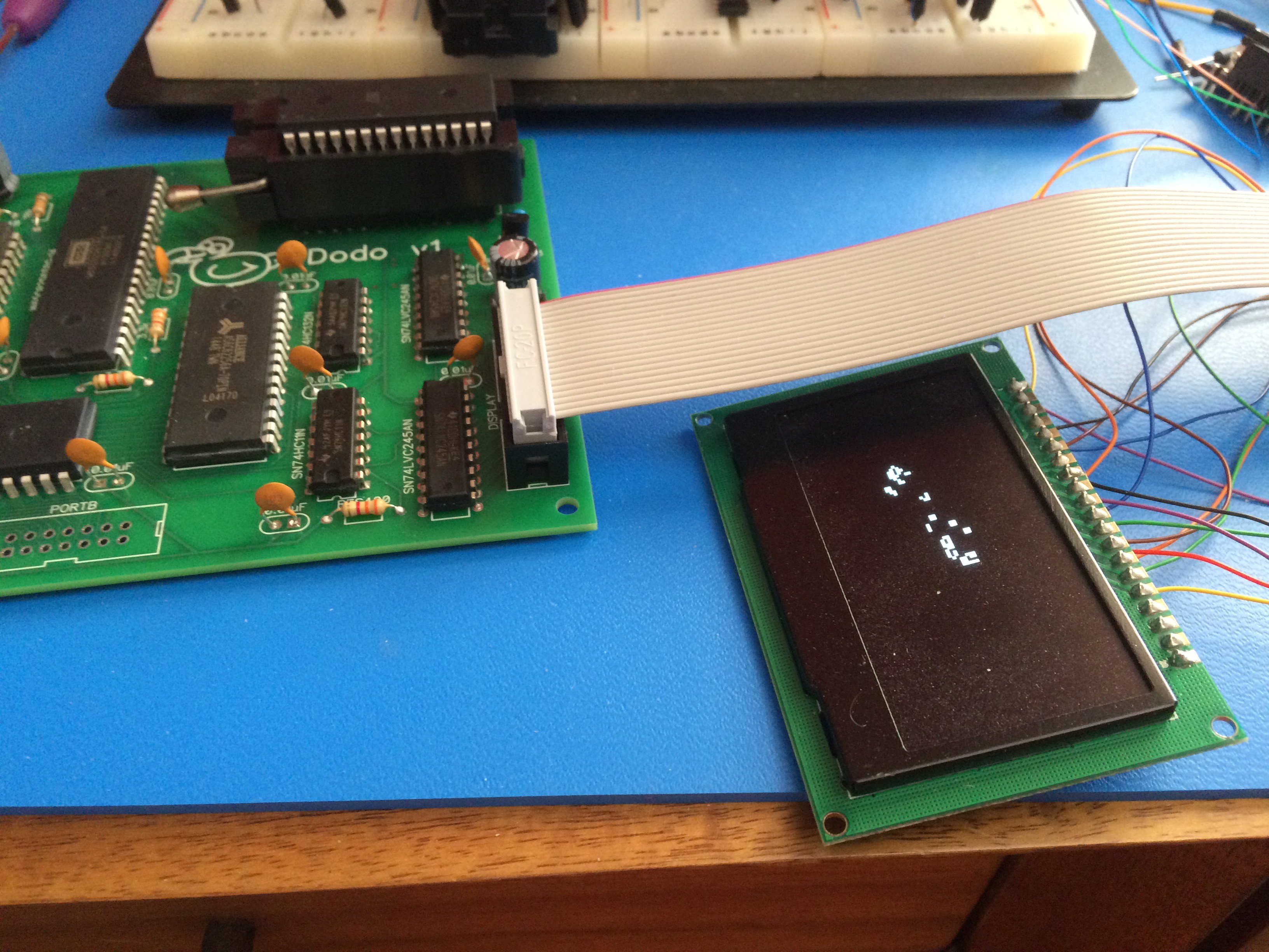
02/20/2016 at 20:28 • 0 commentsAs a next test I thought it would be interesting to implement the famous "Game of Life" cellular division simulation. I wrote it in 'C' and it didn't work at first, or so I thought. Well, it does work, but it renders about a frame per minute! My code is completely unoptimized and plus there is overhead from using C.
Each frame involves reading 73,728 pixels (128*64*9), and each read involves a multiplication, addition, modulus, many shifts, and an and. I could make it a bit faster I am sure, but this application is a bit tough on my little 6502!
The good news is that I have been letting it run for hours and it just keeps chugging along!
![]()