 Yann Guidon / YGDES
As I found in Testing the Flip-Flop, my smaller generalised Flip-Flop is not performing fast enough. It seems to be limited around a few KHz, which is ok for the Johnson counters but not for the 32KHz divider. A few hypothesises are being considered :
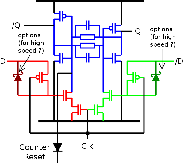
- Use a couple of P-FET to fast-purge the N's gate (if all the following ideas fail)
- Alternatively, a Schottky diode could work and reduce the parts count (no need of a complementary clock input)
- A couple of 100p/1nF capacitors across the feedback resistors could do wonders too.
- Maybe the feedback resistors are too weak. A lower resistance is not a problem since the current passes only to charge the gate, during the time it takes to go the whole feedback loop. It could be that going from 1M or 100K to 10K or 1K Ohm would work better. This would save capacitors.
- Maybe the clock enable network has an influence too, if it's connected to ground, or between the FF and the charge pumps.
Here are some possibilities:
Now that I have the 32KHz source, I can make better measurements :-)
After I compare the position of the clock enable, the easiest would be to see the influence of the resistor value, then add the cap, then try the Schottky, and finally the P-FET. So let's go...
Result:
I used the 32KHz generator for all the tests.
- Capacitor: FAIL. This gives really weird waveforms, no frequency division. I tried 820p but maybe the resistor was not the right value.
- Diode : Yeah ! I tried a 1N60 and it worked great. The resistor value is still an issue though.
- Resistance : I initially tried 100K but... hmmm...
I then tried 200K, 33K and 10K:
200K:![]() 33K:
33K:![]() 10K:
10K:![]()
 33K:
33K: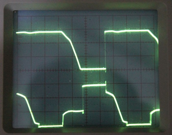 10K:
10K: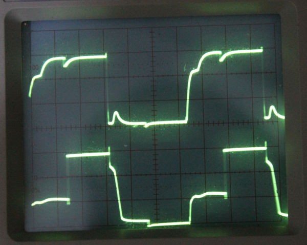
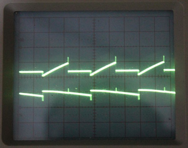
(Legend:
- top trace : voltage at Q
- bottom trace : voltage at the gate of the N-FET charge pump
)
Conclusion :
- I'll stick to 10K everywhere. It's a compromise because many 10TFF will have a set/reset input and all those shorted wires will draw a significant current, this would drain the battery and the supply voltage could be affected by a spike/drop too.
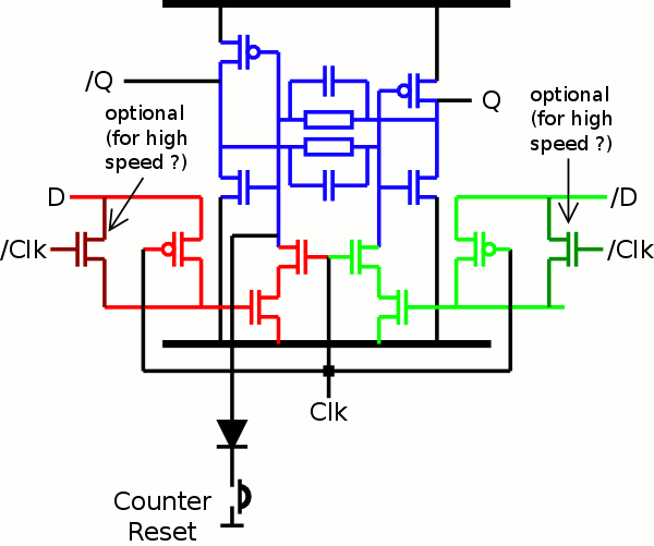
- The Germanium diode is cool and will be selectively added in the fastest circuits (down to maybe 4KHz). It can be replaced by a Schottky diode as well but that's what I had in sight :-)
So I'm settling with this circuit:
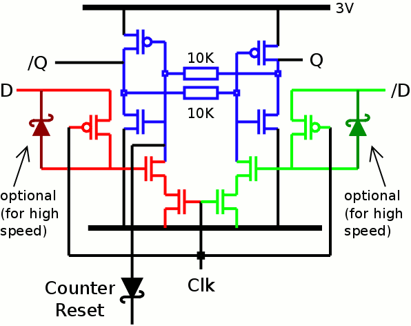
I didn't try a different topology with the CLK in the middile instead of low-side...
Discussions
Become a Hackaday.io Member
Create an account to leave a comment. Already have an account? Log In.
Nice.... For $20-30 it would be worth to make a few Pi-crystals just for the fun of it. Good to know that VGA's are as accommodating frequency-wise as an old TV set.
Fsck! I hate the commenting system here. Is sucks b*lls....
Are you sure? yes | no
I think I have to build a ovenized LC-oscillator and accept the non-perfect edges. Maybe it would be possible to find an old big crystal slightly faster than pi and then try to bring it down by drawing with a sharpie on the crystal itself.... But finding someting today that is close enough without a special order is probably impossible.
Are you sure? yes | no
Come on ! Pi is everywhere :-)
Are you sure? yes | no
I got a 3.12MHz crystal on my SP0256 speech synthesizer board. Some oscillators these days have OTP PLL inside and you get get them customized at the rep's.
Are you sure? yes | no
What is the purpose of the schottkys? They are not acting as Baker clamps as in BJTs to reduce the Miller effect I guess...
Are you sure? yes | no
Well, the P-FET "charges" the N-FET's gate.
The P-FET's intrinsic diode is too... lazy to empty the N-FET's gate capacitance fast enough. I tried with 1N60 (0.27V drop) so when the respective data line goes low, it clears the gate. In ultrafast designs (ICs) a pass-gate (N-FET and P-FET without intrinsic diode) would be used instead but... geeks wanna have fun and I'm happy I found a use for those 1N60s :-)
Are you sure? yes | no
Please make me a ring counter (a real ring counter, not a Johnson) that can be toggled at 3.146875 MHz and I can build by CHIP-8 compatible (64x32 pixels) discrete VGA video card ... :-)
Are you sure? yes | no
huh .... ?
with MOSFET ?
I thought you were more into NPN and higher power draw ;-)
Are you sure? yes | no
Hm... yea, I think that mosfets might be out of that range... But that doesn't mean that you can make one with bjt's for me :)
Are you sure? yes | no
depends on your budgetS (room/size, power, time, price...)
After all, people did computers with germanium transistors 60 years ago :-D
Are you sure? yes | no
Class E Tesla coils just when you think MOSFET don't run that fast. :) http://www.vk2zay.net/article/253
Are you sure? yes | no
K.C. : I'm feeling dirty... I'm buying old Ge PNP transistors just to use them as common cathode diode pairs... and to look cool while people wonder what this does.
Are you sure? yes | no
Guitar amp effects guys probably inflated that market. I got a small bag of Ge transistors and various vintage chips.
Are you sure? yes | no
Should aim for 3.1415926MHz?
Are you sure? yes | no
I wonder if that's close enough to make a VGA monitor happy...
Targeting a 640x480 video with the orginal 25.175Mhz pixel clock.
8 pixel-times s front porch
96 pixel-times horizontal sync
40 pixel-times back porch
8 pixel-times left border
640 pixel-times active video
8 pixel-times right border
------------------------------------
Total 800 pixel-times
If I divide the 25Mhz pixel clock with 8 I get 3.146875Mhz and a total of 100 "pixel-times". And then I have 80 fat pixels horizontally and can use 64 of them for the graphics.
If would definitely be cool if it could run on Pi-Mhz.
Are you sure? yes | no
First you have to find the Xtal that resonates at Pi MHz.
For the rest, you can trust K.C. since he did some neat VGA timing magic lately :-)
Are you sure? yes | no
Ceramic resonators have a lower Q factor, you might be able to "pull" it toward Pi MHz ?
Are you sure? yes | no
http://hackaday.com/2010/05/10/hack-your-crystals-frequency/
>2. You can custom order the frequency you want. There are number of manufacturers who'll do this for you. But it'll cost maybe US$15 to US$35 PER custom valued crystal.
I was supposed to run the dot clock and all my timing off 25.175MHz, but I use 25MHz because it is 1/3 cost (Ethernet vs something few uses). Just for the hack of it, I tried 24MHz earlier today and that worked too. There is quite a bit of play on my LCD monitor.
Misprogrammed the PLL by a factor of 2x i.e. running at 96MHz core speed, saw the sync pulse on the scope at 60kHz. At least part of the code actually execute to starts the timer. Didn't bother to start the debugger.
Are you sure? yes | no