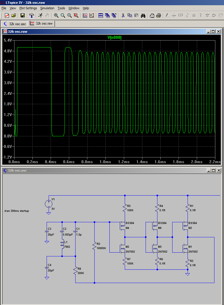
This is the next log after the discussion at https://hackaday.io/project/9376-yet-another-discrete-clock/log/32117-crystal-oscillator-with-complementary-mosfets. See also the following log Crystal Oscillator (Germanium Edition)
Making a quartz crystal oscillate at all is still some kind of black art for me and I still need a DS32KHZ integrated chip to work reliably. Georges W. Pierce nailed the secrets a century ago and a famous topology is named after him. But the related wikipedia article is, IMHO, not complete, I would like to add a few things.
To be fair, the article is OK and contains some important aspects of the design:
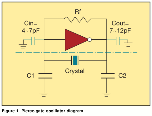
- the pi network band-pass filter, which provides a 180 degree phase shift, is essential. The crystal alone, or the inverter, is not enough and the 2×NPN oscillator is one notable exception, not a rule: the Pierce oscillator needs these two capacitors at the legs.
- The biasing resistor is well explained
- The isolation resistor is indeed needed to protect from high-energy drivers
But I believe that some things have not been emphasised enough. The article mention that we "assume the inverter is ideal, with infinite input impedance and zero output impedance.". I think that my failures are due to not fulfilling all the requirements at once, and I start to believe that the gain of my previous circuits has been pretty bad. Even the 2-transistors circuit takes many seconds to reach its nomilal amplitude.
Meanwhile, most "discrete" circuits I see employ a single inverter gate, which has a very high gain. However I still try to minimize the number of MOSFETs and I end up with a poor gain. Input impedance is good but the circuit is at most a voltage follower centered around Vcc/2. The Ge transistors I've tried have a low current gain (150) and fail to start up. Should I try a Darlington ?
Oh, more information overload : http://www.crystekcrystals.com/crystal/appnotes/PierceGateLoadCap.pdf
"The C1 and C2 values also affect the gain of the oscillator. The lower the values, higher the gain. Likewise, C2 /C1 ratio also affects gain. To increase the gain, make C1 smaller than C2 ."

With very high gain comes non-linearity. I am wondering if hysteresis helps.
It is clearly not necessary since it's not part of the oscillation conditions (phase, amplification) and the 2-BJT oscillator it not very-high-gain and seems pretty linear. But the startup is so slow !
OTOH @K.C. Lee's oscillator starts almost immediately because the very high gain forces the output to be in one state or another, not a continuum.
 I start to believe I am foolish to try to reduce the number of MOSFETs of this design. I have no good result with only 2 MOSFFET.
But I would modify K.C.'s oscillator by changing R1 or R2 to 10K or more, which would reduce "metastability" by lifting/shifting the active level of the last stage, effectively adding a little bit of hysteresis...
Another question is : why are 32768Hz quartz harder/more delicate to drive than MHz+ quartz ? Is the tuning fork structure inherently harder to drive than the sheet/disk cut ?
 Yann Guidon / YGDES
Discussions
Become a Hackaday.io Member
Create an account to leave a comment. Already have an account? Log In.