-
Starting on the Mark IV version...
06/01/2016 at 02:02 • 0 commentsPreliminary source code is up at github - https://github.com/alphacharlie/ESPx-Chronograph
Also - finally Starting on the Mark IV version. I've got the timer code working well on the ESP8266 and have recently received some new BPW-34 photodoides. The Mark IV design is an open trap design. Since we're using the ESP8266 which has wifi, I'm also building a web interface into the chronometer. This will allow display of multiple readings and averaging of readings and settings menu.
The first open-trap design will experiment with translucent plastic sheet to diffuse natural sunlight and with LEDs to illuminate the trap area actively to see which works better as a trigger.
-
Video Demo of Prototype
02/13/2016 at 20:57 • 0 commentsHere's short demo of the prototype:
The newest version of this project uses the ESP8266. This gives it an order of magnitude boost in precision over the previous version. (The first prototype used an Arduino at 16MHz. But due to the limitations of the 328P was not able to take full advantage of it. The ESP8266 has a CCOUNT register. This is an unsigned 32 bit int that always has a running tally of the clock cycle count at the full 80MHz of the ESP8266. fps speed is then determined by taking the clock cycle rate and dividing it by the difference between the first and second measured CCOUNT:
fps = 80000000 / ( CCOUNT_2 - CCOUNT_1 )
Since the max value of the CCOUNT register is 4294967291 and it increments at 80 MHz, there is a small (1 in 50000 or so) chance that the CCOUNT register will have reset between the first and second measurement. To handle this we check to see if CCOUNT_2 < CCOUNT_1. If it is we can still get fps by doing -
fps = 80000000 / ( ( 4294967291 - CCOUNT_1) + CCOUNT_2 )
Code will go up on Github in the next day or two. Until then...
-
Mark II Detector
02/08/2016 at 23:00 • 0 commentsShown here is the Mark II detector. It is smaller in diameter, shorter and more sensitive than the first prototype.
![]()
This detector is suitable for airgun use and clamps onto the end of the barrel. Each gate circuit has a potentiometer for sensitivity and uses a transistor to amplify the signal from the optical trigger and an SCR to trigger the digital pin(s) of the Arduino.
The length between the first and second optical gate is 12" (1 foot). This makes the FPS calculation exceedingly simple:
FPS = 1000000 / microseconds
To get meters per second we simply multiply our FPS by 0.3048.
MPS = FPS * 0.3048
I should have the source code up on Github in a few days so stay tuned!
-
Mark I Detector
02/01/2016 at 20:39 • 0 comments![]()
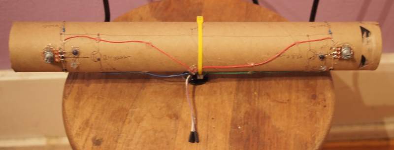
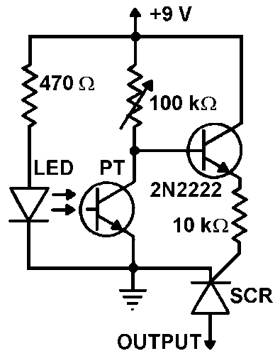
Above is a picture of the first detector prototype. It used a 3" ID packing tube. The sensor tube consisted of 2 emitter-detector pairs at a fixed distance. Each detector output is amplified by a bipolar transistor and the output is used to trigger an SCR.
![]()
The circuit used (schematic above) was one I found on this thread - http://www.electro-tech-online.com/threads/stripboard-layout.31418/ however I hadd to adjust component values to compensate for the supply being 5VDC. I used a 330 ohm resistor instead of 470, a 20K pot instead of 100K and a 3.3K instead of the 10K resistor. (The tube contains two trigger circuits.)
The circuit worked well but triggering was inconsistent due to the sensors having a fairly narrow sensitivity. (perhaps 60 degrees?) The mark II prototype uses a narrower tube and shorter distance between sensors to get more consistent triggering.
If you have problems getting it to trigger-
- use a cell-phone camera to check your emitter. (the camera can see the IR)
- to set the sensitivity reduce the potentiometer resistance until the circuit triggers, then back it off a bit.
- too bright of an emitter will prevent the triggering for small/fast projectiles. So if you have problems, try increasing the value of the current limiting resistor to reduce the emitter brightness.
DIY Ballistic Chronograph
A simple DIY ballistic chronograph using IR emitter/phototransistor triggering, an ESP8266 and an I2c LCD
 Alpha Charlie


