 Roman
Roman-
1Step 1
![]()
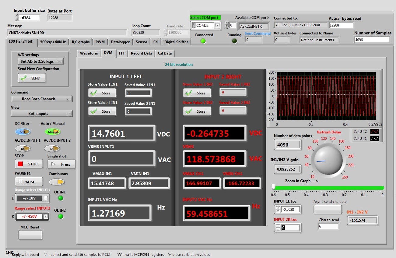
The following image is a snapshot of running 24 bit DMM UI page. The display gets updated every 1.2 seconds, it takes approximately 1.2 sec to collect all data samples. Left Input is connected to DC supply, Right Input connected to an AC line. AC needs to be calibrated.
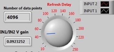
![]() Refresh delay in milliseconds. It is the delay time between
reads. The image displays 41 milliseconds delay. Number of data points shows
how many values have been received (each value is 24 bit).
Refresh delay in milliseconds. It is the delay time between
reads. The image displays 41 milliseconds delay. Number of data points shows
how many values have been received (each value is 24 bit).
![]()
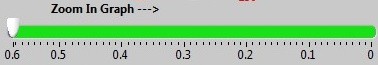
Zoom in to the displayed waveform. Expands the waveform in time axis.
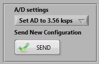
![]() Send sampling rate to ADC. Currently sampling rate can be
set to 3560 samples/second or 57000 samples/second.
Send sampling rate to ADC. Currently sampling rate can be
set to 3560 samples/second or 57000 samples/second.
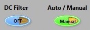
![]() DC filter helps to fight noise. Auto / Manual sets how the
unit will set a voltage range. Auto will make the unit test applied voltage and
select an appropriate voltage range. Manual will allow a user to set the
voltage range.
DC filter helps to fight noise. Auto / Manual sets how the
unit will set a voltage range. Auto will make the unit test applied voltage and
select an appropriate voltage range. Manual will allow a user to set the
voltage range.
![]()
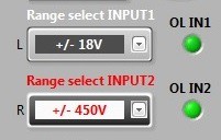
Manually set voltage ranges: +/0.6V, +/-18V, +/-110V, +/-450V
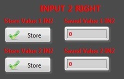
![]() If you need to store current reading, just click on “Store”
If you need to store current reading, just click on “Store”
![]() Input 2 display window. Input 2 shows a -0.26V DC offset
measured on 118.57 VAC line.
Input 2 display window. Input 2 shows a -0.26V DC offset
measured on 118.57 VAC line.All LabVIEW files you can be downloaded in zip format from the LabVIEW link. Sorry for the mess in my files. I am trying to organize my C source code files, but it might take a while.
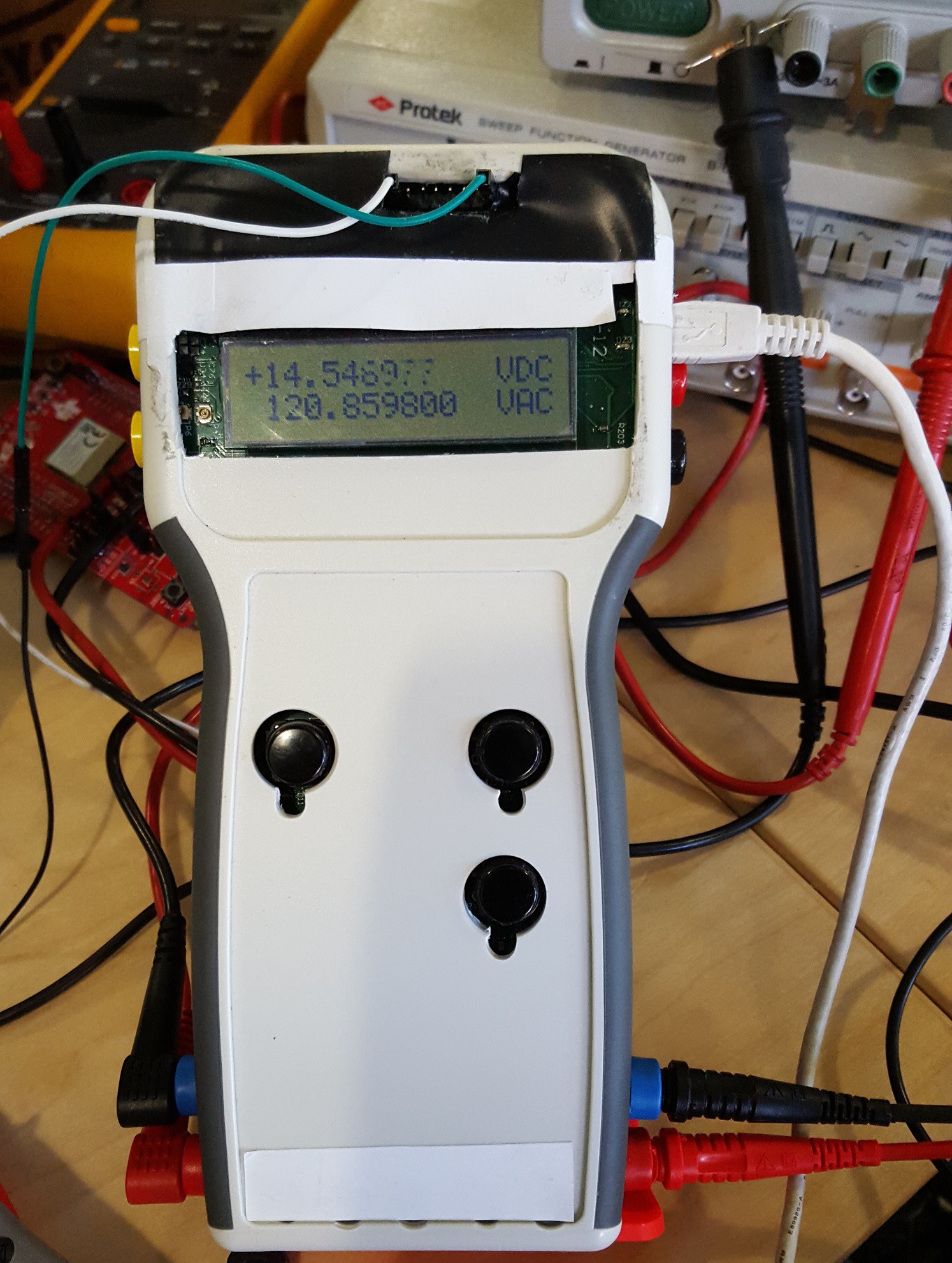
Multimeter +
Dual input 24 bit Multimeter with USB interface, single channel 10 bit USB oscilloscope, PWM out, 2 Ch Data-logger, R, C, Digital sniffer.
 Refresh delay in milliseconds. It is the delay time between
reads. The image displays 41 milliseconds delay. Number of data points shows
how many values have been received (each value is 24 bit).
Refresh delay in milliseconds. It is the delay time between
reads. The image displays 41 milliseconds delay. Number of data points shows
how many values have been received (each value is 24 bit).
 Send sampling rate to ADC. Currently sampling rate can be
set to 3560 samples/second or 57000 samples/second.
Send sampling rate to ADC. Currently sampling rate can be
set to 3560 samples/second or 57000 samples/second.
 DC filter helps to fight noise. Auto / Manual sets how the
unit will set a voltage range. Auto will make the unit test applied voltage and
select an appropriate voltage range. Manual will allow a user to set the
voltage range.
DC filter helps to fight noise. Auto / Manual sets how the
unit will set a voltage range. Auto will make the unit test applied voltage and
select an appropriate voltage range. Manual will allow a user to set the
voltage range.
 If you need to store current reading, just click on “Store”
 Input 2 display window. Input 2 shows a -0.26V DC offset
measured on 118.57 VAC line.
Input 2 display window. Input 2 shows a -0.26V DC offset
measured on 118.57 VAC line.
Discussions
Become a Hackaday.io Member
Create an account to leave a comment. Already have an account? Log In.