Roman
Roman-
Digital Sniffer
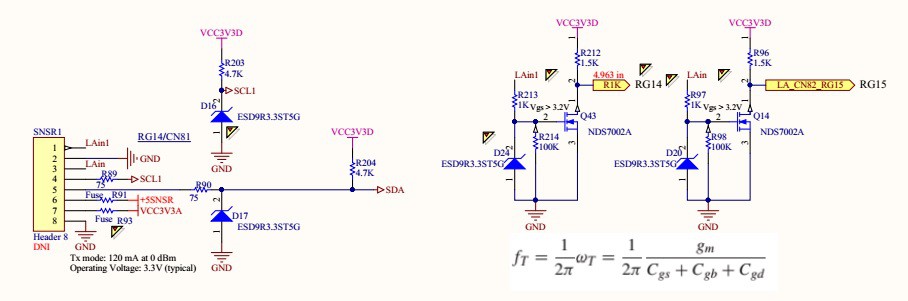
07/02/2016 at 15:33 • 0 commentsI am currently working on the Digital Sniffer. The following image show the interface schematics.
Expansion Port:
Signal is applied to Pin 1 of the SNSR1 connector. Pin 2 is the ground return. Signal is buffered and inverted by the Q43, NDS7002, MOSFET. D24 is used to protect Q43 from overvoltage condition. Passing the buffer, the signal is applied to PIN 93 MCU. RG14 is an interrupt pin CN81. CN81 is the Input Change Notification pin. The input change notification function of the I/O ports allows the PIC24FJ256GA110 family of devices to generate interrupt requests to the processor in response to a change of state on selected input pins. This feature is capable of detecting input change of states even in Sleep mode, when the clocks are disabled.![]()
MCU:
![]()
Interrupt is initialized inside init_logic_analyzer() function.
PIC24FJ256GA110:
// <editor-fold defaultstate="collapsed" desc="Initialize CN82 on RG15 Interrupt">
    CNEN6bits.CN82IE    	= 1; // Enable interrupt on CN82 RG15 2N7002
    CNPD6bits.CN82PDE   = 0;    	// Pull down disable
    CNPU6bits.CN82PUE   = 0;    	// Pull up disable
    CNEN6bits.CN81IE    	= 1;    	// Enable interrupt on CN81 RG14
    CNPD6bits.CN81PDE   = 0;    	// Pull down disable
    CNPU6bits.CN81PUE   = 0;    	// Pull up disable
    IEC1bits.CNIE       	= 1;    	// Enable interrupt on pin change
    IFS1bits.CNIF       	= 0;    	// Clear the flag
    IPC4bits.CNIP       	= 4;    	// Interrupt priority 4
    // </editor-fold>
    flags = 13;         // Indicates that the Logic Analyzer has been initialized.
    return;
}
Once interrupt is initialized it is ready to read input fromSNSR1 PIN1.
OSCILLATOR data:
Primary oscillator = 7.3728MHZ
Phase Lock Loop:
XTPLL = 4 x PLL = 7.3728MHZ x 4 = 29.4912MHz
FCY = XTPLL/2 = 14.7456MHz. FCY is defined as XTPLL/2
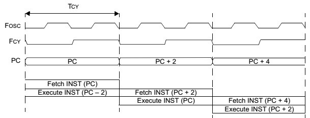
The processor clock source is divided by two to produce the internal instruction
cycle clock, FCY.
![]()
TCY = 1 / FCY = 1 / 14.7456MHz = 0.067817 us
INTERRUPT PROCESSING TIMING
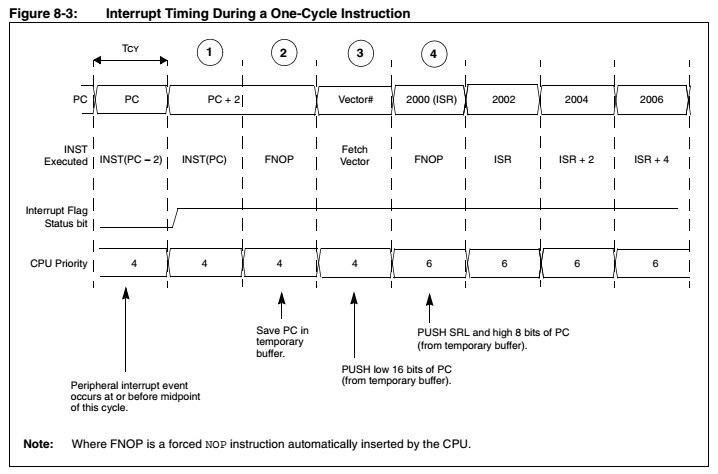
Figure 8-3 shows the sequence of events when a peripheral interrupt is asserted during a
one-cycle instruction. The interrupt process takes four instruction cycles. Each cycle is numbered
in Figure 8-3 for reference.![]()
The interrupt process takes four instruction cycles.
TINTERRUPT = TCY * 4 = 0.067817 * 4 = 0.271 us
FMAX-INTERRUPT = 1 / 0.271 us = 3.69 MHz
Each instruction has Fetch and Execute parts. It takes TCY
for each instruction (oscillator).
It looks like I have 16 - 17 instructions in the ISR, then
T = TINTERRUPT + 17 * 0.067817 = 1.017 us + 0.271 us = 1.363us
Max input data-stream frequency is:
FDATA = 1 / 1.363 = 0.7 MHz
I have tested Multimeter+ with max frequency of 500 kHz. Its kind of slow for a logic Analyzer, but for a regular multimeter it adds value.
The following code triggers on every CIN interrupt and shifts in a bit of data.
// Global volatile WORD_VAL timer[8]; extern volatile unsigned int TMR1 __attribute__((__sfr__)); volatile DWORD_VAL NmbrOfBits; volatile WORD_VAL TimeBase; volatile unsigned long ints; volatile unsigned char mask_l; void __attribute__((interrupt, no_auto_psv)) _CNInterrupt(void){ // Time interval = Number of counts * Time of one count timer[0].Val = (WORD)(TMR1 * 68); NmbrOfBits.Val = timer[0].Val / TimeBase.Val; TMR1 = 0; if (LAcntr < 2048){ if (NmbrOfBits.Val == 0){ goto skip; // Skip all } else if (NmbrOfBits.Val == 1){ // 7 bits left // Input is inverted !_RG14 is actually _RG14. // If RG15 is low set current bit to zero with mask_h = 0xFE if (_RG14) { voltage_msb[LAcntr] = mask_h; // mask_h is initialized to 0b1111 1110 } else { // If RG15 is high set current bit to one with mask_h = 0x01 voltage_msb[LAcntr] = ~mask_h; // ~mask_h = 0b0000 0001 } } else if (NmbrOfBits.Val == 2){ // <editor-fold defaultstate="collapsed" desc="2 bit"> mask_h = mask_h << 1; // 1111 1110 << 1 = 1111 1100 // Input is inverted !_RG14 is actually _RG14. // If RG15 is low set current bit to zero with mask_h = 0x0b11111100 if (_RG14) { voltage_msb[LAcntr] = mask_h; // mask_h << 1 = 0b1111 1100 } else { // If RG15 is high set current bit to one with mask_h = 0x01 voltage_msb[LAcntr] = ~mask_h; // ~mask_h << 1 = 0b0000 0011 } // </editor-fold> } else if (NmbrOfBits.Val == 3){ // <editor-fold defaultstate="collapsed" desc="3 bit"> mask_h = mask_h << 2; // 1111 1110 << 2 = 1111 1000 if (_RG14) { // Input is inverted !_RG14 is actually _RG14. If RG14 is low set current bit to zero with mask_h = 0x0b11111100 voltage_msb[LAcntr] = mask_h; // mask_h << 2 = 0b1111 1000 } else { // If RG15 is high set current bit to one with mask_h = 0x01 voltage_msb[LAcntr] = ~mask_h; // ~mask_h << 2 = 0b0000 0111 } // </editor-fold> } else if (NmbrOfBits.Val == 4){ // 0000 0001 << 4 = 0001 0000 // <editor-fold defaultstate="collapsed" desc="4 bit"> mask_h = mask_h << 3; // 1111 1110 << 3 = 1111 0000 if (_RG14) { // Input is inverted !_RG14 is actually _RG14. If RG14 is low set current bit to zero with mask_h = 0x0b11111100 voltage_msb[LAcntr] = mask_h; // mask_h << 3 = 0b1111 0000 } else { // If RG15 is high set current bit to one with mask_h = 0x01 voltage_msb[LAcntr] = ~mask_h; // ~mask_h << 3 = 0b0000 1111 } // </editor-fold> } else if (NmbrOfBits.Val == 5){ // 0000 0001 << 5 = 0010 0000 // <editor-fold defaultstate="collapsed" desc="5 bit"> mask_h = mask_h << 4; // 1111 1110 << 4 = 1110 0000 if (_RG14) { // Input is inverted !_RG14 is actually _RG14. If RG14 is low set current bit to zero with mask_h = 0x0b11111100 voltage_msb[LAcntr] = mask_h; // LAcntr is incremented when byte of data has been shifted } else { // If RG14 is high set current bit to one with mask_h = 0x01 voltage_msb[LAcntr] = ~mask_h; // Turn on bit zero (mask_l = 0x01). If the first bit is one save one in voltage_msb[0] bit 0 } // </editor-fold> } else if (NmbrOfBits.Val == 6){ // 0000 0001 << 6 = 0100 0000 // <editor-fold defaultstate="collapsed" desc="6 bit"> mask_h = mask_h << 5; // 1111 1110 << 5 = 1100 0000 if (_RG14) { // If RG15 is low set current bit to zero with mask_h = 0x0b11111100 voltage_msb[LAcntr] = mask_h; // LAcntr is incremented when byte of data has been shifted } else { // If RG15 is high set current bit to one with mask_h = 0x01 voltage_msb[LAcntr] = ~mask_h; // Turn on bit zero (mask_l = 0x01). If the first bit is one save one in voltage_msb[0] bit 0 } // </editor-fold> } else if (NmbrOfBits.Val == 7){ // 0000 0001 << 7 = 1000 0000 // <editor-fold defaultstate="collapsed" desc="7 bit"> mask_h = mask_h << 6; // 1111 1110 << 6 = 1000 0000 if (_RG14) { // If RG15 is low set current bit to zero with mask_h = 0x0b11111100 voltage_msb[LAcntr] = mask_h; // LAcntr is incremented when byte of data has been shifted } else { // If RG15 is high set current bit to one with mask_h = 0x01 voltage_msb[LAcntr] = ~mask_h; // Turn on bit zero (mask_l = 0x01). If the first bit is one save one in voltage_msb[0] bit 0 } // </editor-fold> } else if (NmbrOfBits.Val == 8){ // 0000 0001 << 7 = 0000 0000 // <editor-fold defaultstate="collapsed" desc="8 bit"> mask_h = mask_h << 7; // 1111 1110 << 7 = 0000 0000 //mask_l = mask_l << 8; if (_RG14) { // If RG15 is low set current bit to zero with mask_h = 0x0b11111100 voltage_msb[LAcntr] = mask_h; // LAcntr is incremented when byte of data has been shifted } else { // If RG15 is high set current bit to one with mask_h = 0x01 voltage_msb[LAcntr] = ~mask_h; //Turn on bit zero (mask_l = 0x01). If the first bit is one save one in voltage_msb[0] bit 0 } // </editor-fold> } else { // If time lapse is more then 8 bit //mask_l = mask_l << 8; // Indicate full byte has been received mask_h = mask_h << 7; // This will indicate that a full byte has been received if (_RG14) { // If RG15 is low set current bit to zero with mask_h = 0x0b11111100 voltage_msb[LAcntr] = mask_h; // LAcntr is incremented when byte of data has been shifted } else { // If RG15 is high set current bit to one with mask_h = 0x01 voltage_msb[LAcntr] = ~mask_h; // Turn on bit zero (mask_l = 0x01). If the first bit is one save one in voltage_msb[0] bit 0 } LAcntr++; // Increment byte count mask_h = 0xFE; // Reset mask for the new byte //mask_l = 0x01; // Reset mask for the new byte if(NmbrOfBits.Val > 8){ NmbrOfBits.Val = NmbrOfBits.Val - 8; goto start2047; } else mask_h == 0x00; // Exit to if (mask_l == 0x00) } } -
Testing AC powered equipment.
05/18/2016 at 20:18 • 0 commentsDesk-top oscilloscopes are very common in engineering labs. They are the first aid help devices when wave-forms need to be viewed and analyzed. Taking reads from an AC powered equipment with oscilloscopes may create a low impedance short between an o-scope AC ground and equipment that is being tested. The ground clip on a o-scope is actually tied to the ground. In order to avoid this problem differential probes can be used, but they are costly. Multimeter + has two differential inputs that have 10 M-Ohm input impedance. Both of these inputs can be used to view wave-forms up to 1 kHz (-3dB). High input impedance guarantees that there will be no shorts introduces when taking measurements from an AC powered equipment.
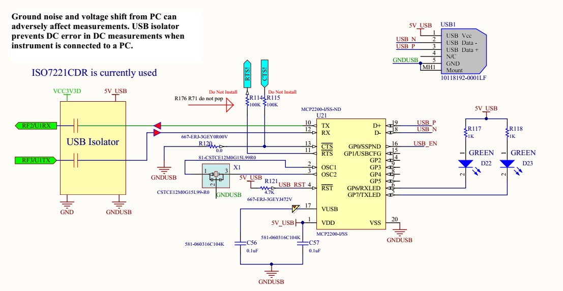
The USB port of the Multimeter + is electrically isolated from computer.![]()
![]() Isolated USB ensures that there will be no interference introduced by a PC power supply.
Isolated USB ensures that there will be no interference introduced by a PC power supply.![]()
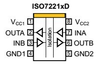
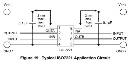
Typical application schematics:
![]()
The input and output signals are separated by an isolation barrier.
-
Initializing serial communication with Multimeter + LabView UI
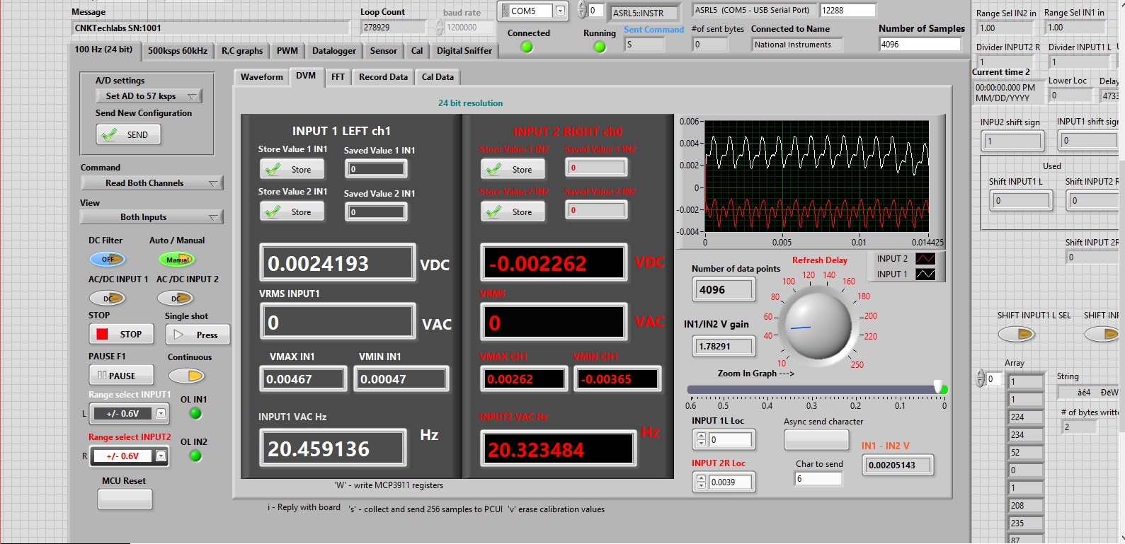
05/16/2016 at 17:40 • 0 commentsDVM (Digital Voltage Meter) page:
![]()
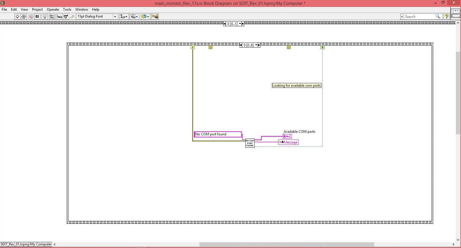
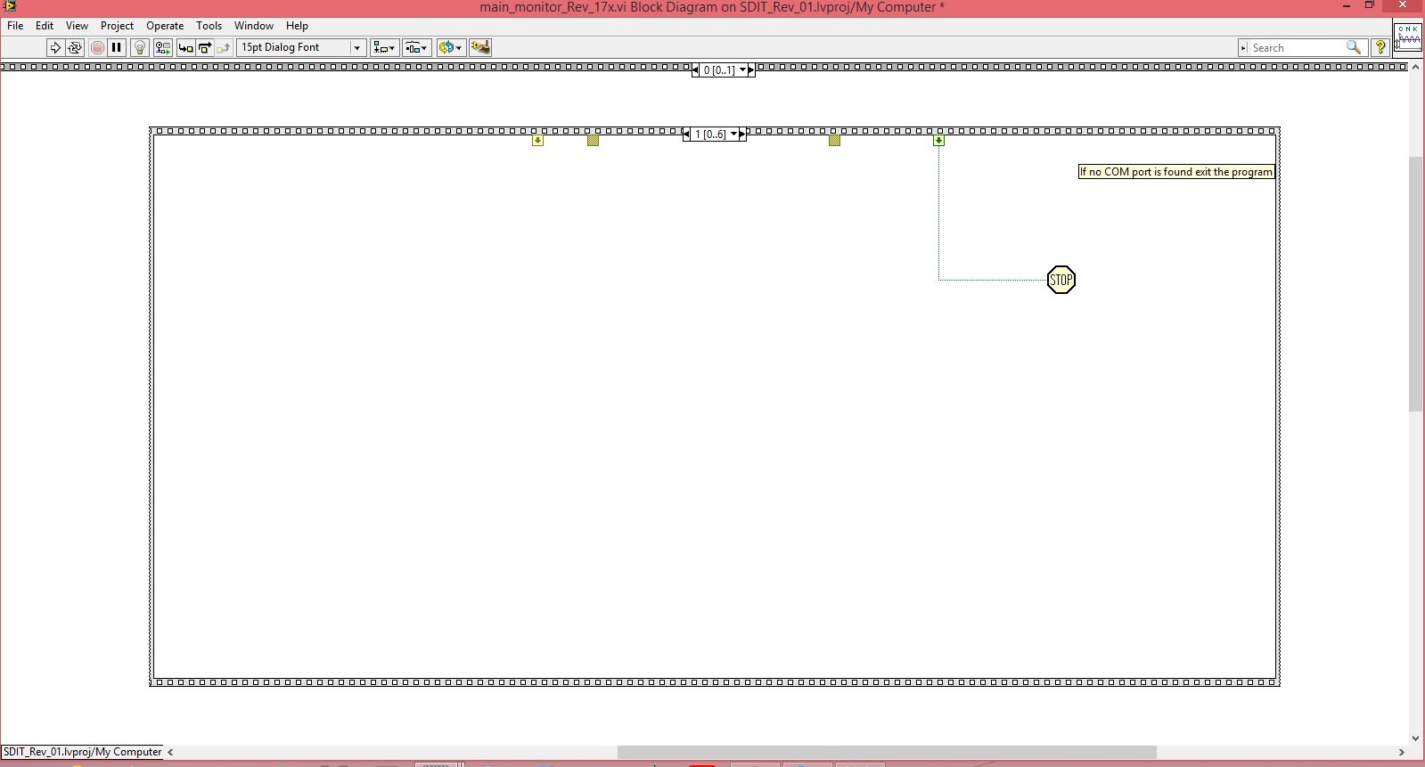
DVM (Digital Voltage Meter) shown above serial communication is initialized by running a series of LabView frames. The first frame shown in the image below searches for all enabled COM ports. If none is found it will return string “No COM port found” and the program will exit using “STOP” command.
![]()
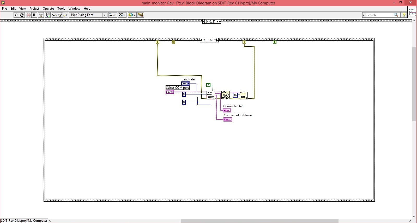
The following frame opens a serial communication with the![]()
selected COM port.
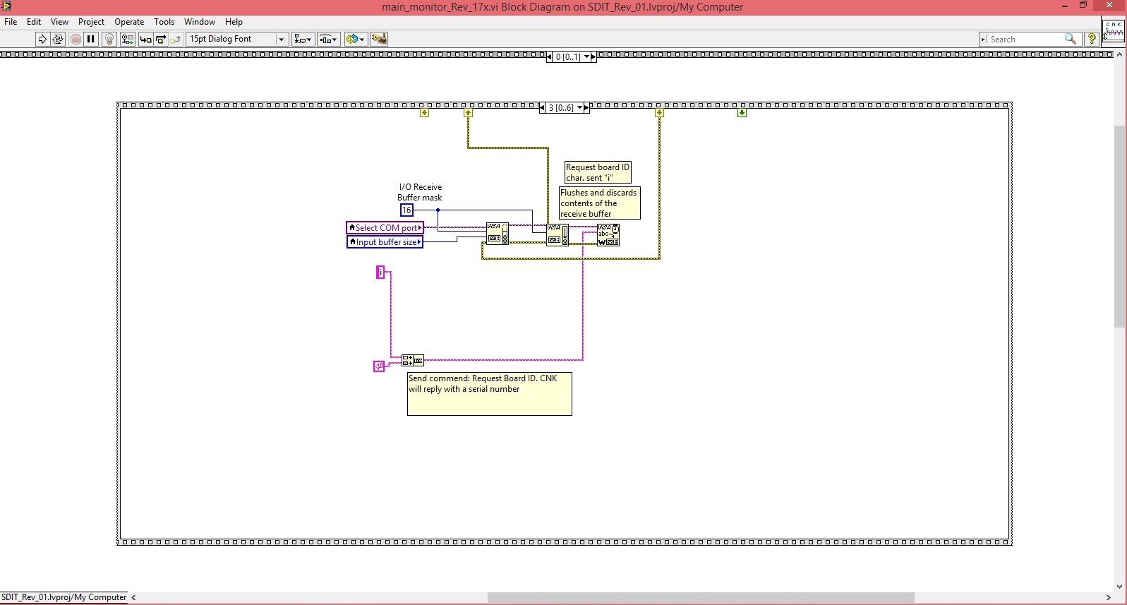
![]() Once the serial communication is established the program
requests board ID from the attached Multimeter +.
Once the serial communication is established the program
requests board ID from the attached Multimeter +.![]() Multimeter + responds with current Board ID:
Multimeter + responds with current Board ID:void send_board_id(void) { send_UART(board_ID); return; }![]() The board ID is received and program continues to the next step.
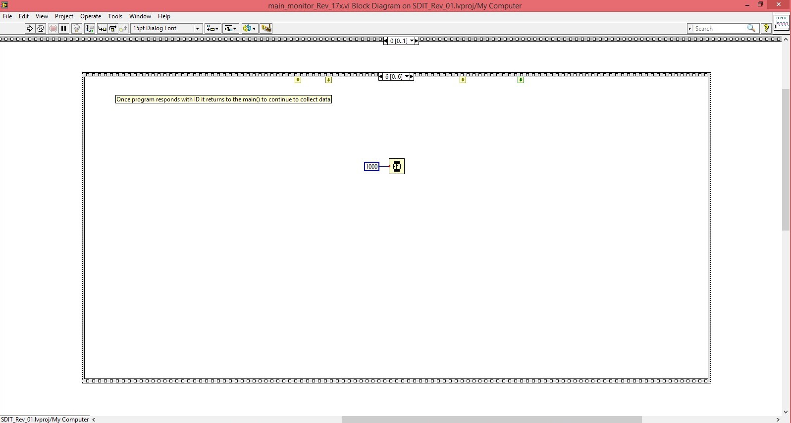
The board ID is received and program continues to the next step.I give it 1000 ms delay before the main loop starts running.
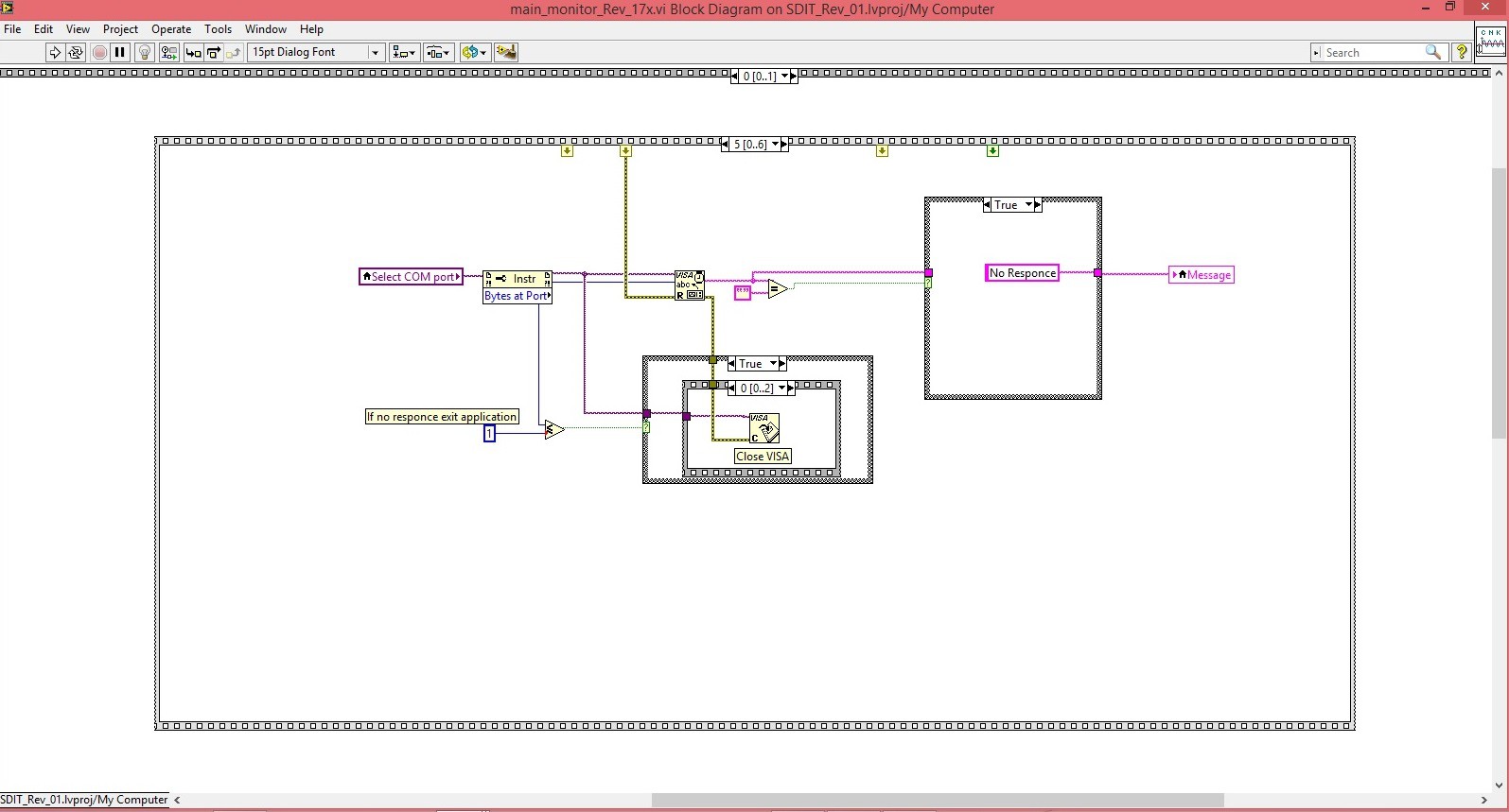
![]() The next step is to run the main loop where data gets collected and displayed continuously.
The next step is to run the main loop where data gets collected and displayed continuously. -
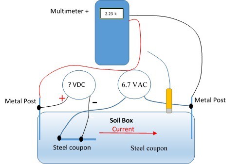
Measuring Soil Resistivity with Multimeter +
05/10/2016 at 22:35 • 0 comments![]()
I was working with my son on his science project “Impressed Current Cathodic Protection in Presence of AC Interference.” Impressed current cathodic protection is used to protect pipes (oil, gas, water lines) from rapid corrosion. Rectifiers are used more than any other source of impressed current power. Cathodic protection is a method of supplying electrons to a pipe such that when chemical corrosion processes occur at the surface of a pipe the pipe will not shed any electrons, but rather the cathodic system will supply electrons from an external power source, rectifier. It is often a difficult task to determine just the right amount of protection. One of the critical components of the experiment is the soil resistivity. Soil resistivity determines the amount of current flow from pipe into the soil. Higher soil resistivity results in lower currents flow. Basically pipe will corrode faster in wet soil than in dry soils or sands. I needed to measure soil resistivity and regular multimeter gives Open Line because it supplies DC current to the soil and soil gets charged like a capacitor. Multimeter + on the other hand measured soil resistivity very accurately. The reason is that instead of supplying DC current, Multimeter + sends a sort pulse during which it takes resistance measurement. After the reading is taken, pulse value drops to zero potential and soil has enough time to discharge. Then the process is repeated.
-
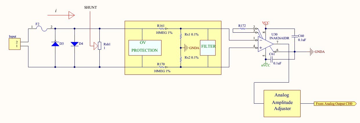
Measuring low currents in presence of noise.
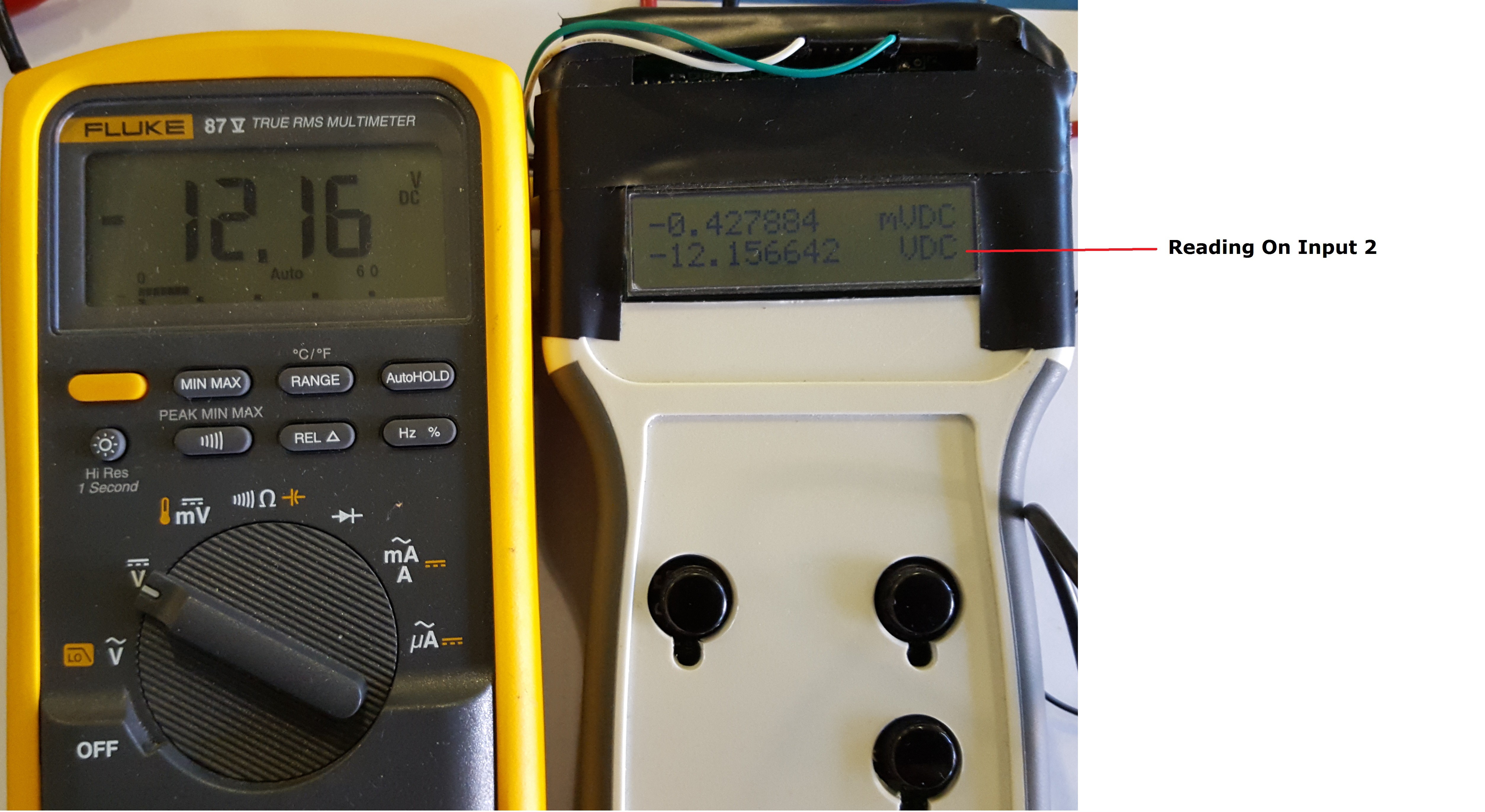
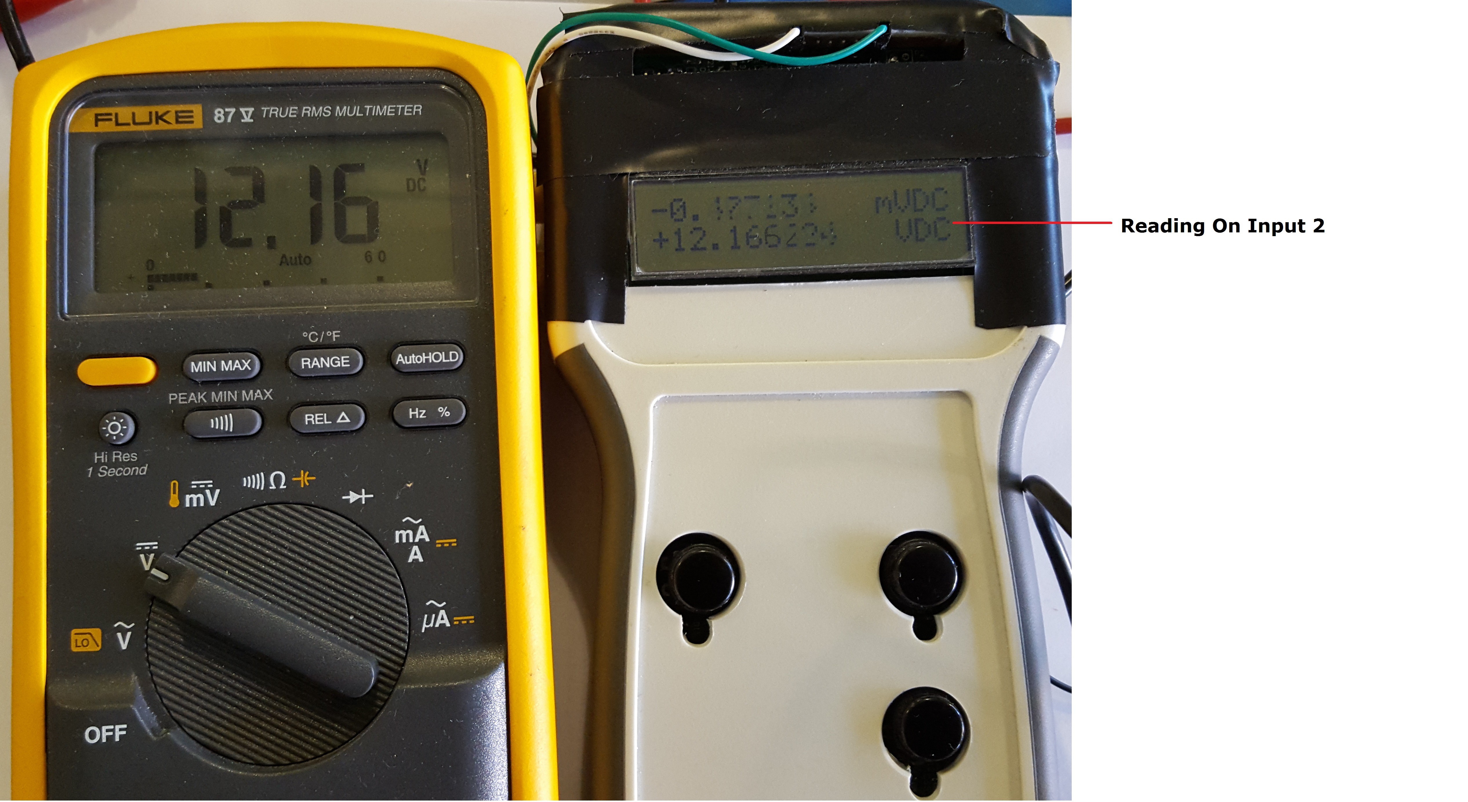
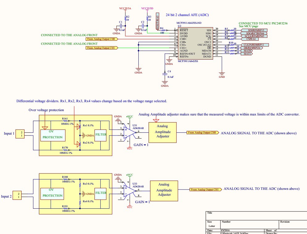
04/16/2016 at 03:08 • 20 commentsMeasuring low currents in presence of noise can be a challenge. In my device I use basic current sense configuration with a 1 Ohm shunt resistor and a differential amplifier feeding a 24 bit converter. The differential amplifier is set to gain = 1 to minimize noise and non-linear distortion.
![]()
RF coupled noise in magnitude of a fraction of a millivolt distorts readings and causes fluctuation in hundreds of micro amps. Since noise creates outlier values some basic statistical analysis can applied. Taking average of a large number of readings helps to estimate measured value, but the arithmetic mean is affected by all of the data, not just any selection of it. This is a good characteristic in most cases, but it is undesirable if some of the data are grossly in error, such as ?outliers? that are appreciably larger or smaller than they should be. Median values reduces fluctuation and helps to compute an accurate reading. If all the items with which we are concerned are sorted in order of increasing magnitude (size), from the smallest to the largest, then the median is the middle item. Consider the five items: 12, 13, 21, 27, 31. Then 21 is the median. If the number of items is even, the median is given by the arithmetic mean of the two middle items. Consider the six items: 12, 13, 21, 27, 31, 33. The median is (21 + 27) / 2 = 24.
Step 1 - take average of 2048 samples
Step 2 - record 10 averages
Step 3 - compute mean value of 10 averages.The following code snippet computes a mean value of 10 averages:
if (cntr < 10){
    vals[cntr] = voltage_val;// Collect data.
    cntr ++;                 // Global data counter
}
else{
    cntr = 0;
    for(i = 0; i < 10; i++) {// Calculating mean of 10 numbers
        for(j = i+1; j < 10; j++) { // j is the next element of i
                if(vals[j] < vals[i]) { // if(vals[i+1] < vals[i])
                    temp = vals[i];
                    vals[i] = vals[j];
                    vals[j] = temp;
                }
            }
        }

        voltage_val = ((vals[4] + vals[5]) / 2);
Computing mean of 10 average values reduced readings fluctuations from +/-0.5mA to +/-0.06mA, which is a major improvement.
-
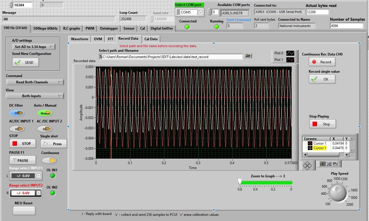
Data Record and Data Play
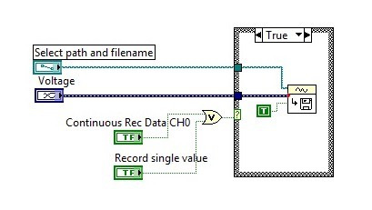
03/19/2016 at 14:45 • 0 commentsData Record and Data Play functions in LabVIEW.
![]()
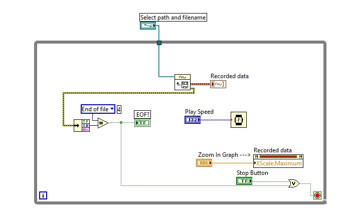
Data Record block diagram. Very simple :). Input data is "Voltage"
![]() Play Data block diagram. Also very simple diagram
Play Data block diagram. Also very simple diagram![]()
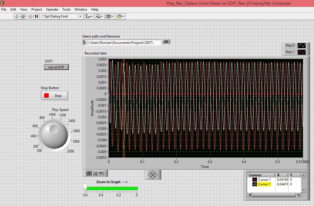
Play Data Front Panel. Play data file can be downloaded here.
![]()
-
Input Wiring and Coding
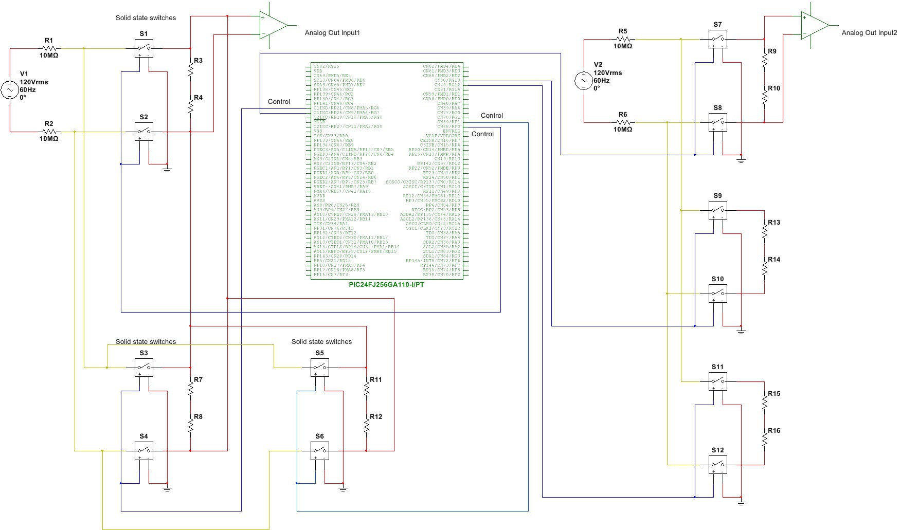
03/11/2016 at 00:03 • 0 commentsSimplified input diagram.
![]()
The embedded code size currently is close to 154 k-bytes (153981). It becomes a little tough to maintain and develop further. I have decided to develop a set of library functions to make it easier to develop code and test the unit. The following is an example of using TstAndResetVoltDiv() library function. This function takes care of verifying currently set input voltage dividers.
#include "MCP3911_EVB.h" #include "math.h" main { while(1){ switch( selection ) { case 1: case 2: //Set switch variable for the execute_function() rx_function = 13; //Starts measurement cycle and collects data samples. execute_function(); //Wait until all data is collected while (!buffer_full) {} /* * Function TstAndResetVoltDiv() is a library function. It is the first function called in the main() when * selection switch is set to 1 or 2. * This function runs continuously, it reads applied voltages witha previously selected voltage * dividers. * If the measured voltage is within the range, the previously selected divider values will be used * and displayCH0CH1() function will re-display the updated, more accurate, voltage readings. */ TstAndResetVoltDiv(cflag,rng_srch,c_smple_sum,current_sum_n,curre nt_sum_p,cal, CH1vsftSgn,CH1vshft,dividerCH1,vflag,v_smple_sum,volt age_sum_n,voltage_sum_p, CH0vsftSgn,CH0vshft,dividerCH0,buffer_full); Break; } } -
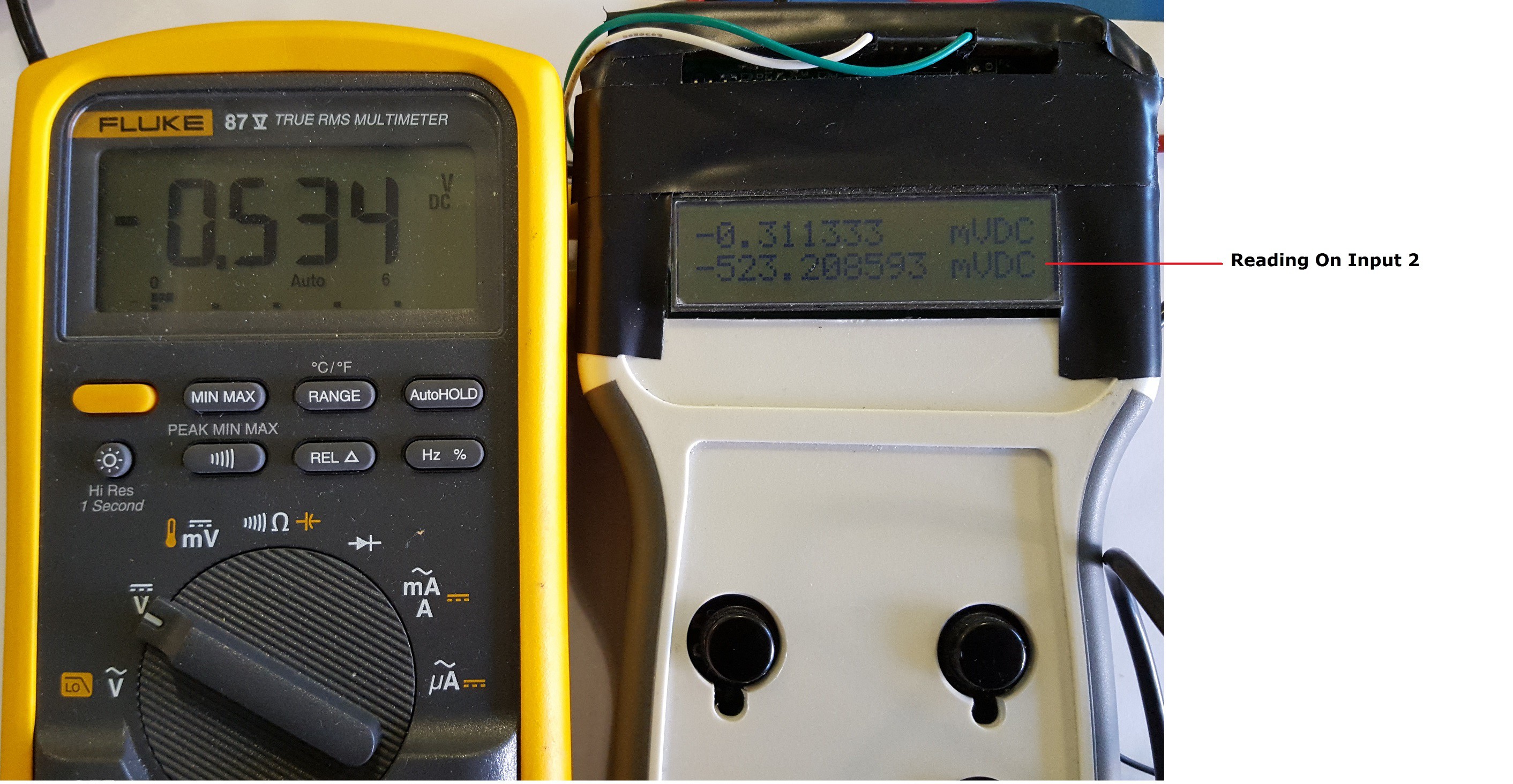
Working on accuracy
03/08/2016 at 20:08 • 0 comments![]()
![]()
![]()
Have 2% error in mV range (bad). Volt range seems to be ok.
-
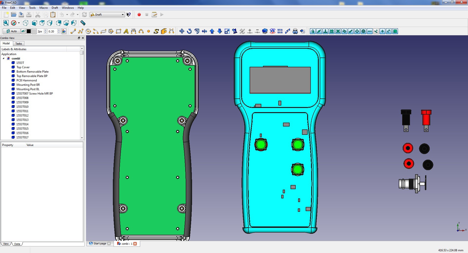
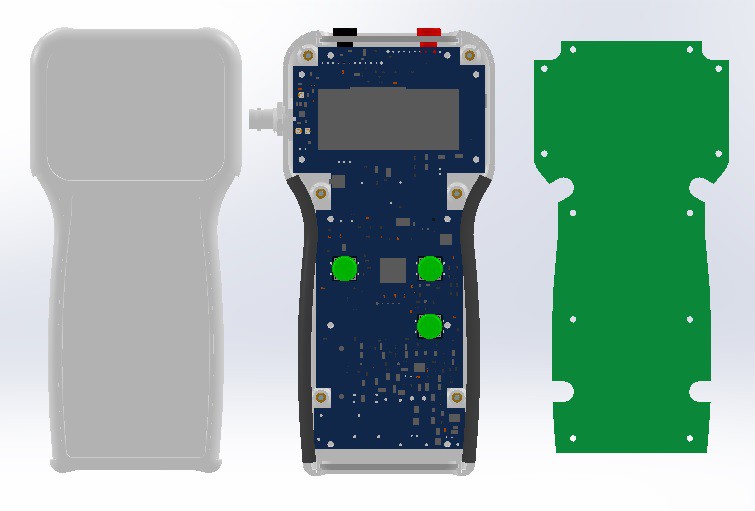
Struggling with 3D modeling
02/29/2016 at 19:58 • 0 comments![]()
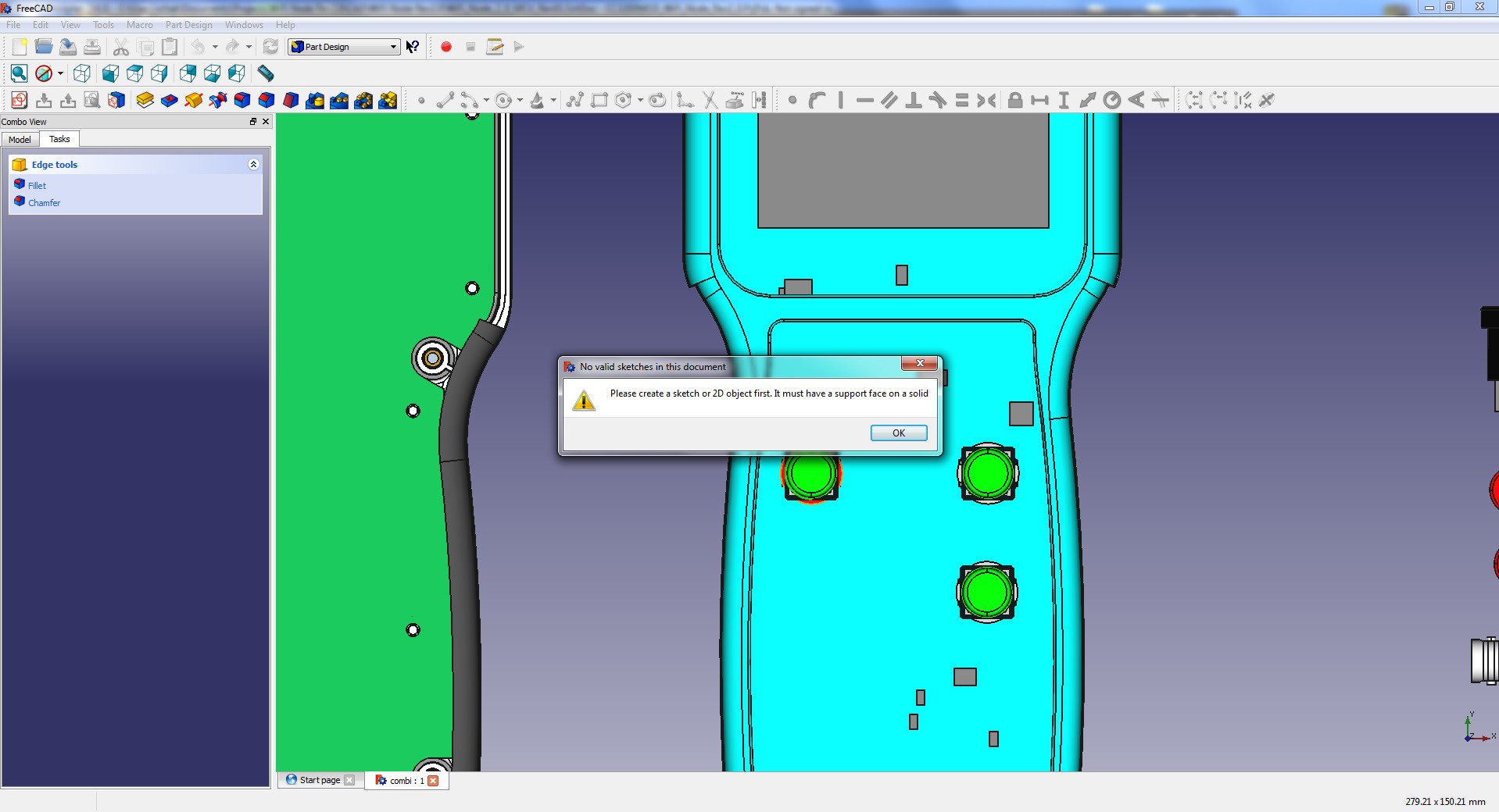
I have imported step files for my 1553 case as well as the PCB and aligned them together. Now I need to make all the cutouts for pushbuttons and the LCD. I have created a circle sketch, shown in red color, and tried to make a pocket with
![]()
And I get
![]()
![]()
-
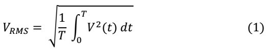
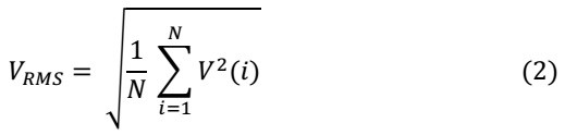
RMS
02/27/2016 at 03:33 • 0 commentsRoot mean square (RMS) is a fundamental measurement of the magnitude of an AC signal. Defined practically, the RMS value assigned to an AC signal is the amount of DC required to produce an equivalent amount of heat in the same load. Defined mathematically, the RMS value of a continuous signal V(t) is defined as:
![]()
For time sampling signals, RMS calculation involves squaring the signal, taking the average, and obtaining the
square root![]()
I use equation 2 to compute RMS value of the incoming AC signal. When AC input is detected the instrument
collects 2048 samples of data if both channels are running or 4096 samples for a single channel. The data gets
processed according to equation 2 and RMS value is computed. The following is INT2 interrupt routine to compute sum of squares. The interrupt is triggered on data ready pulse from MCP3911.void __attribute__((interrupt, no_auto_psv)) _INT2Interrupt(void) { union { unsigned long nvoltage; // Negative values struct { unsigned char voltLSB : 8; unsigned char voltNSB : 8; unsigned char voltMSB : 8; unsigned char voltd : 8; }; } negative; unsigned long voltage_sum_p_sqr; // Compute sum of squares voltage_sum_p_sqr =voltage_sum_p_sqr+(negative.voltMSB * negative.voltMSB); }Most of AC measurement from my experience are high in amplitude, usually in Volts. So, using only MSB
byte of the 24 bit value gives me good resolution for all of the AC measurements. Once sum of squares is calculated Vrms is computed using equation 2.v_smple_sum = (voltage_sum_p_sqr / buffer_lenght); RMS = sqrtl((long double) v_smple_sum);
Multimeter +
Dual input 24 bit Multimeter with USB interface, single channel 10 bit USB oscilloscope, PWM out, 2 Ch Data-logger, R, C, Digital sniffer.

 Play Data block diagram. Also very simple diagram