JohSchneider
-
flicker free software-PWM for the backlight
03/15/2016 at 19:17 • 0 commentsjust using wiring-pi or the python GPIO classes to drive a software pin did work, but tended to flicker ever so often - since there is so much software overhead involved and the kernel rescheduling the python process :P
what seems to work much better is a software-pwm that uses the hardware PWM/PCM subsystem of the broadcom chip - like
https://github.com/sarfata/pi-blaster/
with some minor modifications to the source and the '-pcm' switch set (can't use the PWM subsystem, since it will be busy generating audio) the LED (used as placeholder for the backlight circuit) stopped flickering :-D
NB: there is another trade-off: by using the PCM subsystem for software-pwm we lose the serial-console. so if one needs the (hardware)serial to debug, the backlight service has to be disabled
-
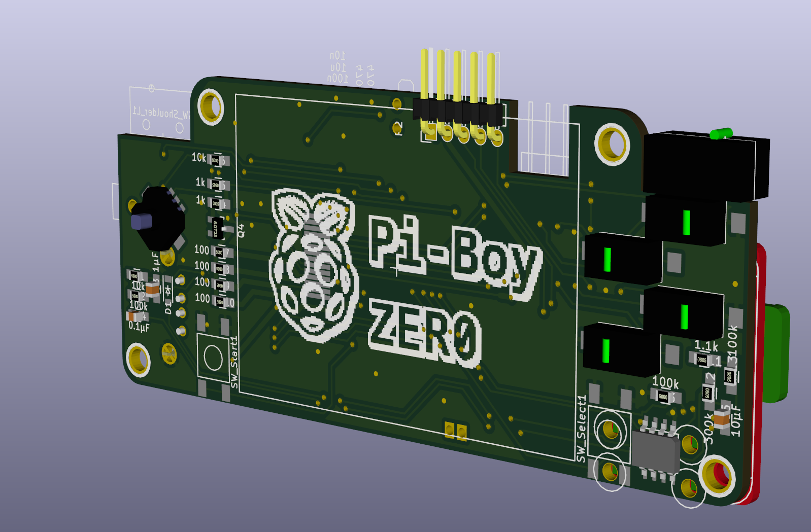
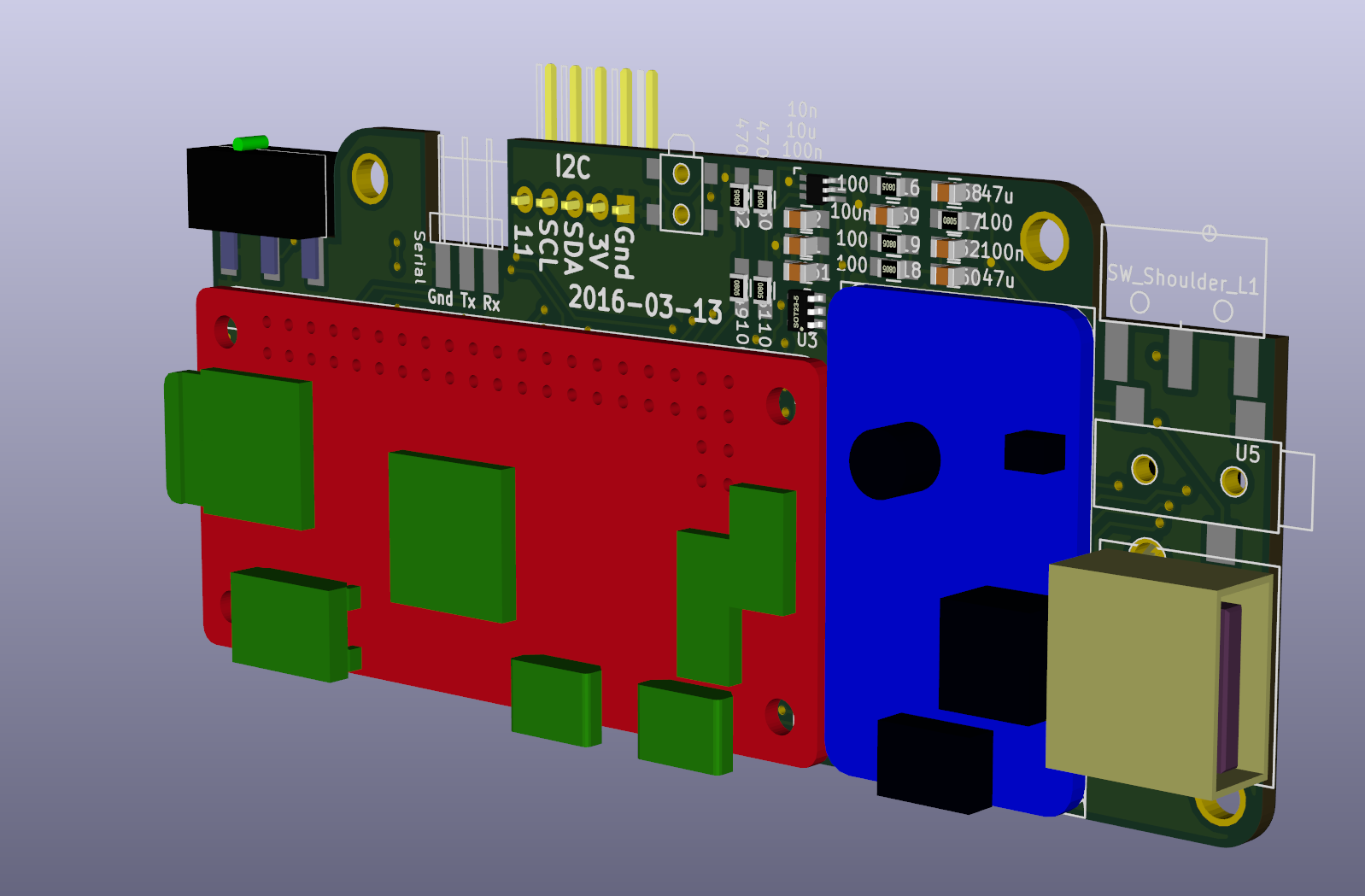
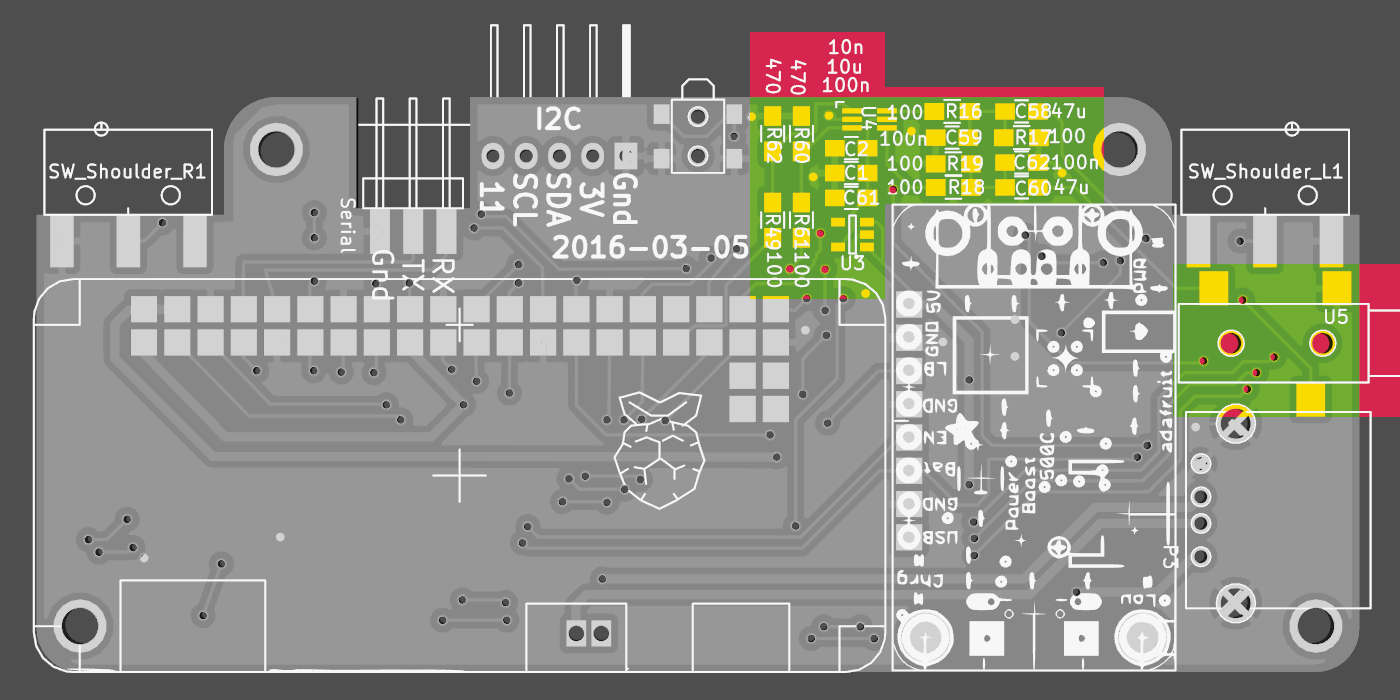
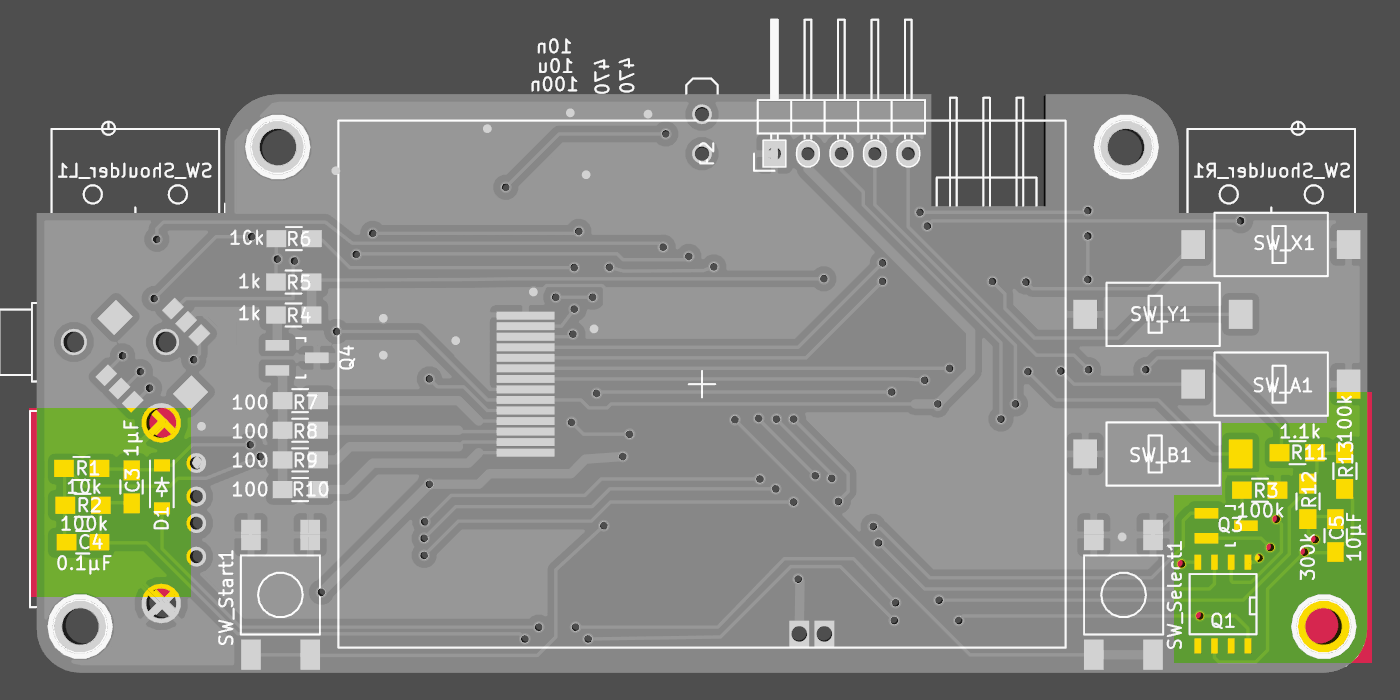
new board revision - with logo :-)
03/13/2016 at 09:12 • 0 commentsand 3d-components!
![]()
![]()
this revision fixes these errors:
- missing trace connecting powerboost:bat-low to the pi-zero
- wrong transistor pinout Q3 - turned out to be not needed and removed anyway- clearance for protuding hdmi-connector tabs
- mounting holes undersized
- rerouted usb-traces (equal length, less vias and traces crossing)- corrected usb-solder pad position
- wrong pinout on BJT transistor for backlight
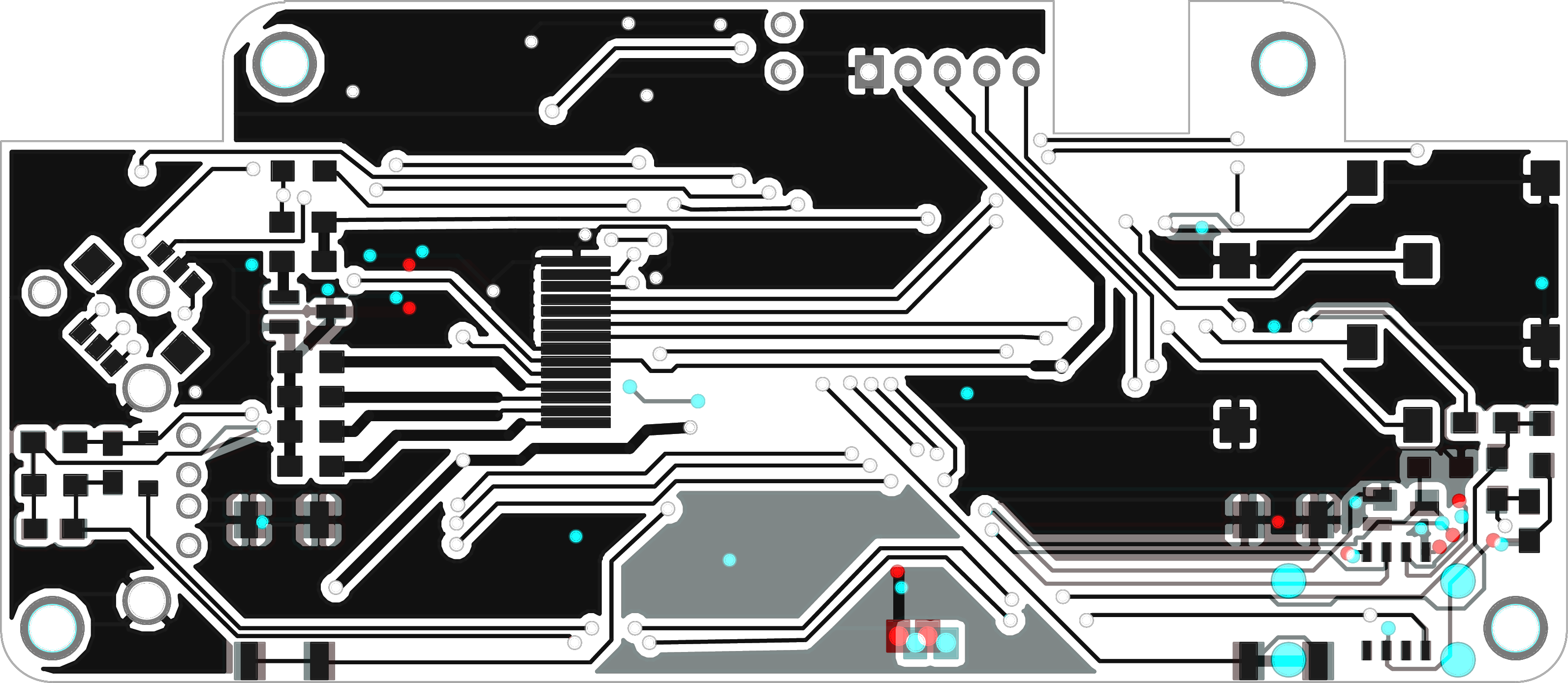
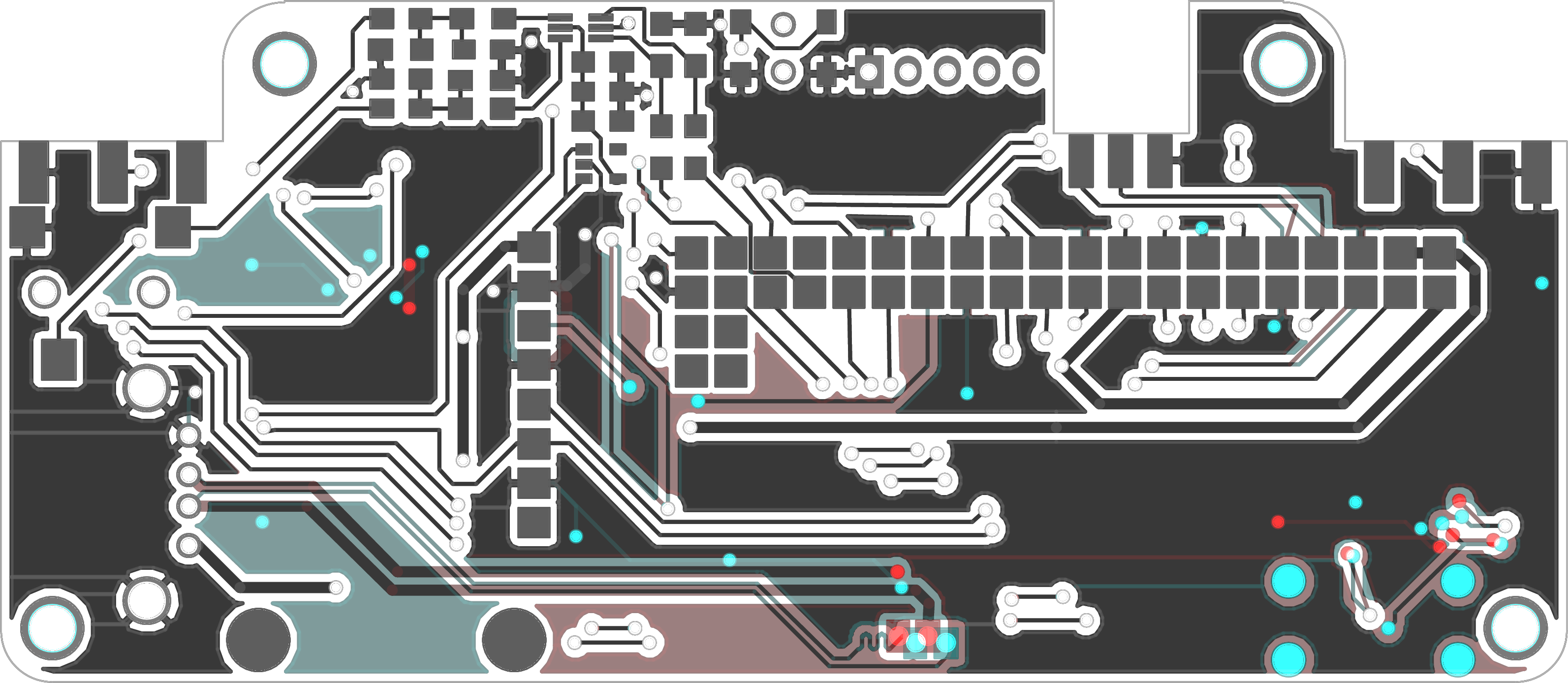
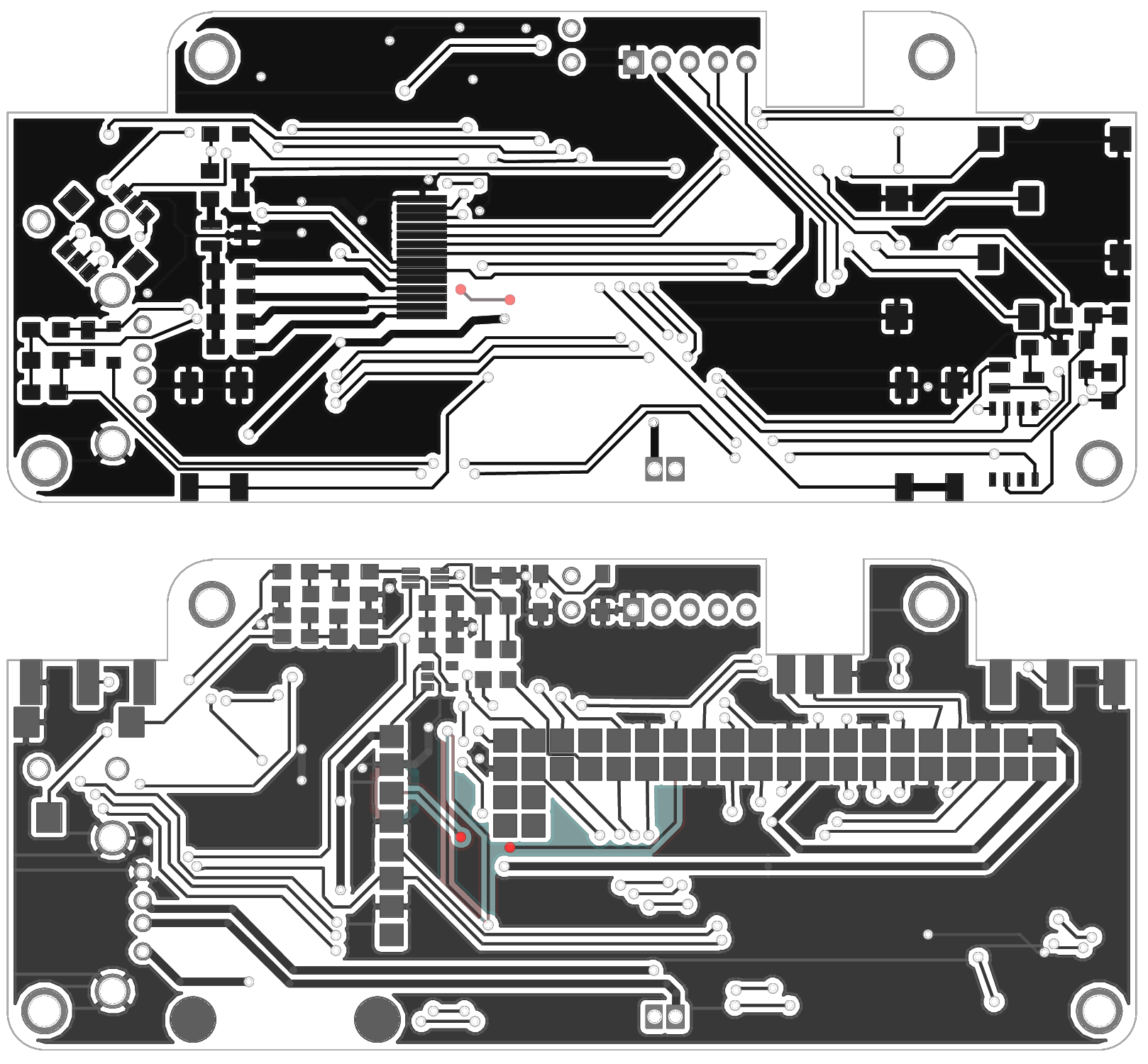
diff of the copper layers:
![]()
![]()
-
solder&test 2: audio
03/08/2016 at 17:21 • 0 comments![]()
putting the components for the audio filter in, only for one channel though - since there will be a follow-up revision to address the other bugs found so far. still this tells us if audio this way works or not
![]()
and it does! :-D
somewhat audible sound came out of this mini speaker (just salvaged it out of a broken tablet to see if it works, don't intend to keep it hooked up) - the target in-ear headphones worked even better :-)
the software side followed this adafruit tutorial:
https://learn.adafruit.com/adding-basic-audio-ouput-to-raspberry-pi-zero/pi-zero-pwm-audio
the next steps on the audio topic would be to read-up on the device-tree configuration to properly setup the two pwm channels instead of the on-the-fly configuration
-
more problems...
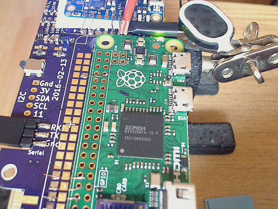
03/07/2016 at 14:23 • 2 commentswhile the front solder pads line up nicely
![]()
![]()
the through-hole solder-points for the usb connection do not :-(
![]()
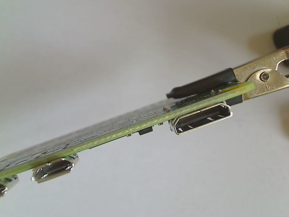
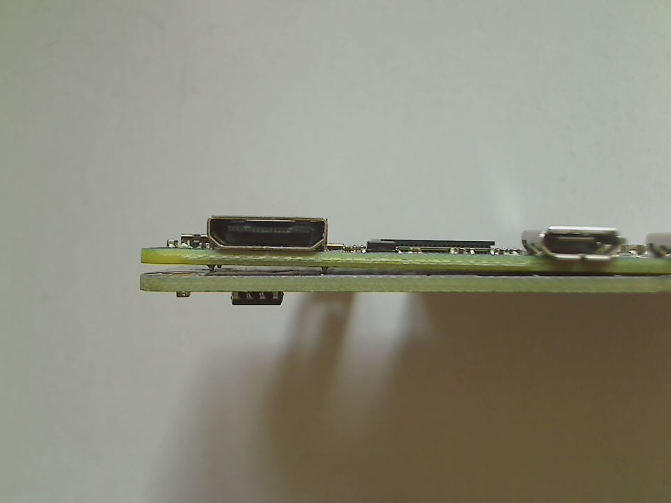
another problem - which wasn't visible in the pictures of the pi zero - is that the back side is not completely empty and flat, the hdmi socket has some mounting tabs which protrude a tiny bit
![]()
![]()
will have to include some sort of cutout to accommodate those :-\
this is what happens if you start designing a PCB without the major components at hand to recheck the dimensions :-P
oh well, i'll keep on adding and testing the other functional groups - maybe there are more bugs waiting to be uncovered :-)
-
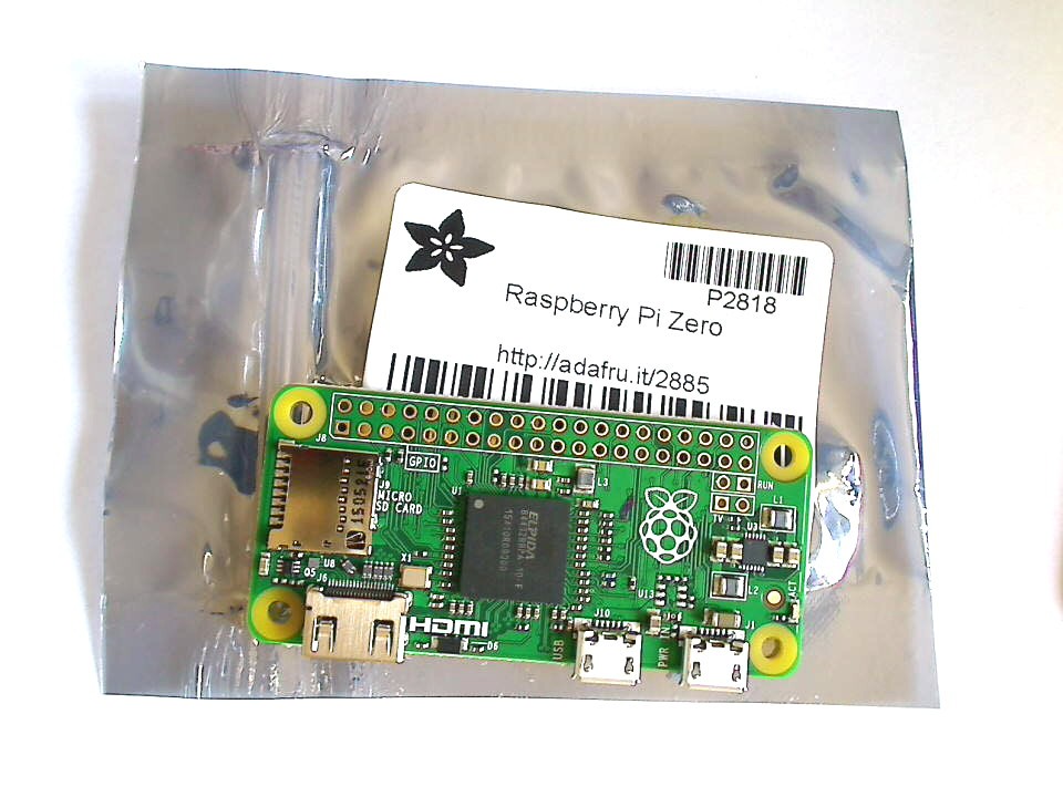
So bright... so beautiful... ah, Precious.
03/07/2016 at 14:01 • 0 comments![]()
just came with the mail :-D - point of origin: Pasadena CA
thanks Adafruit and Hackaday!!
-
solder&test 1: soft-power
03/05/2016 at 10:46 • 0 commentsputting the components on the pcb, grouped by function - power is first
![]()
![]()
and temporarily mount the power-boost pcb (to ease removal in the worst case) - looks ugly, but gets the job done...
![]()
the two wires connect to the LiPo Battery - in the final assembly the battery will be directly soldered to those pins, since the battery jst-socket is (intentionally - was a trade-off decision...) blocked by the USB-A socket
And the next bug... ordered the wrong transistor that pulls on the enable pin of the PowerBoost... have to fix the BOM and order another one :-\
update 2016-03-10replacement transistor arrived, turned out it didn't work as intended either :P
after some playing around with it, noticed that the pulldown (to the powerboosts enable pin) without the inversion/buffer transistor in-between just works...
since the voltage levels in the soft-power part (tow latching mosfets) are already on V_Batt level, and the connection to the raspberry is "protected" by another resistor, everything should be fine. the whole soft-power circuit was designed to turn 5V on/off, so the 3-4.2V of the lipo shouldn't hurt the pi (should, should, ...).
updated the schematics and boardlayout accordingly (see github)
-
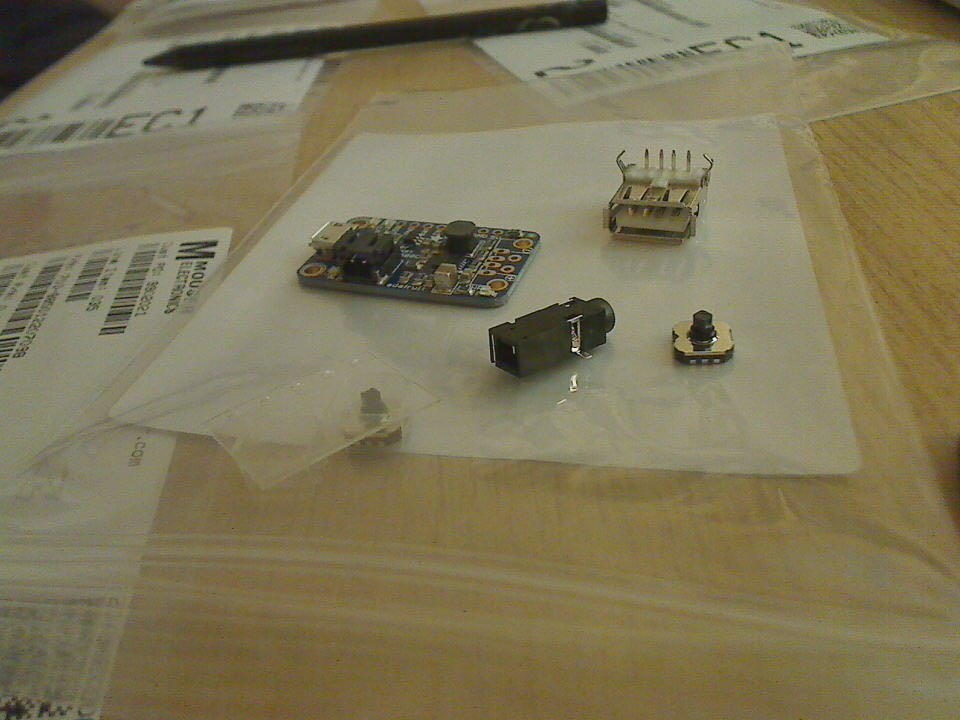
parts arrived
03/03/2016 at 21:39 • 0 comments![]()
word to the wise: don't put smd parts for multiple projects into one order, or see to it that the part-reference is reflected in the packaging listing of the distributer - spent the better part of the evening picking them apart due to a slight mistake in the BOM (which has been fixed and pushed to git) :-P
-
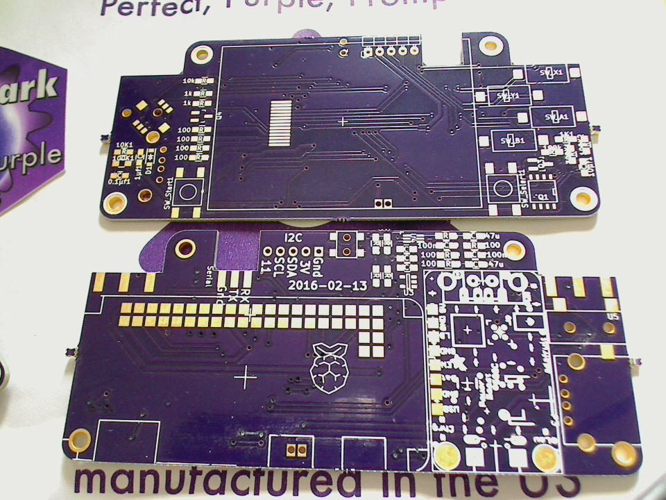
PCBs arrived :-)
03/02/2016 at 13:23 • 1 comment![]()
beautiful purple :-)
still waiting on the shipment with all the other components though - got delayed because of some parts where not in stock :-\
time to sanity-check the pcbs...
-
licenses...
02/26/2016 at 01:15 • 0 commentsjust noticed that i didn't add a license text to the github repository, which one to pick...
- the CERN Open Hardware License looks interesting ( http://www.ohwr.org/projects/cernohl/wiki )
- so does the (L)GPL...
but the former only seems to cover hardware design files, whereas the later only covers software/libraries (the scripts and code that will be added later) :-/
... let's fall back to an MIT license for the time being :-)
-
spottet first minor mistake
02/18/2016 at 18:53 • 0 commentsstill waiting for the first pcbs to be made and arrive, and already found the first bug - forgot to wire the low-battery pin to the raspberry :-P
already fixed it in the schematic, but will have to jump-wire that one on the pcbs...
![]()
PiBoy-Zero
yet another portable console! ;-) roughly the size of a gameboy micro, with a 2.2" display