JohSchneider
-
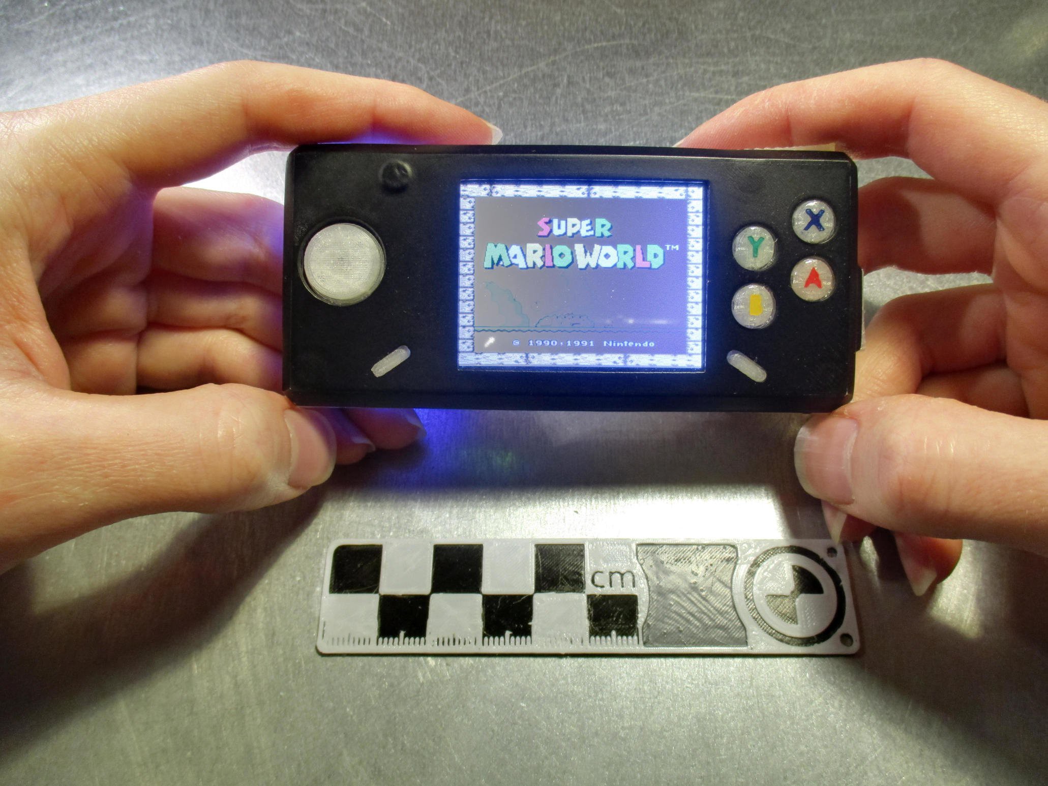
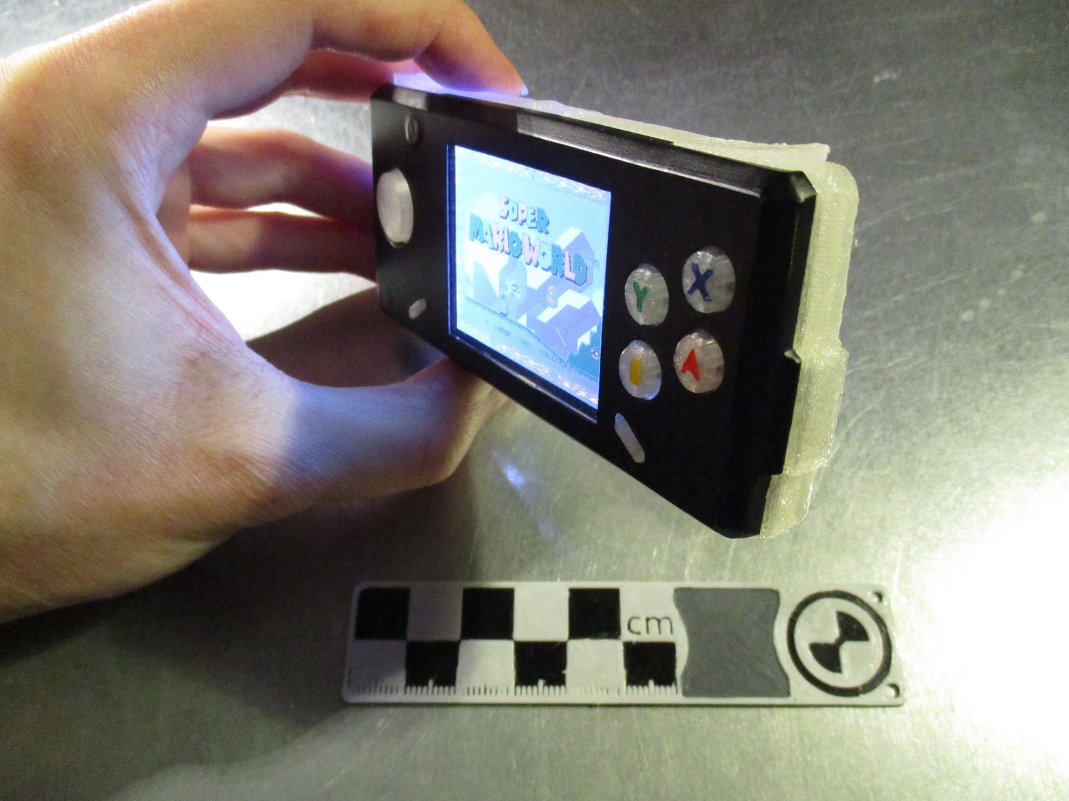
current state & ABXY buttons
11/02/2016 at 18:14 • 0 comments![]()
been using the Pi-Boy on and off for the last couple of months - works beautifully :-)
some things need to be redone though;
- messed up front panel (heat-setting M3-thread *after* painting was a dumb idea...)
- the power button needs a redesign (button-cap is missing)
- have to add a bit material to the back/front to close the slight gap between the two
![]()
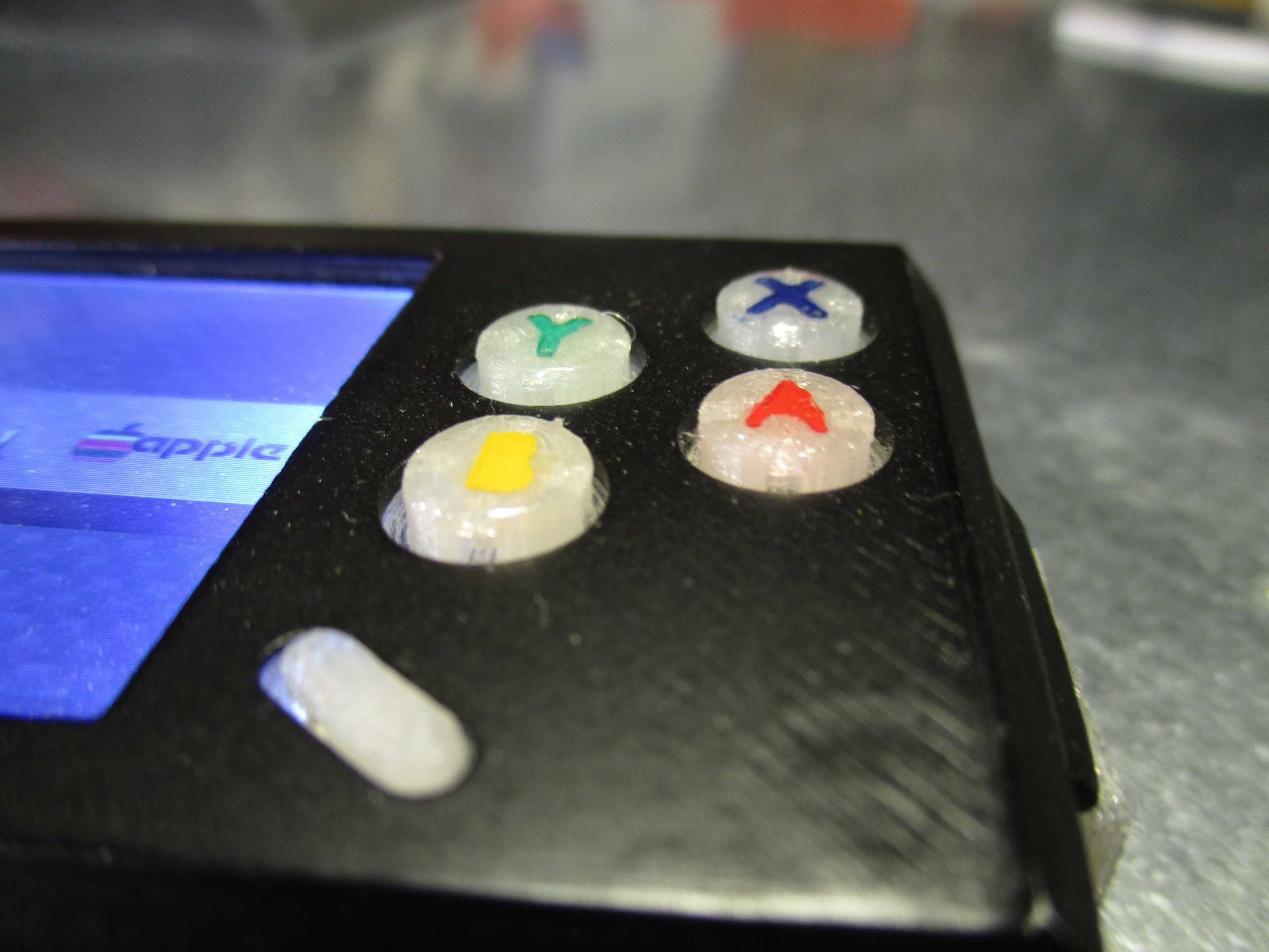
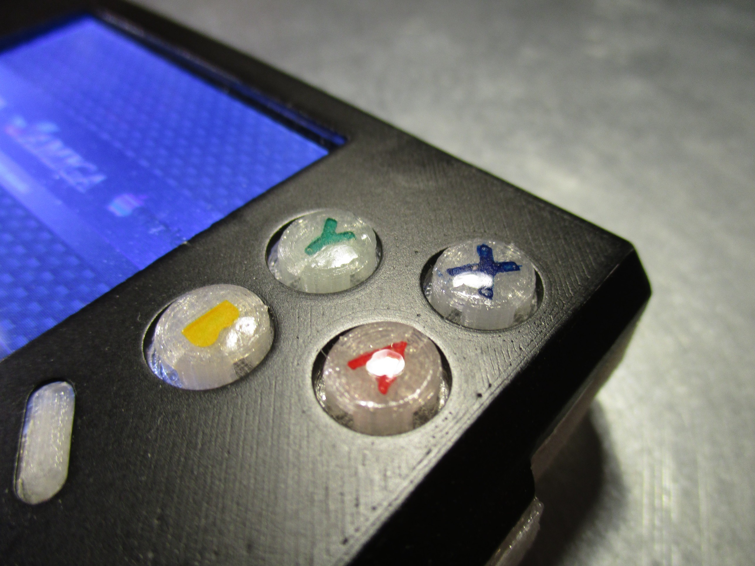
on a side note: what turned out really well where the ABXY buttons - the combination of the soft-tactile omron switches plus a coat of epoxy feels just right while playing :-D
![]()
![]() the way i build them was:
the way i build them was:- print the button-piece (one part, all four are connected by a bridge - to ease assembly) with the letters indented
- fill the letters with acrylic paint
- put a drop of XTC-3D (some other epoxy might work too) on top to form a slight dome
-
milestone: it lives!
04/09/2016 at 15:27 • 6 commentsfor the thirtieth log something special - it lives! :-D
- battery: check
- display: check
- controls: check
- sound: check
all systems go:
![]()
there are still many rough spots:
- on the software side there are many daemons still missing (pwm back-light, power management, ...)
- the system needs further configuration: the buttons currently only work in emulation-station menu, not the emulators (probably sth minor)
- the case needs further refinement, lots of sanding, priming and a few layers of paint :-)
- the setup/configuration steps need more documentation or better: scripted as far as possible (rough script already on github)
- print and assembly instructions?
-
case prototyping
04/09/2016 at 14:28 • 1 commentcreating a 3d printable case from the rough sketches done earlier
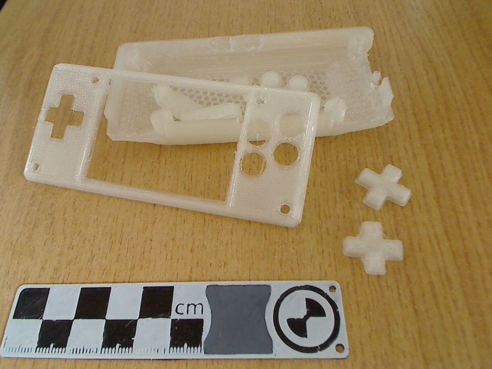
the overall shape was put toghether relatively quickly - but getting the d-pad to feel right took some iterations, the first few where still cross-shaped
![]()
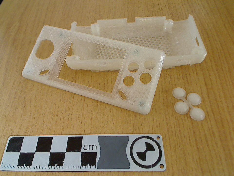
turned out, that shrinking and making it round works better for the alps switch. connecting the ABXY buttons eases installation
![]()
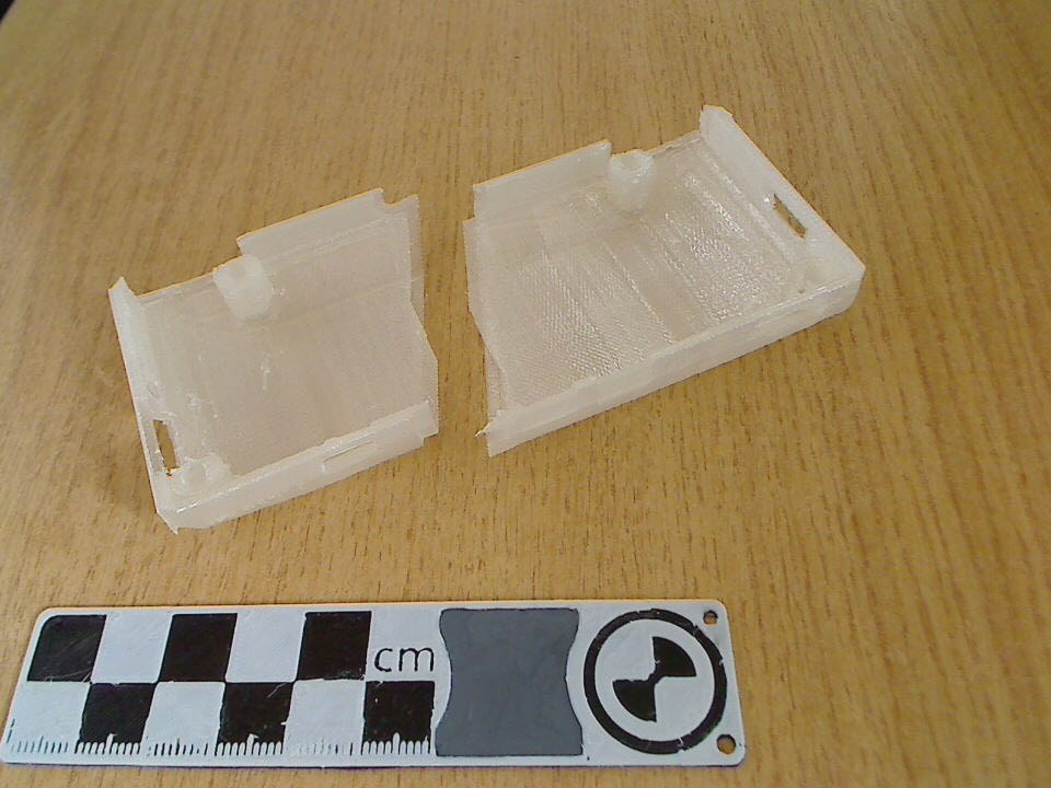
also playing with the back part, for example splitting it in two with overlapping part along the seam:
![]() which would be printed standing up:
which would be printed standing up:![]() this would have the upside of a sturdier frame - but on the downside prints waaay longer, with increased risk of print failure and the split/seam doesn't look as nice as a single-pice backside does, paintability would probably be another issue - so i'll stick with the single-piece for now
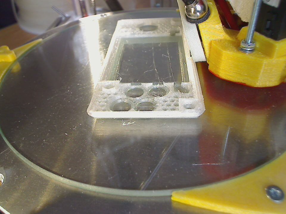
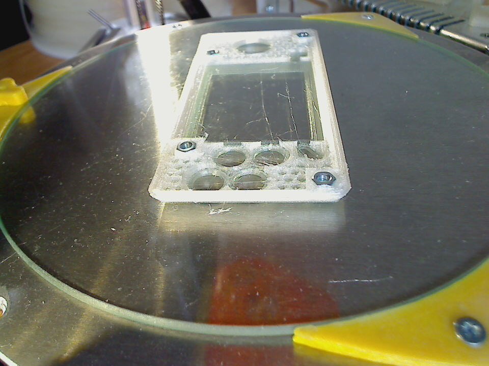
this would have the upside of a sturdier frame - but on the downside prints waaay longer, with increased risk of print failure and the split/seam doesn't look as nice as a single-pice backside does, paintability would probably be another issue - so i'll stick with the single-piece for nowbtw: the front piece in its current form uses the pause-print-insert-M3-trapped-nuts-resume-print approach:
![]()
![]()
STLs to print your own are on github :-)
-
and another minor mistake...
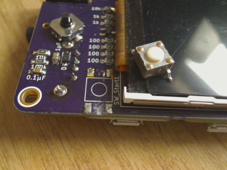
04/02/2016 at 14:25 • 2 commentsanother wrong footprint...the push buttons used for start/select group their four pins in pairs - the other way round
... really need to learn to double check the datasheet for all components that have more than two leads - even trivial ones like buttons :-P
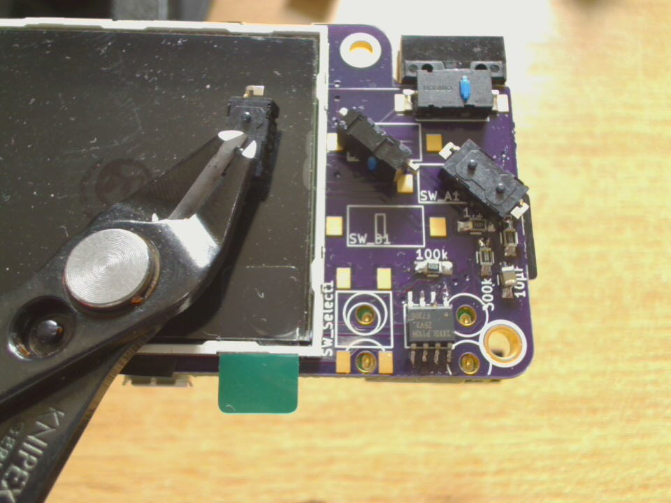
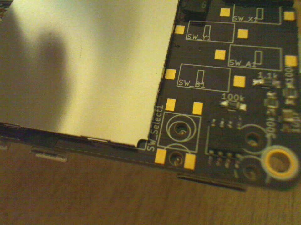
oh well - the fix was to desolder the button, cut some traces and amputate a leg >:-)
![]()
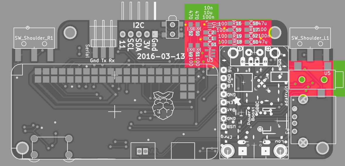
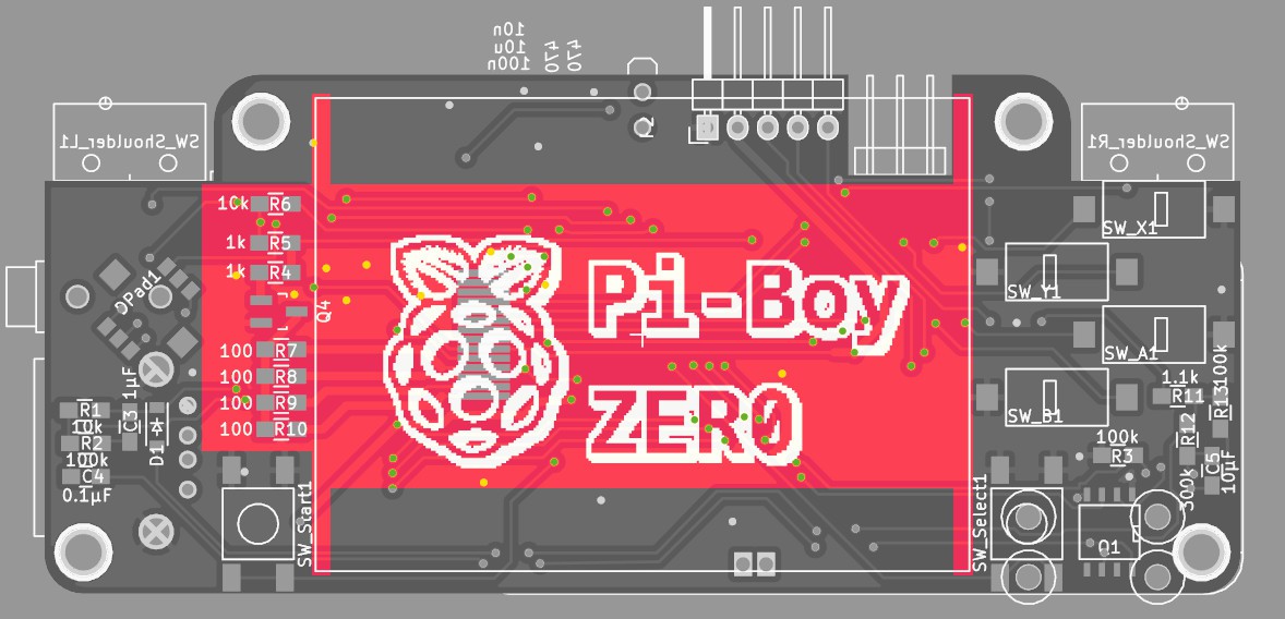
updated the pcb layout and pushed the changes to git and osh-park
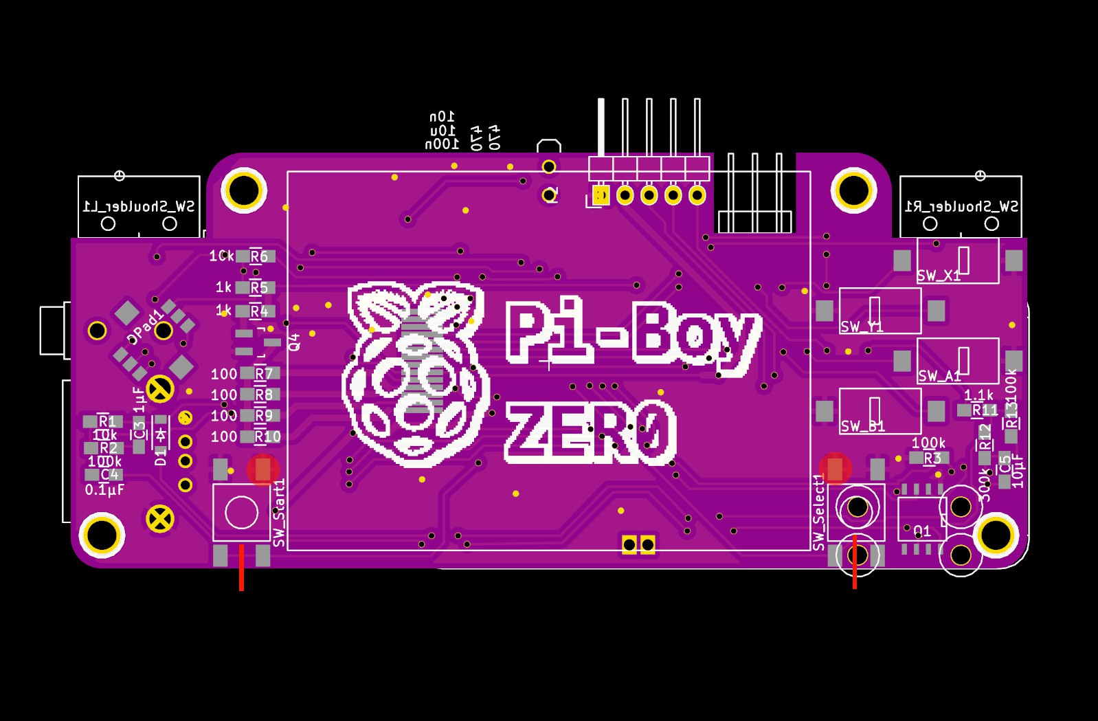
update 2016-04-13for anyone who happen to have this buggy version, the fix looks like this:
![]()
cut the start/select traces at the red lines, and do not solder the button pads marked with the circle...
-
soldering the remaining components
04/02/2016 at 14:14 • 0 commentsmainly buttons and the usb socket...
the usb-socket has mounting tabs which i decided to trim down at the side close to the alps-nav switch, just in case the room is needed later on by the 3d printed that'll come ontop of it
![]()
the omron switches chosen for ABXY have some position keys on the back, which have to be trimmed also -- which was a design decision, including holes for those would have interfered with the smd-pads on the other side
![]()
in retrospect it would have been a bit easier to mount the tft last, since it sits close to some solder-pads... but it was still doable
-
Pi Zero PWM Audio - device tree overlay
04/02/2016 at 11:03 • 3 commentsthe adafruit guide for pwm-audio on the pi-zero ( https://learn.adafruit.com/adding-basic-audio-ouput-to-raspberry-pi-zero/pi-zero-pwm-audio ) configures the gpio-alt functions on the fly to remap the audio-pwm pins from hidden ones to pins on the gpio-pinheader
after reading up ondevice tree configurations and tracking down all necessary pieces, i got this this code snippet/overlay to do the same at boot-time:
/dts-v1/;
/plugin/;

/ {
  compatible = "brcm,bcm2708";

  fragment@0 {
    target = <&gpio>;
    __overlay__ {
      pinctrl-names = "default";
      pinctrl-0 = <&pwm_audio_pins>;

    pwm_audio_pins: pwm_audio_pins {
	brcm,pins = <13 18>;   /* gpio no ('BCM' number) */
	brcm,function = <4 2>; /* 0:in, 1:out, 2: alt5, 3: alt4, 4: alt0, 5: alt1, 6: alt2, 7: alt3 */
	brcm,pull = <0 0>;     /* 2:up 1:down 0:none */
      };
    };
  };
 };
this maps the left channel to pin 33 (BCM=13) and the right channel to pin 12 (BCM=18)
compiled with:
dtc -@ -I dts -O dtb -o pwm-audio-pi-zero-overlay.dtb pwm-audio-pi-zero-overlay.dtsand enabled by appending this line to the /boot/config.txt:dtoverlay=pwm-audio-pi-zero
helpful links:
http://elinux.org/RPi_BCM2835_GPIOs - pins and alt functions for the pi-zeros cpu
https://learn.adafruit.com/introducing-the-raspberry-pi-zero/audio-outputs - the other adafruit guide, touching opi-zero pwm audio
https://www.raspberrypi.org/documentation/configuration/device-tree.md - general documentation on devicetrees on raspberryhttps://www.raspberrypi.org/documentation/configuration/pin-configuration.md
https://www.kernel.org/doc/Documentation/devicetree/bindings/pinctrl/brcm,bcm2835-gpio.txt - documentation on the gpio pinconfig via dtoverlay
https://github.com/fivdi/onoff/wiki/Enabling-Pullup-and-Pulldown-Resistors-on-The-Raspberry-Pi - good example of gpio config via dt-overlay
-
solder&test MK2
04/01/2016 at 20:15 • 0 commentsok, again repopulating the board with the components grouped by function (the raspberry-zero and the powerboost 500 are already mounted)
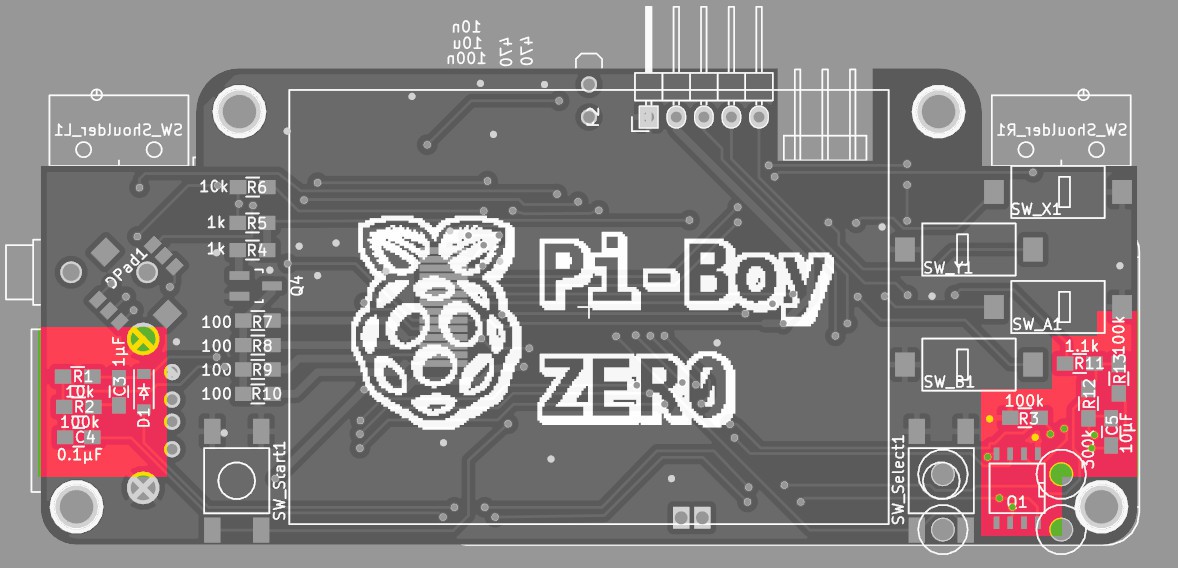
first: soft-power
![]()
![]()
connecting the lipo battery and hitting the power button the pi boots, and pulling the gpio down powers it of :-D
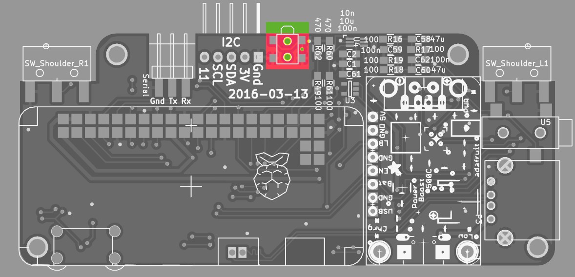
second: audio
![]()
NOTE: the components in the top right corner are left/right channel = two times the same set, but their placement got a bit mixed up = is not symmetrical... oh well, just have to follow the silkscreen :-P
Testing the audio with a pair of headphones: works! :-)
(when nothing is playing - eg the channels are silent - there seems to be a tiny bit of high frequency noise coming from somewhere - and sd-io is also slightly audible... i wonder if that is just due to the anaolog/pwm nature of the system or bad board design/soldering :-S )
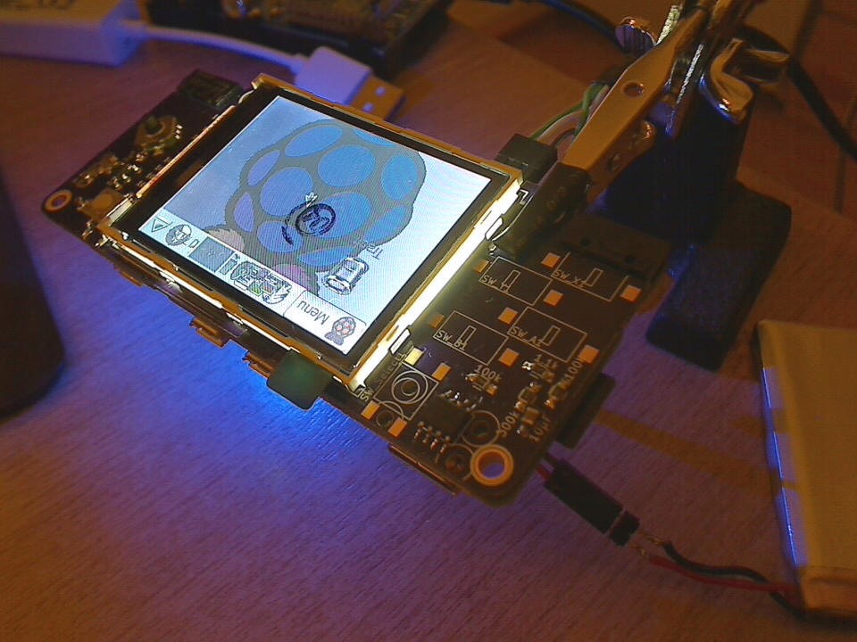
third: backlight and tft display:
![]()
the 2.2" display is held by a metal bracket, which in turn is glued with strips of double sided tape to the donor-pcb.
a sharp knife makes short work of these:
![]()
reapplied double-sided tape to the bracket and glued it to the pi-boy pcb - aligned to the right edge of the silkscreen square
Note: are some contacts on the front-side of the pi-boy-pcb that need to be masked of with insulating tape befor glueing down the metal braket!![]()
transplanting the tft screen:
* the ribbon cable of the screen was desoldered from the donor-pcb with the previously mentioned tea-candle method
* pre-tinning the contacts on the pi-boy pcb
* and finally re-soldering the 14 contact
* double/tripple check the solder-joints/solder bridges since the contact pitch is ultra small :-P
powering the hole thing up and we have picture! :-D
![]() (upside down, but thats easily fixed in the config)
(upside down, but thats easily fixed in the config) -
hand soldering the raspberry to the baseboard
04/01/2016 at 13:54 • 2 commentssimilar projects that mounted the raspberry onto another pcb seem to reflow it in some way or another, with a hot-air rework station or similar tools. the same is doable with a good fine tipped soldering iron.
these steps seemed to produce good results:
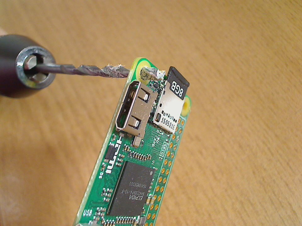
1) widen the mounting hole near the hdmi to 3mm, which will be used as position key (and later on by a screw holding the case together) - done by hand, very carefully :-)
![]()
2) pre-tin all the surface mount pads on the base-board with a slight (!) amount of solder
![]()
3) use a M3 screw to get an accurate position, clamp the boards together and solder by first heating up the rim of the pin-hole, then feeding solder into it until the hole is roughly half filled. at this point it should connect with the pad below and visibly suck the solder a bit down
![]()
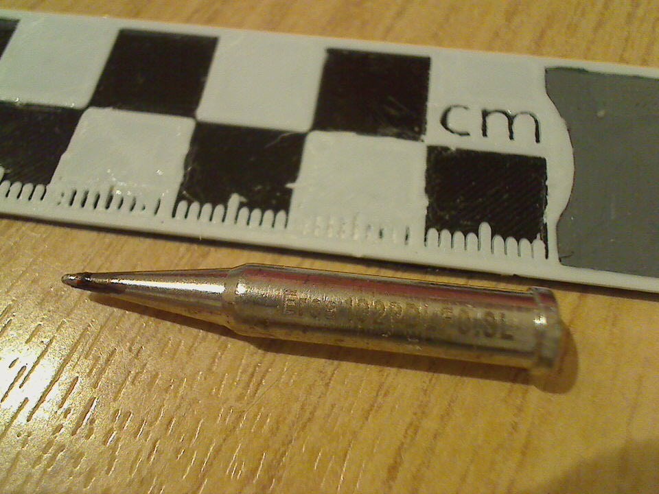
the tip i used fit halfway through the pin-holes, which i could put into the soldered holes that seemed to have a hard time connecting to the pad below (was the case with some of the holes connected to the ground plane, since they sucked the heat away pretty fast)
![]()
-
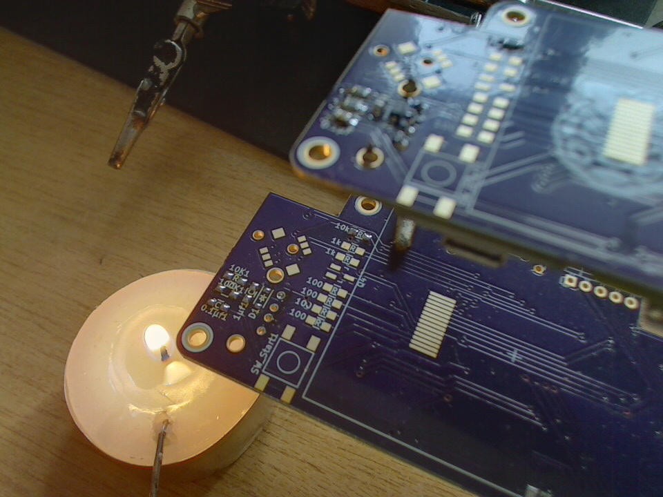
candle-light desoldering
03/31/2016 at 19:13 • 0 commentsnot wanting to discard the perfectly good smd-components that are already on the Mk1 pcb a candle-light desoldering session was in order: the Mk1 pcb below - roughly 1cm above the flame of a small tea light candle - and the Mk2 above ready to receive the transplant
![]()
moving the candle under the specific components to desolder; small tweezers in one, the solder iron in the other hand - worked like a charm :-)
-
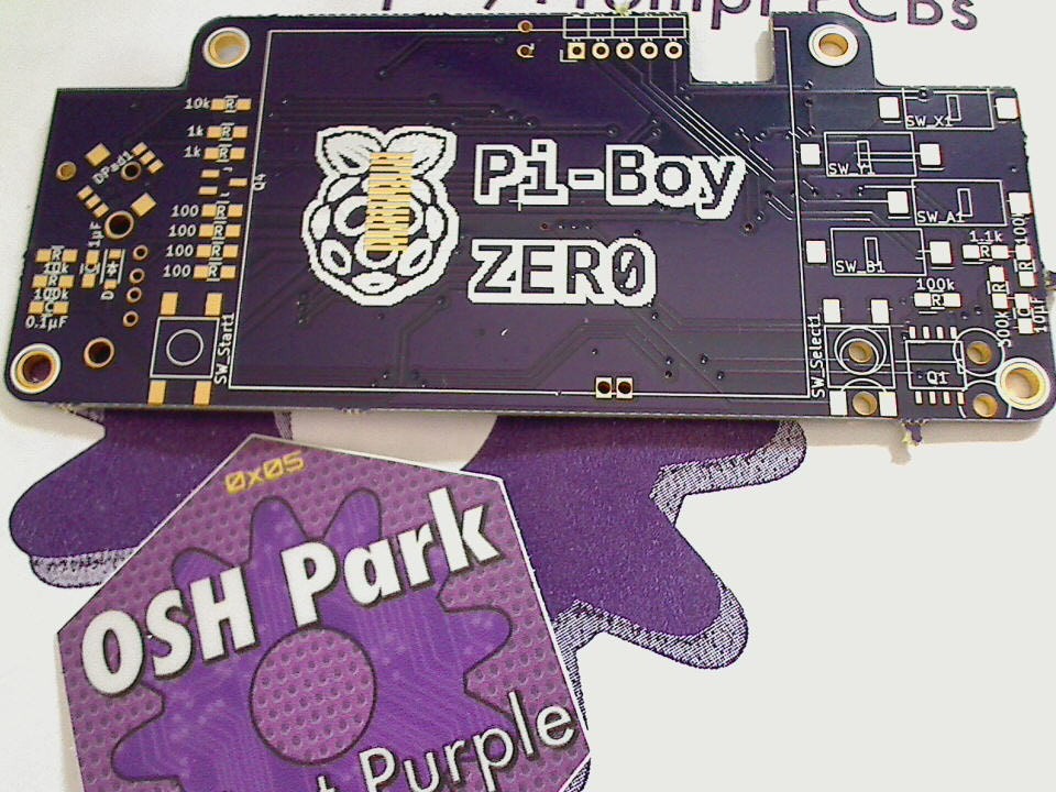
PCBs Mk2 arrived :-)
03/31/2016 at 13:57 • 0 comments![]()
things of beauty :-D
time to desolder the Mk1 and populate the Mk2...
PiBoy-Zero
yet another portable console! ;-) roughly the size of a gameboy micro, with a 2.2" display
 the way i build them was:
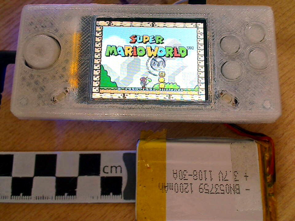
 which would be printed standing up:
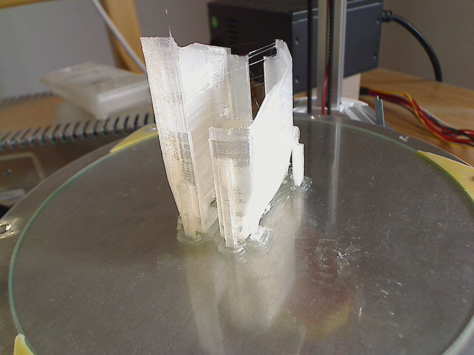


 (upside down, but thats easily fixed in the config)