-
1Using The Compute Module 3
The Raspberry Pi Compute Module 3 is a very powerful core board for prototyping some interest gadgets. Detailed introduction can be found here. And some useful information can be found here.
The module uses a DDR2 SODIMM type connector, which is a slightly harder to use. In addition all the GPIO pins of the BCM2837 core BANK1 and BANK0 are lead out.
To start using the compute module, we need to provide several different voltages: 1.8V, 3.3V, 2.5V and 5.0V. Among them, 1.8V and 3.3V are used to power some peripherals which need about 350mA each. The 2.5V power line drives the TV-out DAC and it can be tied to 3.3V as we do not need TV-out feature. The 5.0V should be connected to the VBAT pins and it powers the Core. The VBAT input accepts voltages range from 2.5V to 5.0V and just make sure the power supply can outputs up to 3.5W. VCCIO pins (GPIO_XX-XX_VREF) can be connected to 3.3V as we use a 3.3V CMOS level. The SDX_VREF pin should also be connected to 3.3V.
All the HDMI, DSI, CAM pins are not used here, just leave them float. Remember to tie the EMMC_DISABLE_N pin to 3.3V as we will use a TF card as the hard drive instead of the USB boot feature.
The Pi need to know what is function of each GPIO. Here I provide some files, put "dt-blob.bin", "bcm2710-rpi-cm3.dtb" and "config.txt" in the boot folder of a newly flashed TF card. The put the "dcdpi.dtbo" in the /boot/overlay folder. The dt-blob.bin defines the default function of each GPIO. I change the GPIO14/15 to normal GPIO and move the UART0 function to GPIO32/33 as we need GPIO14/15 to interface with the LCD module. I also tell the Pi to use GPIO40/41 as pwm function and make them to be the right and left audio output. The dcdpi.dtbo is a device-tree overlay file and it tells the Pi that we will use GPIO0-25 as DPI function. Finally, we write "dtoverly=dcdpi" to aware the Pi to load the overlay file we provided.
-
2Interfacing the LCD Module
As different DPI/RGB interface LCD module may be used in this console, here we take the module used in my own build as example. And if you chose a different one, check the pin definition of your module and just make the connections according to the pin names as showed in the example.
There are two interfaces on the LCD module: an SPI and a DPI. The SPI is used to configure the initial settings of the LCD driver IC and we can connect them to any unused GPIO. Only connect the Reset, CS, MOSI(SDA/SDI) and SCLK(SCL) pins, the MISO(SDO) pin is not used. To initialize the LCD driver, here we use the BCM2835 C Library to drive the GPIOs and outputs a certain initialize sequence provided by the module supplier. The source file can be found at the end.
Install the BCM2835 C Library on another Raspberry Pi 3 according to the instructions here. Then use the command "gcc -o lcd_init lcd_init.c -lbcm2835" to compile the source file. Then add a new line in the /etc/rc.local file before "exit 0": "/home/pi/lcd_init"(assume you have put the compiled application under /home/pi folder). It should be emphasis that the source file is only used for the certain module I used and for a different LCD module, just ask the supplier for a initialize sequence and modify the source file accordingly. This process is quite tricky because at this point nothing can be seen from the screen, that's why I strongly suggest you do this on a RPI-CMIO board as it leads out all the GPIOs so you can debug it with uart or wlan.
The following part is easy, just connect the left pins of the LCD module according to here. Depends on what kind of LCD module you have got, chose the RGB mode wisely. For me, here I chose the DPI_OUTPUT_FORMAT_18BIT_666_CFG2(mode 6). Alter the "dpi_output_format=0x078206" line according to your choice. And if your LCD module uses a different resolution, adjust the "hdmi_timings=480 0 41 60 20 800 0 5 10 10 0 0 0 60 0 32000000" refering to the file here.
If all the settings are correct, on the next boot up of your Pi, you should see the display on the screen after a 30-40s black(from power to system loads your SPI initialization script).
-
3The Key Pad and Audio
A game console needs keys and buttons. Here we need 10 ALPS SKPDACD010 switches as the up/down/right/left, LR and A/B/X/Y buttons. And normal 6x6 surface mount keys are used for other buttons like start/select and volume-up/down.
There are two ways to interface the buttons with the Raspberry Pi. One way is connecting the buttons directly to the GPIOs on the Pi and another way is connecting the buttons to an MCU and interface with the Pi through USB HID protocol. Here I chose the second one, because we need an MCU to deal with the power on sequence anyway and it is safer to keep the Pi away from human touch.
So, connect the keys to the STM32F103C8T6 and then connect the MCU to the Pi with USB. An example of the MCU program can be found at the end. Alter the pin definitions in hw_config.c and compile it with the MCU's USB library found here. Or you can just download the hex file directly to the MCU as long as you share the same pin definitions in the schematic at the end.
As for the audio outputs, the official schematic of the Raspberry Pi 3 B gives a good way of filtering the pwm wave and the same circuit should work perfectly here. One thing that should be point out is that remember to add the "audio_pwm_mode=2" line at the end of config.txt in order to lower the noise of the audio output.
In order to drive the speaker, a speaker driver is needed. Here I chose the TDA2822 and the circuit is the official BTL circuit. Note that the phone jack PJ-327 has a auto detach pin on the right output. When there is no headphone plugged in, the pin 3 is connected to the right channel. And as soon as the headphone is plugged in, this pin is detached from the right channel. This pin can be used as the speaker input pin and the speaker will mute when headphone is plugged in.
-
4The Power
There are 3 power sections: the MCU supply, the Charger/Booster and the DC-DC Bucks.
The MCU supply is divided from all other power supplies because we need it to perform the pre-powerup sequence. As the power button is pushed down, the PMOS will connect the EN pin of the LDO to the battery to enable the LDO. The MCU is then powered up (the button is still pressed). At the boot up of the MCU, it will check if the power button is pressed long enough. After about 2 second, if the MCU found the power button is still pressed, it will pull up the "PWR_CTL" pin to keep the PMOS on. At this moment, the MCU takes over the control of the MCU power supply.
When the power button is pressed for 2 second again, the MCU will run the power down sequence. At the end of power down sequence, the MCU will release "PWR_CTL" pin to let the PMOS shut off and the MCU supply is then disabled.
The charger/booster part uses the IC IP5306. This IC is 2.4A charge and 2.1A discharge highly integrated Soc for power bank usage and it is perfectly fit for our needs. The IC is able to charge the battery, to provide a 5V output and to show the battery level with 4 LEDs at the same time.
The DC-DC Buck part uses two SY8113 high efficiency 3A buck. The output voltage can be programmed by 2 resistors. To ensure the power sequence, we need the MCU to enable the Booster first. The KEY_IP signal will simulate a key press to the KEY pin of IP5306 and enables the internal 5V booster. After that, the MCU will enable the 3.3V buck by pull RASP_EN pin high. And after 3.3V is provided, the 1.8V buck's EN pin is pulled high and enables the 1.8V output.
As for the battery, two 1000mAh Li-ion batter is enough for the console. The normal size of this kind of battery is around 50*34*5mm.
-
5Setting Up the System
First, you need to download and flash the RetroPie image into a new TF card. Tutorial and download can be found here. Download the Raspberrypi 2/3 version. You will see 2 partitions after flash the image: a "boot" partition of FAT16 format and a "Retropie" partition of EXT4 format.
When you have done, do not insert it to the Raspberry Pi instantly because we need to add a FAT32 partition for the roms. Use partition tools like DiskGenius to adjust the EXT4 partition to about 5-6GB and make a new FAT32 partition with all the free space left on your TF card. Refer to the Picture I have uploaded.
Make sure your system is able to identify the TF card reader as a USB-HDD device and you will see 3 partitions in your explorer. Two of them are accessible and Windows will ask you to format the left one. DO NOT format it!!
First open the "boot" partition and follow Section 2 to setup the pin configurations. Or you can just unzip the boot.zip at the end, and copy all the files and folders to your boot partition. Remember to copy the compiled lcd_init script into the boot partition too.
Here we are ready to perform the first boot, but as there is no display I strongly recommend you use a RPI-CMIO board with a usb wlan device. Then you may configure the wpa_supplicant file and enable ssh here. However, if you do not intend to get one, GPIO32/33 can be used as a UART terminal. Connect the TX(GPIO32) and RX(GPIO33) pin to a usb-to-uart board and access the terminal with the baud rate of 115200. Either way, you need to get a terminal access to your Pi.
At the first boot, the system will stuck when try to expand the file system. Ignore it, press start(enter key of the USB HID keyboard) and reboot. On the terminal, copy the lcd_init script to the user "pi"'s home folder and follow Section 3 to set auto start. After another reboot, you should see the screen to light up and show something.
At this moment, your game console is ready to play. However, in order to load roms and BIOSs into your TF card, you need access to a terminal each time. To make it simple, I suggest you setup the FAT32 partition.
First backup the RetroPie folder under /home/pi to RetroPie-bck: "cp -r RetroPie RetroPie-bck". Then add a new line in /etc/fstab: "/dev/mmcblk0p3 /home/pi/RetroPie defaults,uid=1000,gid=1000 0 2" to auto mount the FAT32 partition to the RetroPie folder with setting the owner to user "pi". After reboot, you will found the contents of RetroPie folder are all gone(if it is not, reboot again) and some errors shows up on the screen. Copy all files in RetroPie-bck back to the RetroPie and reboot again. The errors should disappear and you can configure the input device follow the instruction on screen.
If you want to add roms or BIOSs, unplug the TF card when powered off and connect it to your computer. Open the 3rd partition(REMEMBER to IGNORE the format tip!!!) and copy the files to the corresponding folders.
-
6All Together and Trouble Shooting
![]()
![]()
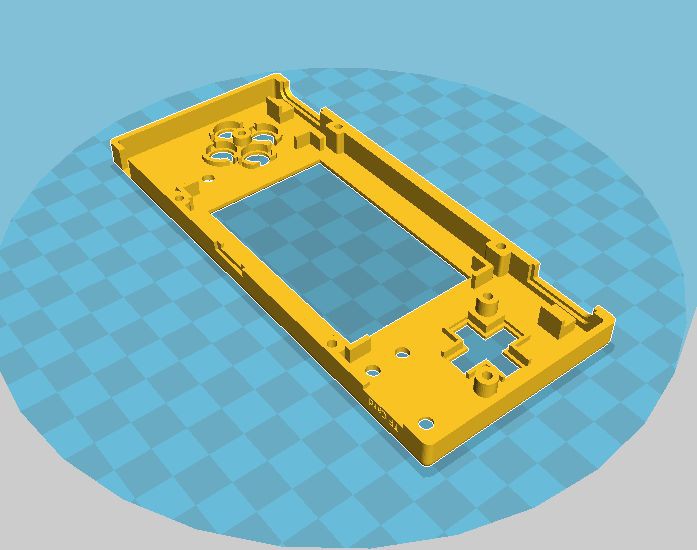
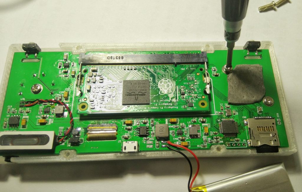
As the circuit is kind of complicated, it is a good choice to do some PCB work. The whole schematic and my own PCB version is upload at the end . If you are intend to use my PCB version, please kindly not remove my logo on the Top_Solder layer. It is better to make your own customization and hand your own PCB file to local manufacturer to make it out because it is really hard to buy all the same parts that I use on my PCB.
After solder all the components on the PCB and tested, the first thing to do is download hex file to the MCU. After that, stick the LCD module on the PCB. The LCD module should be 3mm above the PCB to fit in the case. Use some thick double side tape to stick it on. Then connect the FPC to the connector and insert the CM3L and TF card. DO NOT solder the battery now, plug a usb power source in and boot it up!
Check all the buttons and display. Measure the voltage between the BAT+ and GND, check if the voltage is around 4.2V. If the voltage is OK, unplug the usb cable and solder the battery on. Try the power button.
Put the CROSS and ABXY button in the TOP case, and put the PCB in the case. Use 3 screws to fix the PCB in the case. Add some thick double side tape on the back of all the SKPDACD010 buttons, and stick the battery on it. DO use thick tape to avoid the pins of SKPDACD010 damage the battery. Then stick the speaker to the BOTTOM case. Before close it up, you may need try out all the buttons, check if they works and bounce properly. Then close the case with 4 screws.
Enjoy.
Some trouble shooting tips:
1) Triple check the pin connection of LCD module on the schematic and PCB.
2) Route the LCD signal wires with length constraint.
3) When you are not sure about the power sections, solder and test each section follow the power sequence. 5V first and then 3.3V, and 1.8V. After all the power sections are tested, solder the other components.
4) If the display blurs frequently, try invert the polarity of the PCLK signal by setting the dpi_output_format.
5) If the display is off center a lot, try invert the polarity of the HSYNC or VSYNC signal.
6) If the display is off center slightly, try adjust the overscan settings.
7) If the display is black, try to wait for the system to boot up to the rc.local script. If you need display from the start, try to wire the SPI interface to the MCU and use the MCU to initialize the LCD module.
8) If the display is black all the time, check the initialization sequence again.
9) Feel free to ask any questions here or through email: zhudi_bupt@163.com
RETRO-CM3: A POWERFUL RETROPIE HANDLED GAME CONSOL
In this project, I will use the RaspberryPi Compute Module 3 and a DPI interface LCD to build a ultimate RetroPie game console.
Discussions
Become a Hackaday.io Member
Create an account to leave a comment. Already have an account? Log In.