-
STL files for the case
01/13/2023 at 13:09 • 0 comments -
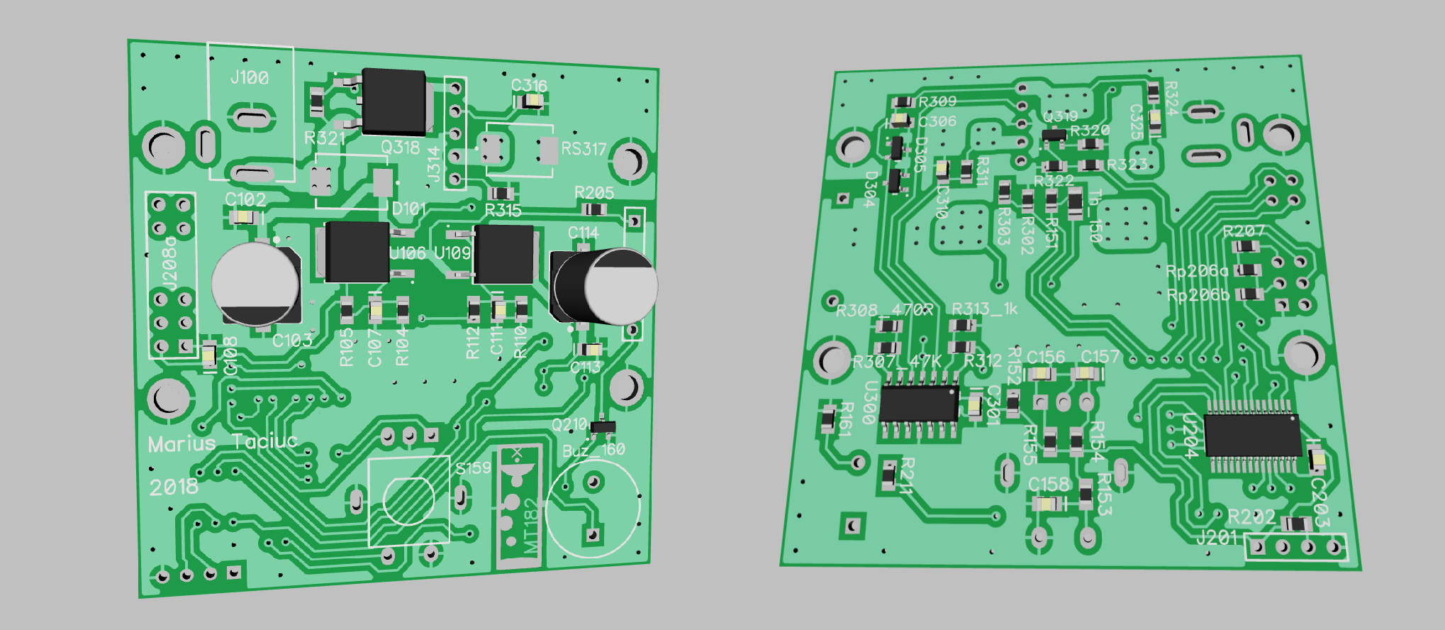
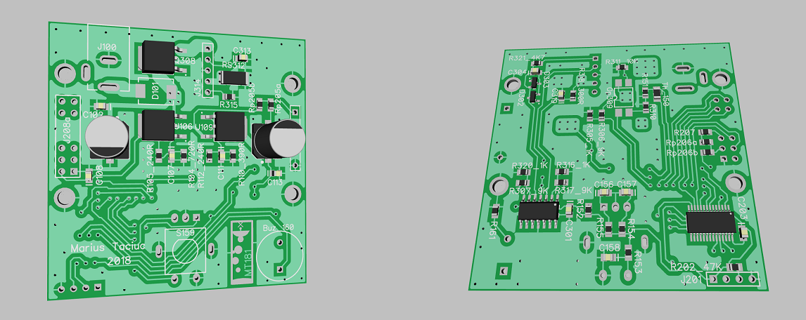
Final layout
07/08/2018 at 23:14 • 4 commentsAs promised, this is the final layout. Check the files area for the updated C3 version.
-
Final firmware update?
06/27/2018 at 12:12 • 0 commentsI managed to add the latest firmware update. After many struggles to achieve all the things that I had in mind, I am happily loading the 4.4 version.
- Better temperature control,
- Fixed a few bugs
- Better human interface
- More intuitive
- Back light control for the C3 hardware
Unless I find some other things that really need changing, I pretty much think of this version as being the last one. Stay tuned for the last update which will be the layout for the C3 hardware. Then I can consider this as being another successfully finished project. About the firmware, I have a final note. I am using IAR Embedded Workbench to flash the MCU. I tried Code Composer and it seems like the code is behaving a little bit different. The compiler takes up much more space for converting the instructions to machine code. Therefore, there are some segments of code that are running at different speeds and the things are not quite fitting together.
-
Solar panel test
06/13/2018 at 13:07 • 0 comments![]()
I made a test using a Xunlight 68W flexible solar panel just to see how this device behaves and it seems like it's working good. This is stretching the idea of portability to a new level. Check the new video for more details.
-
User manual
06/03/2018 at 10:34 • 0 commentsI added the first draft of the user manual in the Files section.
I think this provides new insight about the product itself and explains all the features better. Check the file and stay tuned for updates!
-
Updated firmware and hardware
05/31/2018 at 10:51 • 0 commentsI updated the hardware to version c3 and the software to v3.0. The new hardware uses a P channel mosfet and solves the heating problem. It also has the possibility to control the back light intensity from software. Check the files.
-
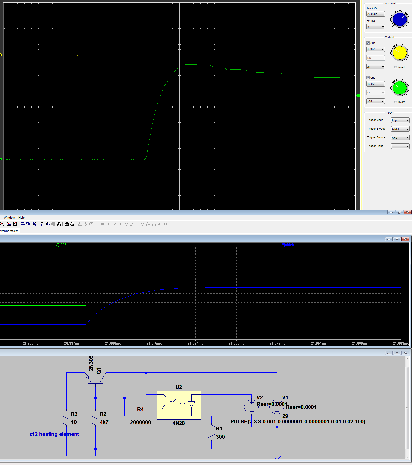
Switching time and snubber?
05/11/2018 at 06:29 • 0 commentsIn the following hardware version I really need to include a snubber for the Mosfet and to make the rising and falling slopes stiffer. I tried different solutions, but it seems like I need to go with a much faster optocoupler. Check the files for the LTspice simulation with bipolar and Mosfet transistor
-
Hakko t12 thermocouple is not Type K!
04/19/2018 at 06:45 • 8 commentsI can tell you that I searched a lot on the internet on every corner I could find and I only came across speculations. No argument or statement supported by some measurements regarding the type of the Hakko t12 tip thermocouple. 80% of the posts out there would say it's type K and the rest will say it's not Type K, but they won't say anything about what is it.
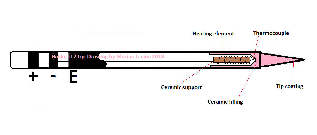
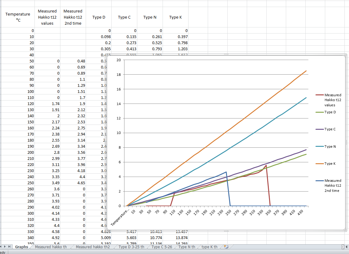
Well, I am ready to support my theory with some facts. First of all, this is how a tip structure looks inside. I took a look inside of one of these tips which paid with it's life for science. Then I draw this as accurate as I could. In what comes the graphs, I made a couple of sets of measurements and compared these measurements with all the known and most common thermocouple types on the market. they look like this:
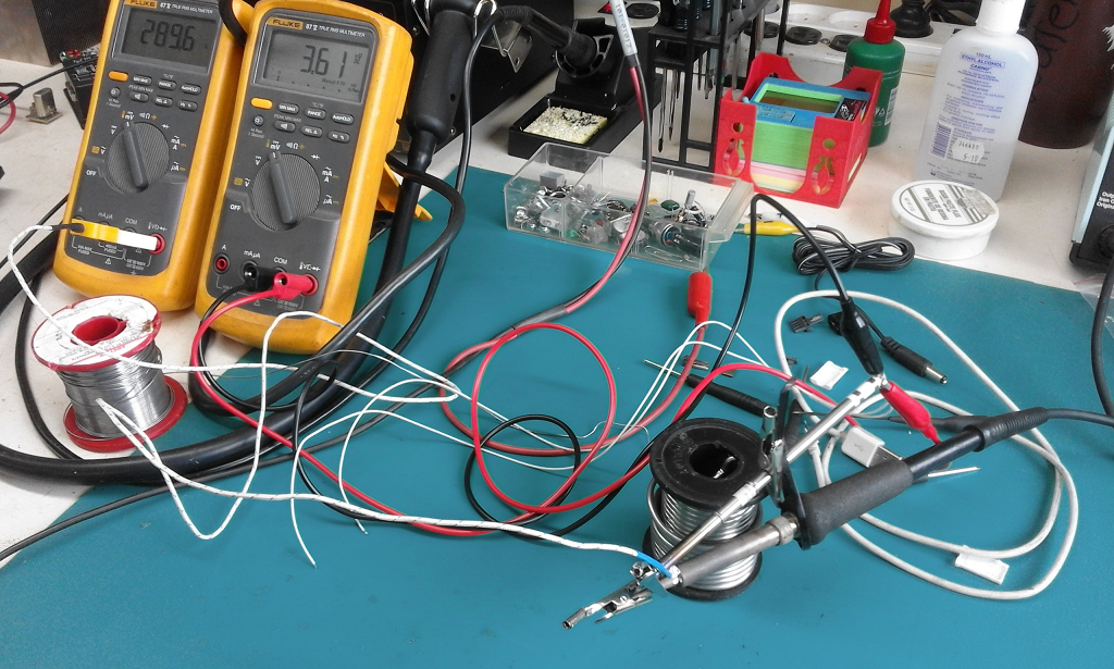
I will post a video to show you how I measured these values, but until then, I can tell you that the 1st measurement was made using another soldering station as a heating element and a Fluke 87-V with original thermocouple as a temperature measuring device. The second measurement was made in a bowl of heated oil. I firs heated the oil to about 300*C and then I placed the Fluke's sensor and the tip in the same bowl of oil. I read the voltage values generated by the hakko tip using another Fluke 87-V set to high resolution mode.
I have to admit that this method is not very precise and you can see this from the two different measurements I made. They came to be so different, because of the temperature gradient in the hakko tip. The higher the temperature difference between the heat source and the environment, the larger the error. This conducts me to the logical conclusion that I must approach the right measured values at lower temperatures. If I look at the graphs, I can see that at lower temperatures, my measurements are overlapping with the graph of the Type C thermocouple. If I had a thermal chamber I would definitely take some more accurate measurements, but until then, I can tell you one thing for sure: this thing is definitely not Type K. Not even close.
I remember reading somewhere on the internet some contradiction related to this. A guy was saying that is Type K and that he measured it and it had around 20uV/*C at some certain temperature. Well that's a misleading statement. Type K thermocouples are having around 41uV/*C at 1000*.
I implemented the 21uV/*C value in software and later on, I tested the system with different values such as 19uV/*C, 20uV/*C and others. I was measuring the tip temperature using a Fluke while testing it and I can tell you that the hakko tip seems to be pretty linear. Moreover, I managed to achieve a less than 10*C difference between the temperature displayed on the screen of the soldering station and the externally measured temperature of the tip. And I expect that the Fluke thermocouple would have it's own mass and act like a heat sink on it's length. Therefore it's good to see the heating element and the core of the hakko tip at a temperature greater with 10* than the tip itself.
It actually makes sense to have the heating element made out of some tungsten alloy rather than nichrome, because the design is airtight and tungsten is cheap. Type C thermocouples are 95%W/5%Re–74%W/26%Re. The heating element is probably made out of 95%W and the other wire that comes form the socket and joins with the heating element creating the thermocouple is probably 74%W/26%Re. Problem solved.
This brings me to blaming these failed soldering station kits again:
I don't know who designed these, but they only have the possibility to set the uV/*C from 41 down to about 30 from the internal menu and this says it all.
-
Added PCB pictures
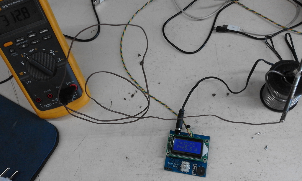
03/26/2018 at 23:07 • 1 commentNow it's the time to keep changing components and to run some tests. As you noticed in the picture, I used a 16*2 LCD until I had the 0802 ones. Check the gallery for all the pictures and stand by for more updates and some software files.
-
Added layout
03/22/2018 at 23:50 • 0 commentsCheck the Files area for the layout files I added today
 Marius Taciuc