-
Starting the RPi
07/11/2016 at 19:27 • 0 commentsSo I have been busy with a lot of things lately (Not with this project :( ). This week it was time to start again.
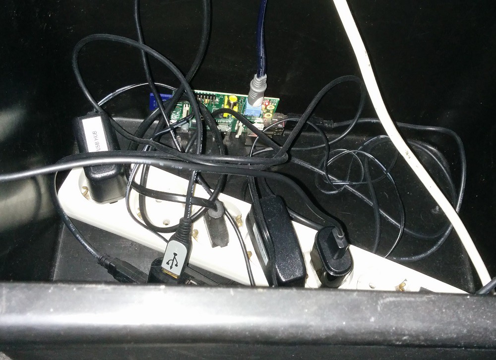
- I have prepared the RPi
- Installed the WiFi driver from http://oshlab.com/esp8266-raspberry-pi-gpio-wifi/
- Fixed a stupid bug in the schematic :( (CH_PD connected to the wrong pin)
- Fixed another stupid mistake :( . I did not close JP7 so the esp did not get any power (Always the first debugging question: is it plugged in?)
- But now I have working wifi using the esp8266 :D
- I also updated the readme so future me knows how to configure everything
So next steps:
- Getting the audio output working
- Testing if streaming internet radio is working
- Install the IMU
- solder a lot of leds
- Create firmware for the teensy to drive all the leds
- ...
-
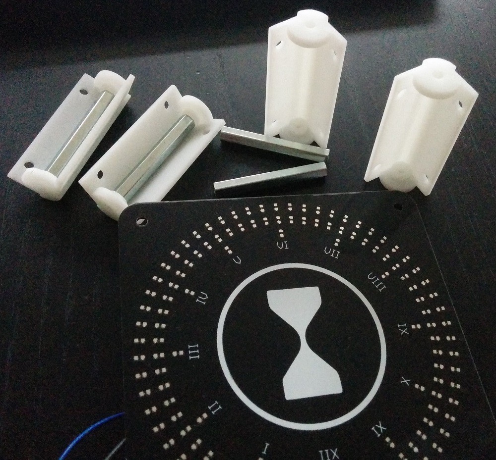
3D prints and assembly
05/25/2016 at 18:55 • 0 commentsThe 3D prints from Dirty 3D printing have arrived!
![]()
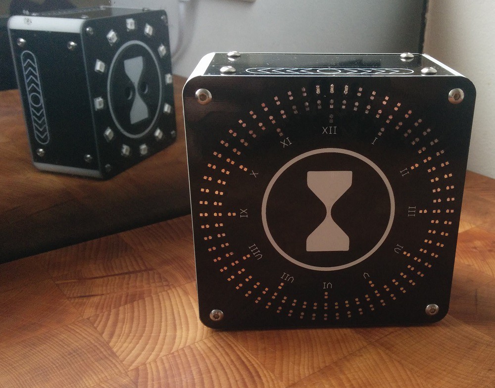
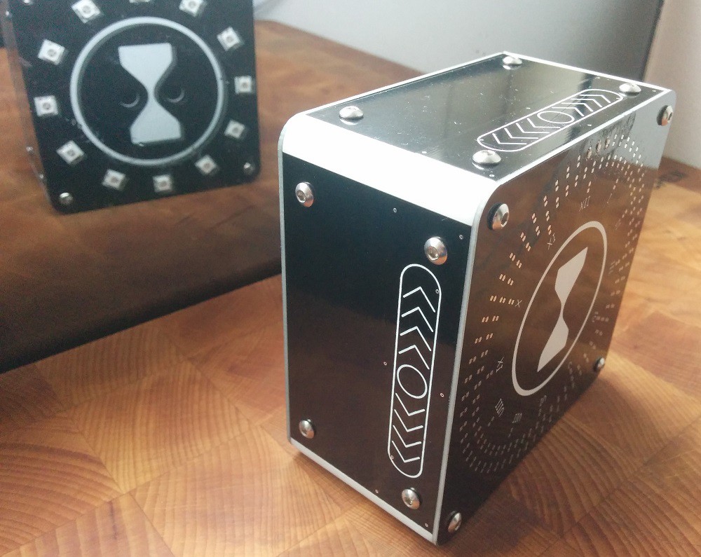
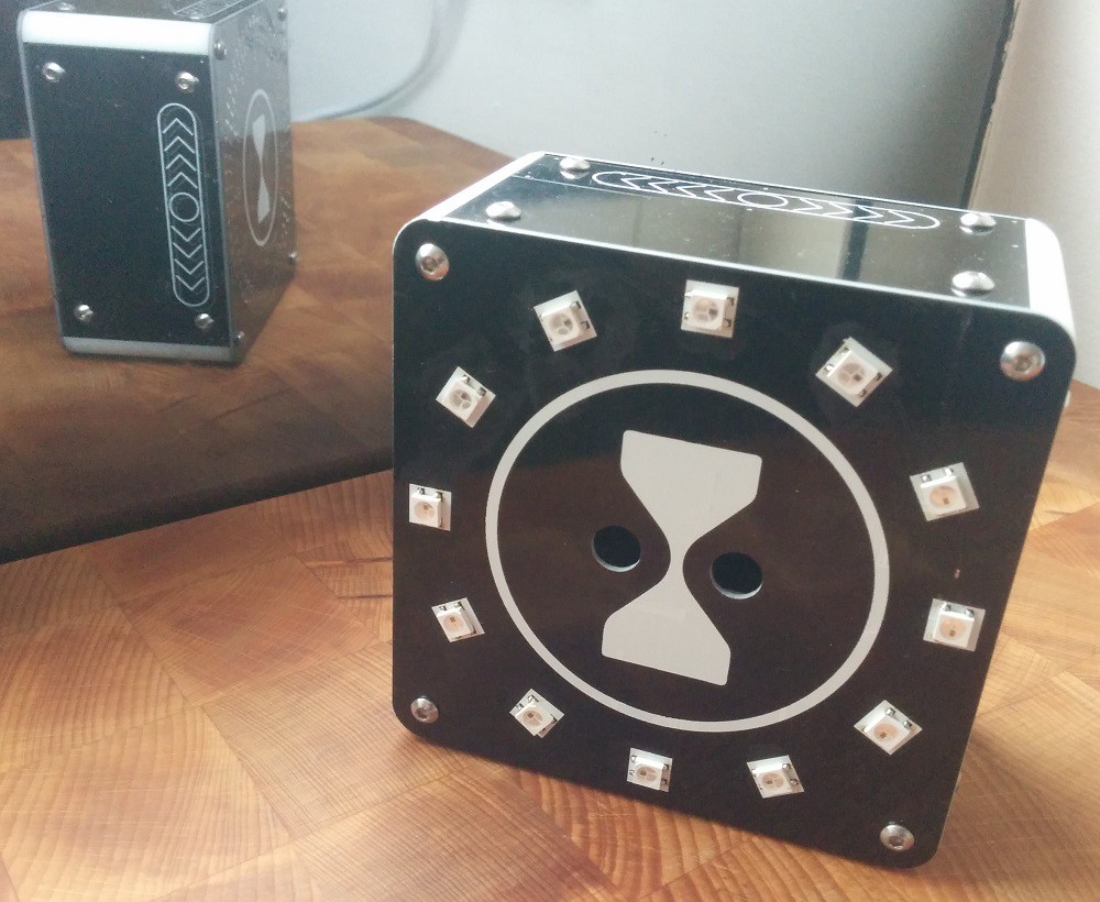
Offcourse I have assembled it. First 3D print ever and it fits!
First the front (clock face). It has a lot of leds and a big touch button in the middle
![]()
Next the sides are capacitive sliders. They are on the four sides. The IMU inside is going to be used to determine which way is up. This way the top slider can always handle the back/wake up light. Left slider the channel and the right slider the volume of the music.
![]()
On the back are 12 WS2812 leds. These are going to be the wake up light. Probably they will also be used as a normal light with the slider
![]()
And Finally the inside. As you can see there is plenty of room. What else can I fit in there ....
![]()
-
Boards have arrived!
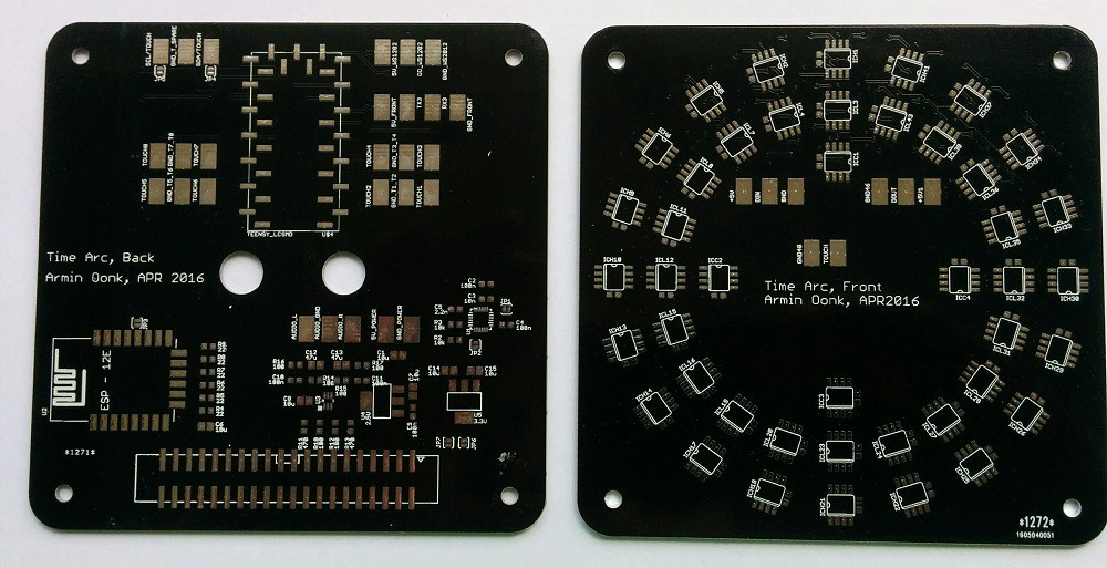
05/15/2016 at 17:24 • 0 commentsThe boards have arrived. I used the experimental website from dangerous prototype. With a very quick delivery in just 9 days! Yes I used DHL shipping but with the low prices it did not really matter too much.
![]()
![]()
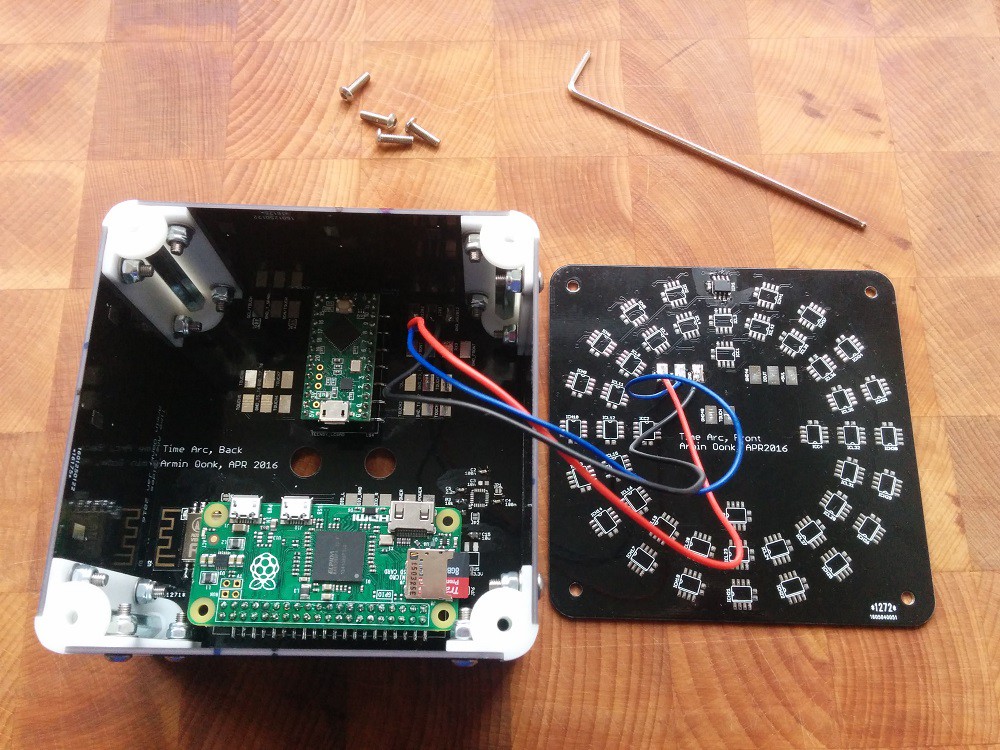
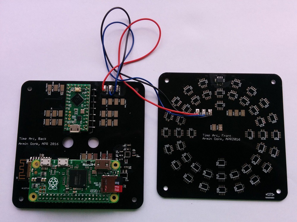
So I offcourse (partially) assembled the boards and tested the leds, which seem to be OK. All the other part stil have to be tested but I also have some other projects running.
![]()
![]()
-
Board designs ready
04/27/2016 at 19:09 • 0 commentsOK I switched back to eagle. Having 6+ years of experience using eagle makes it a lot easier for me to use. Kicad is not terrible software but it still has some rough edges. Also I did not want to invest more time in learning Kicad at this moment.
So the boards are ready. O yeah I also redesigned the front panel. I was not actually planning on doing this right now. But I was trying to see if the idea was even possible and before I knew it the design was finished.
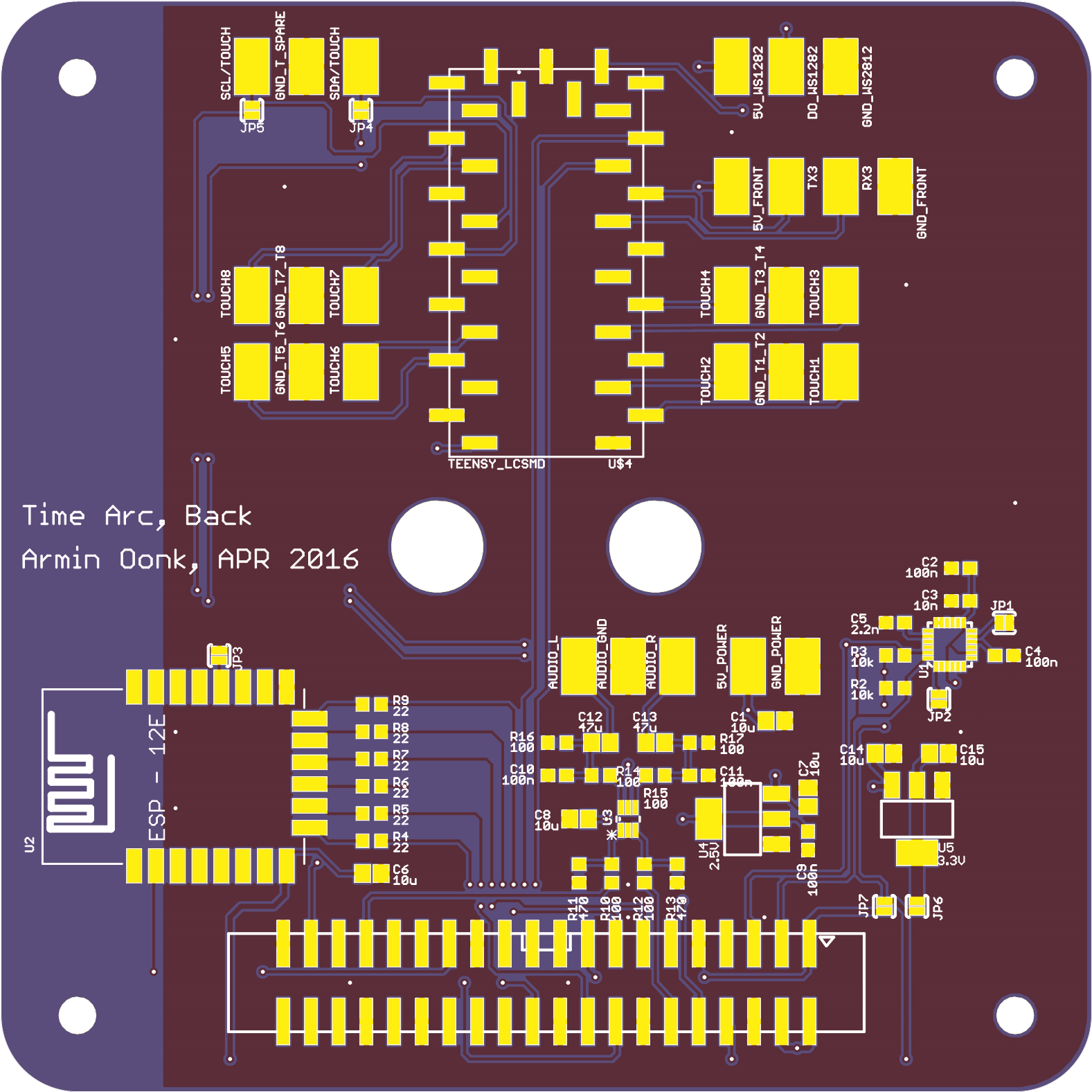
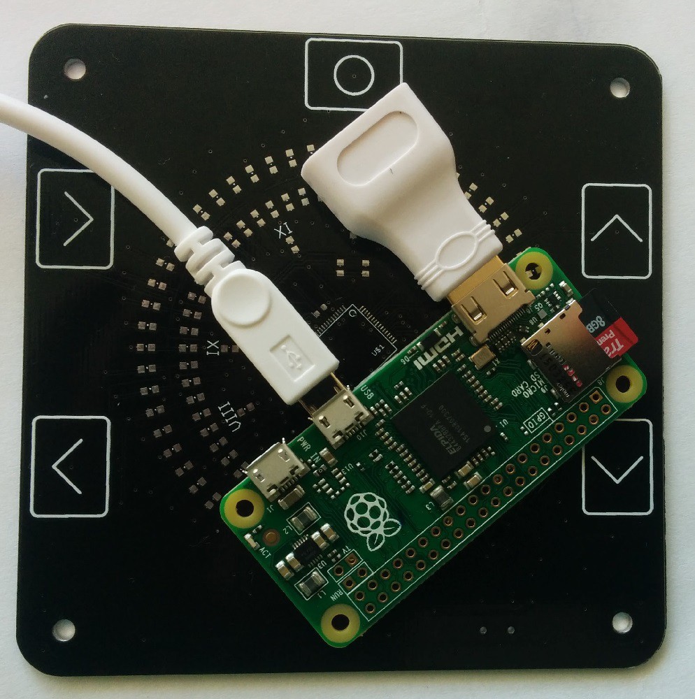
The back PCB has:
- Raspberry pi zero (Audio, IMU reading)
- Teensy LC (Capacitive touch, WS8212 leds)
- ESP12-F as a WiFi for the RPi, idea from: RPi WiFi
![]()
![]()
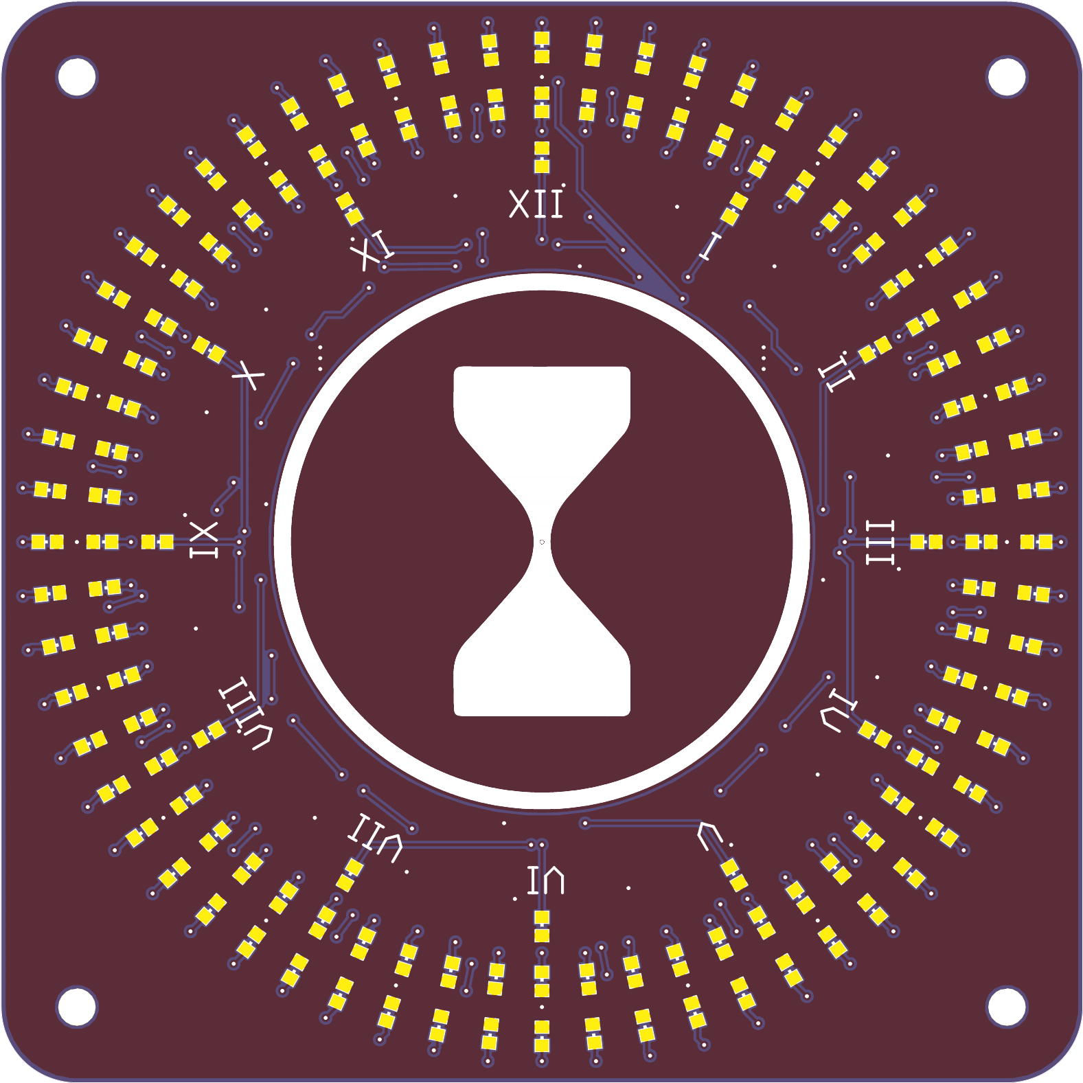
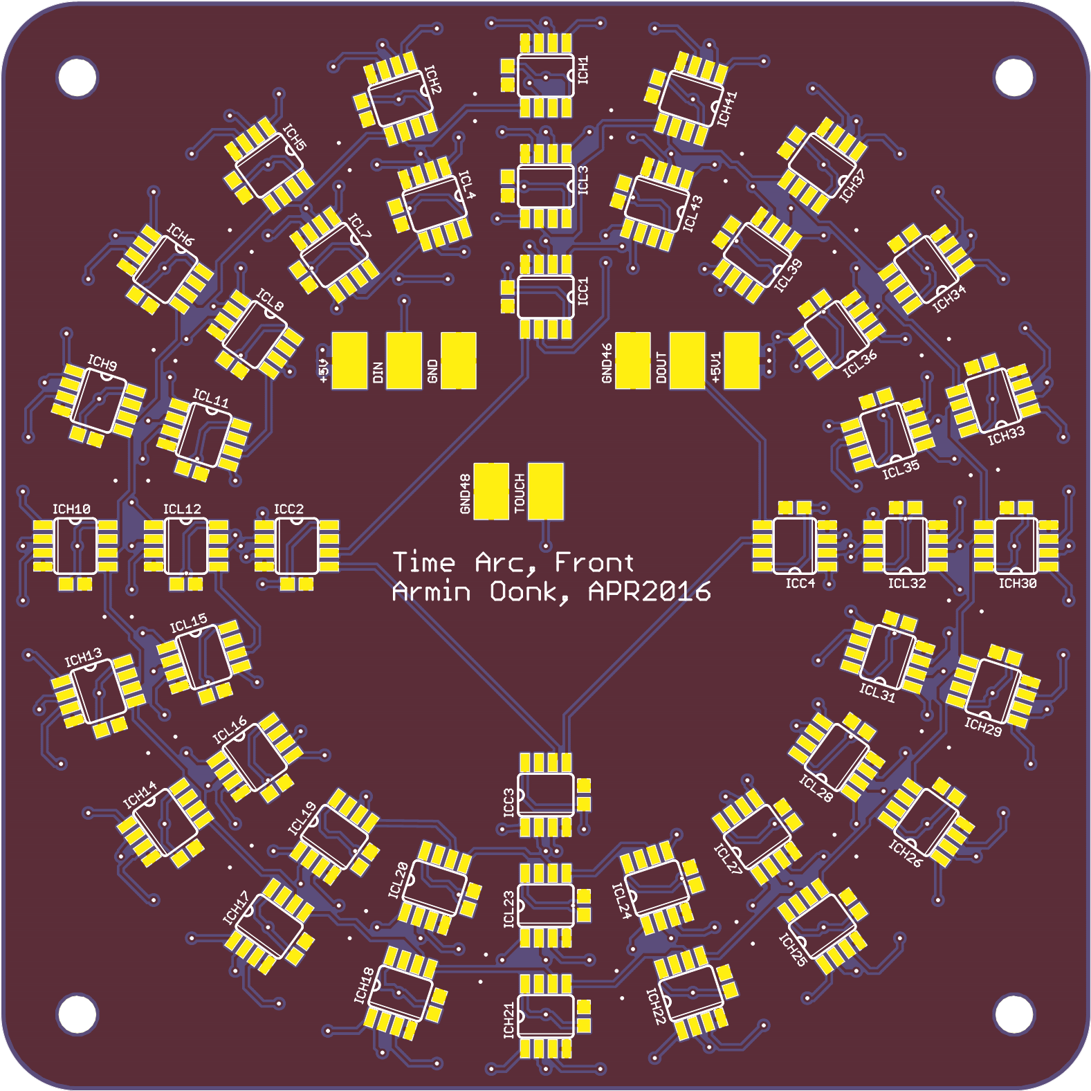
The front has:
- 44 WS8211 led driver ic's
- 132 leds
- 1 big capacitive touch pad
![]()
![]()
I am getting the boards from Dirty pcbs so the only thing to do is wait until they arrive. (OK maybe work on the software a bit)
-
Raspberry pi zero
04/10/2016 at 12:41 • 0 commentsYEAH, finally found a RPi zero online. So I can continue the design.
I have been working with Kicad for the last couple of weeks. Not sure if I completely like it, but it seems to do the job. (I might be biased with 6+ years of eagle experience).
![]()
The schematic is finished and I am starting on the board file. the TOP layer will be on the inside of the enclosure. Most of the components go there. They can not be through hole because it will mess up the outside of the enclosure. On the BOTTOM layer there will be 12 ws8212 leds as a wake up light. There also needs to be an audio jack connector and a power connector (panel mount).
-
Schematic
02/22/2016 at 20:21 • 0 commentsSo I finished the schematic.
![]()
I have implemented:
- Raspberry Pi Zero
- Analog audio out
- Teensy LC
- Capacitive touch interface
- WS2812 wakeup light
- ESP12-E for internet
- USB Hub (mainly backup)
- MPU9150 9 DOF IMU
I removed the audio amplifier. There are a lot of cheap/good alternatives available.
I added the MPU9150 9 DOF IMU. On the current board there is a simple accelerometer, with the gyroscopes on the MPU9150 I hope to get a better attitude estimate. (Also in the future I hope to run everything on the teensy)
-
Enclosure design
02/14/2016 at 19:40 • 0 commentsThis entire project started because I liked some led clocks I found online. For example: http://www.instructables.com/id/LED-Pocket-Watch/?ALLSTEPS
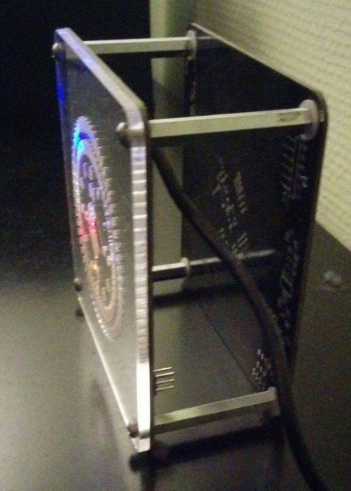
With no real idea on how/if I was going to build an enclosure for it I just used 4 spacer and 2 pcb's to create something. I also cut a 3mm clear acrylics front plate to protect all the leds and other compontents. This is a simple and strong first 'enclosure'. Disadvantages: I can not hide the electronics and the tap function of the accelerometer does not work when tapped on the top.
Since I am still using this project after more than a year, I think it is time to design an enclosure. Since this project started with pcb material it is only logical to continue this material as much as possible. So a couple of months I ago designed the pcbs for the sides. I included a capacitive touch slider on these to improve the user interaction.![]()
Side note: The current capacitive touch buttons are too sensitive. When I wake up (still half a sleep) and touch the alarm clock the channel changes or volume goes up/down.
So now the electronics compartment looks like this:
And before the raspberry pi zero I did not know how I was going to fit everything in a 100x100x50 mm box. (YES I am competing in the Adafruit Pi Zero Contest)![]()
So I still have to design 1 more pcb the back pcb. This pcb will (probably) have:
- A connection for the raspberry pi zero.
- USB hub for future additions and as a backup wifi and sound card
- Audio output (analog) based on the RPi 2 design (Not going for audiophile quality)
- ESP8266 WiFi
- Teensy LC interface (price from my 2015hackadayprice) capacitive touch interface and light controller
- Audio amplifier
- Wake up light based on ws2812
I have started the design for this pcb in KiCad
-
Side pcb's
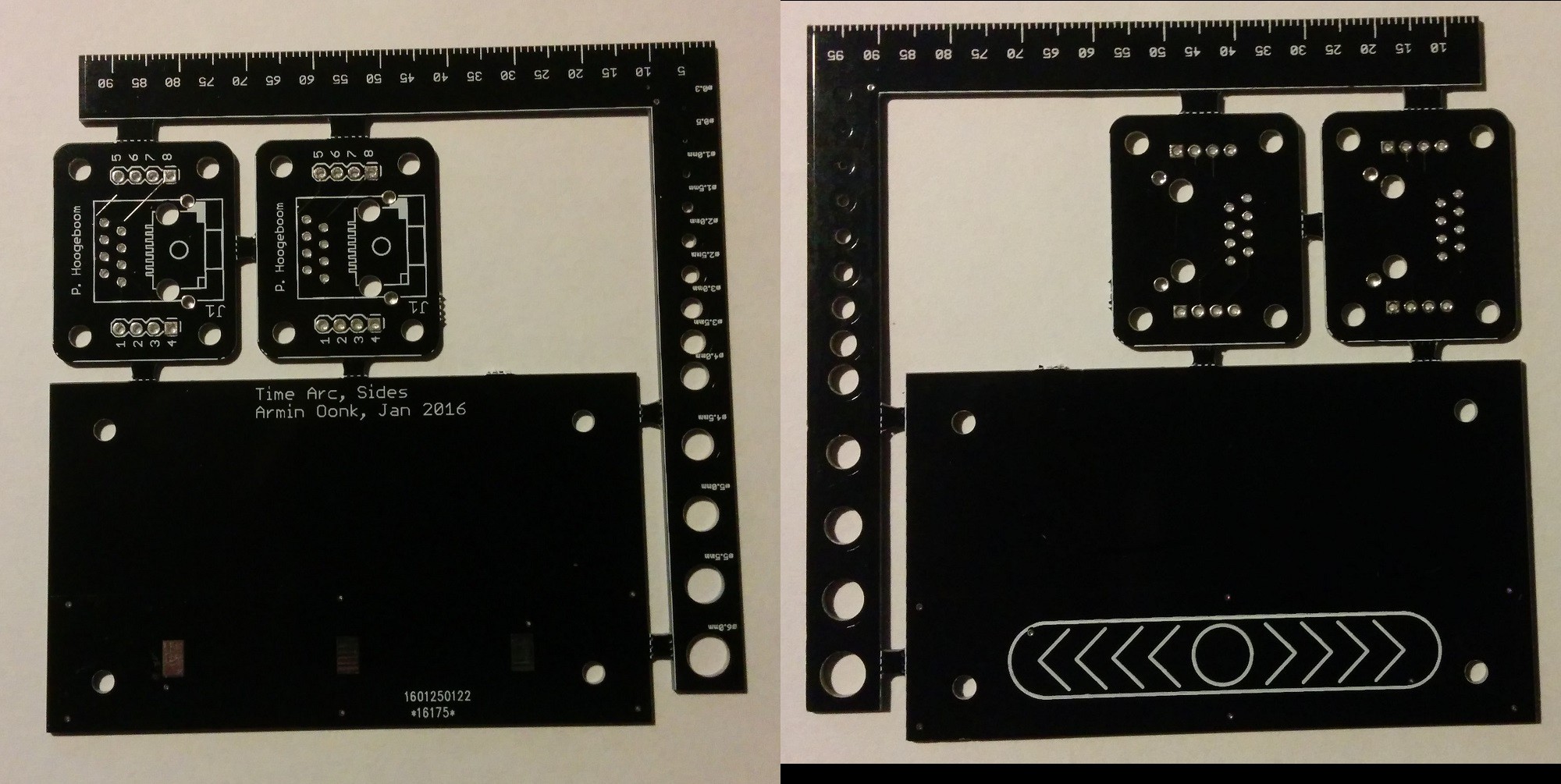
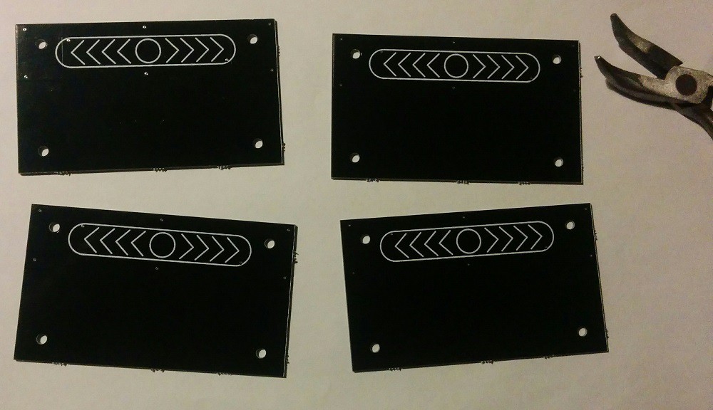
02/08/2016 at 19:52 • 1 commentToday the side pcb's for the enclosure have arrived (together with some other pcbs). On this is a simple capacitive slider. I hope this works better than simple buttons.
Now I have to 3d print the corners so I can assemble the complete enclosure.
![]()
![]()
 Armin
Armin