Voja Antonic
-
Bootloader and Kernel integrated
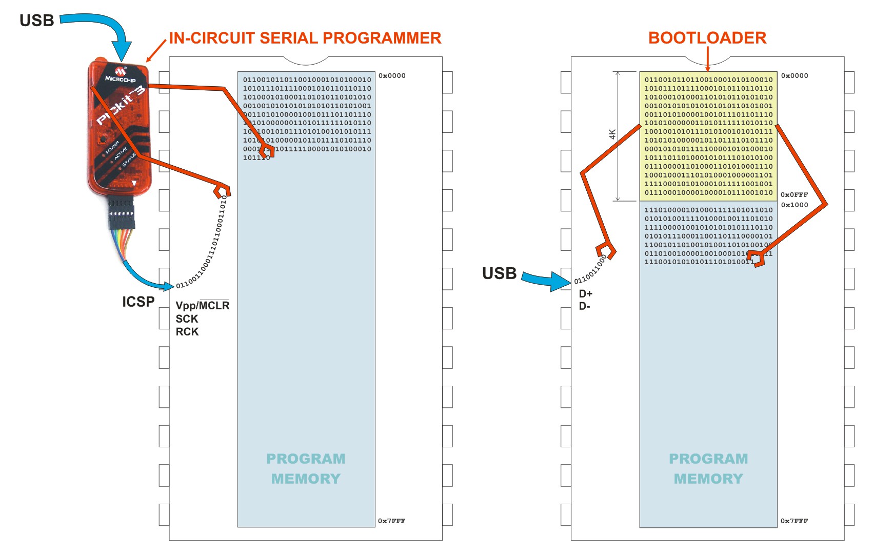
04/01/2016 at 21:19 • 1 commentThe new version of firmware, which shall be official at the Hackaday Belgrade Conference, contains the firmware which integrates Bootloader and Kernel function. It occupies 6 K of Program Memory, so there is 26 K available for user code.
This will make the process of writing the user code significantly easier. Kernel contains the following transparent functions:
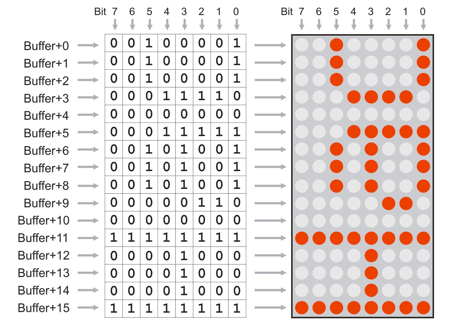
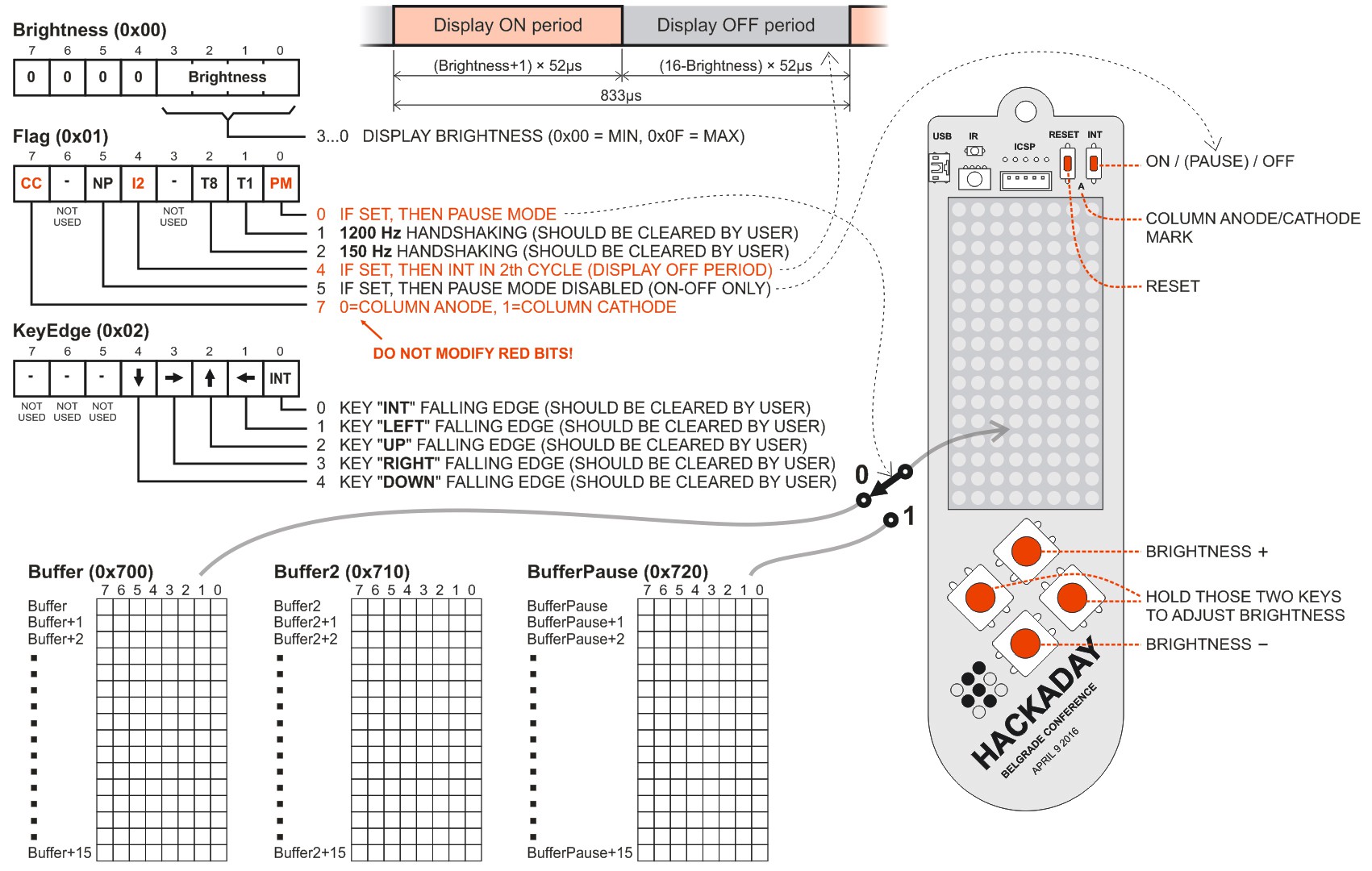
- LED display refresh
- Debouncer and edge detection for all keys
- Brightness high/low service in 16 steps, with physiological linearization
- Pause and Sleep/Wake Up service
- Optical communication service via serial port, with embedded protocol (which includes serial number as recipient's address)There is also Demo Application software, with Moving Message Display, Tetris game and Accelerometer demo software (if hardware module GY-521 is available). This software is not a part of Kernel, ant it will be overwritten at the next software bootloading.
Details are in the updated PDF file Hackaday Belgrade Badge Manual (version 2), which is in the FILES page
-
Some slides from .pptx
03/19/2016 at 10:51 • 0 commentsMy conference talk will cover the basic badge concept and some useful suggestions for badge hacking and the special badge crack.
Here are a few slides from the presentation.
![]()
![]()
![]()
![]()
![]()
![]()
![]()
-
Infrared terminal interface
03/04/2016 at 23:50 • 0 comments![]()
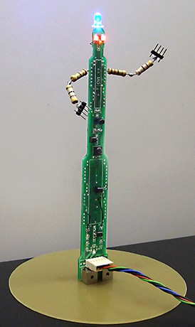
Here's the infrared interface for HaD|Bg badge, which will be exibited and available during the conference. It connects with some desktop PC through RS-232 port, and converts bidirectional serial data signals to infrared, modulated with 40 KHz carrier. There are LEDs which display the current status: red eyes blink each time when it receives bytes from the badge, and the blue hat blinks when PC transmits data via infrared LED.
It will have two functions on the 04.09 happening:
First, everybody will be able to express themselves by entering the name or some other ASCII message in the serial terminal via keyboard, and transfering it to the badge. As the badge is equipped with moving message function, we shall have a hundreds of messages running around.
Second, if you intend to employ the infrared TX/RX during the software hacking workshop, you will be able to test the parts of the program by simply communicating with the desktopćs terminal
In case you wonder about the unusual PCB design - its the leftover of the old project, now equipped with one PIC18F2220 (in the original version, there were two MCUs, but the lower one is empty now). Microcontroller is not too busy - it only generates 40KHz carrier and generates timings for LED blinking during RX or TX. The signal actually doesn't pass through the MCU.
-
Badge + Accelerometer = Fun
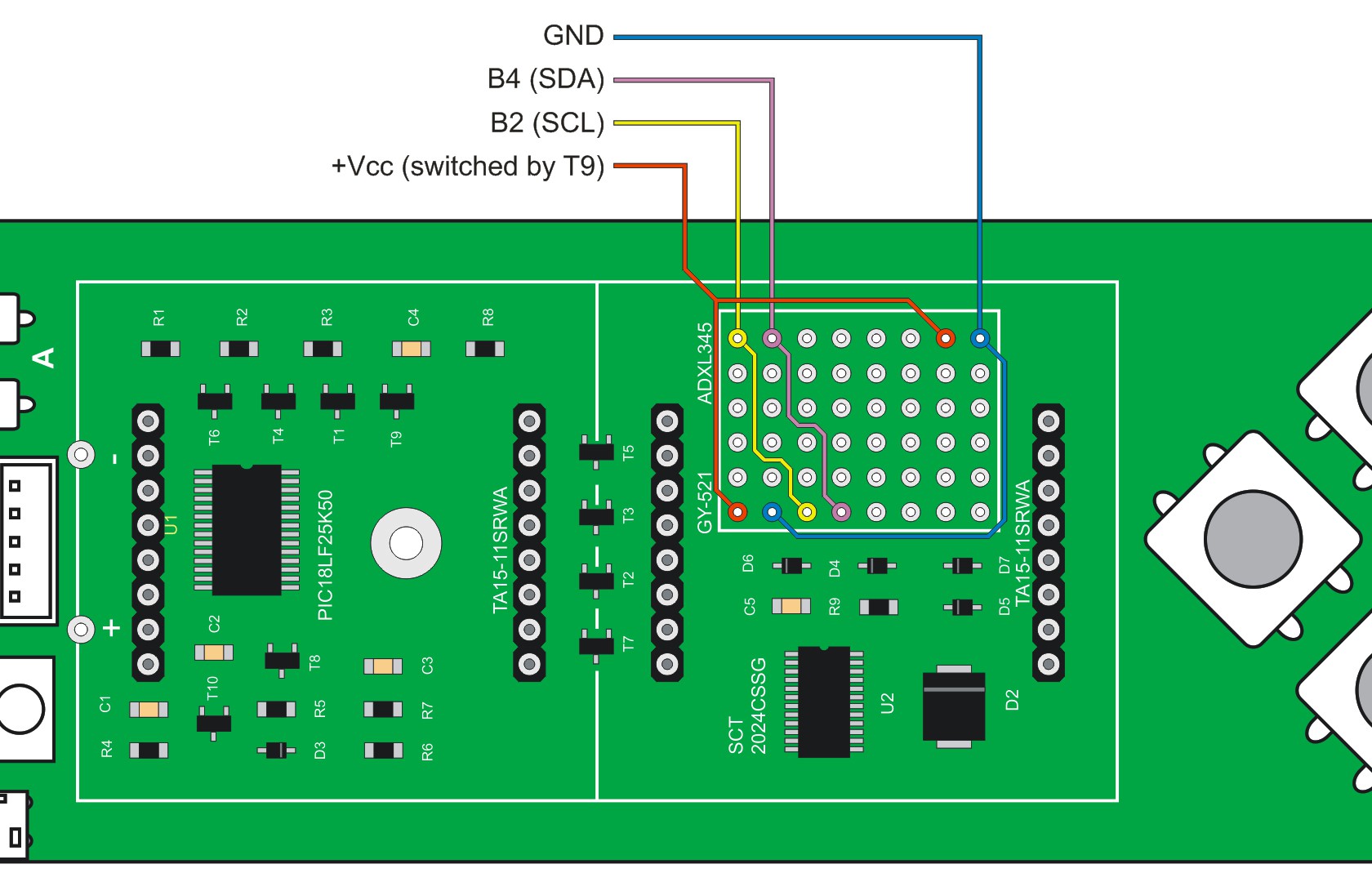
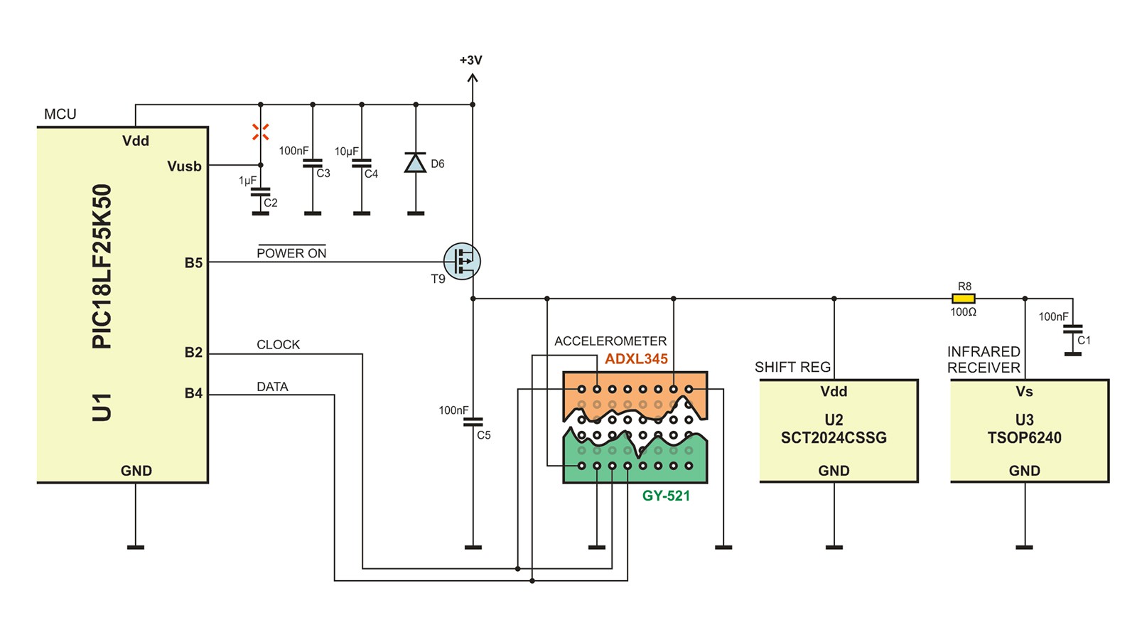
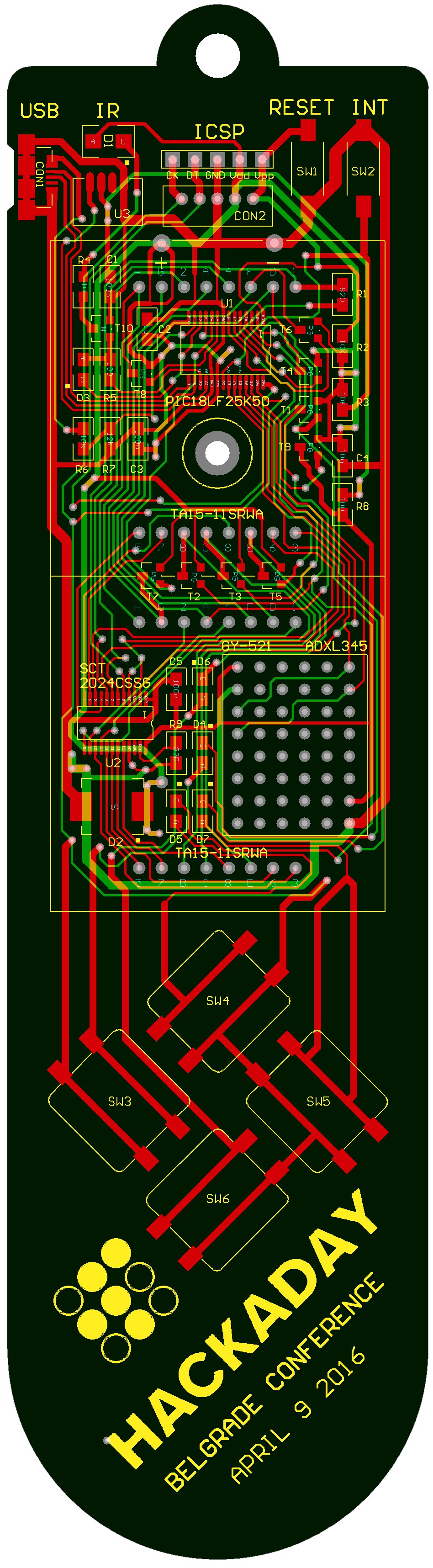
02/28/2016 at 13:25 • 0 commentsHere's the last minute modification on the badge PCB: now it has a place for accelerometer ADXL345 or gyroscope/accelerometer GY-521 module. This is a simple demo:
A lot of Arduino guys know those small modules, they are easy to find and relatively inexpensive (about 3 € here). Here's the screenshot of the final PCB version. The place for accelerometer can also serve as the prototyping/hacking area.
I was experimenting a little with those two accelerometers. First I made the service subroutine, which emulates I2C port by software, and now it can even autodetect the accelerometer type. But my opinion is that GY-521 works much better. I have three ADXL345 modules, and all of them have such a strong noise that 3 or 4 low bits can't be used for anything useful. So, my advice is GY-521. It is about 0.5€ more expensive, but it is not only more stable, but also has gyroscope and temperature sensor.
![]()
-
UART data via infrared
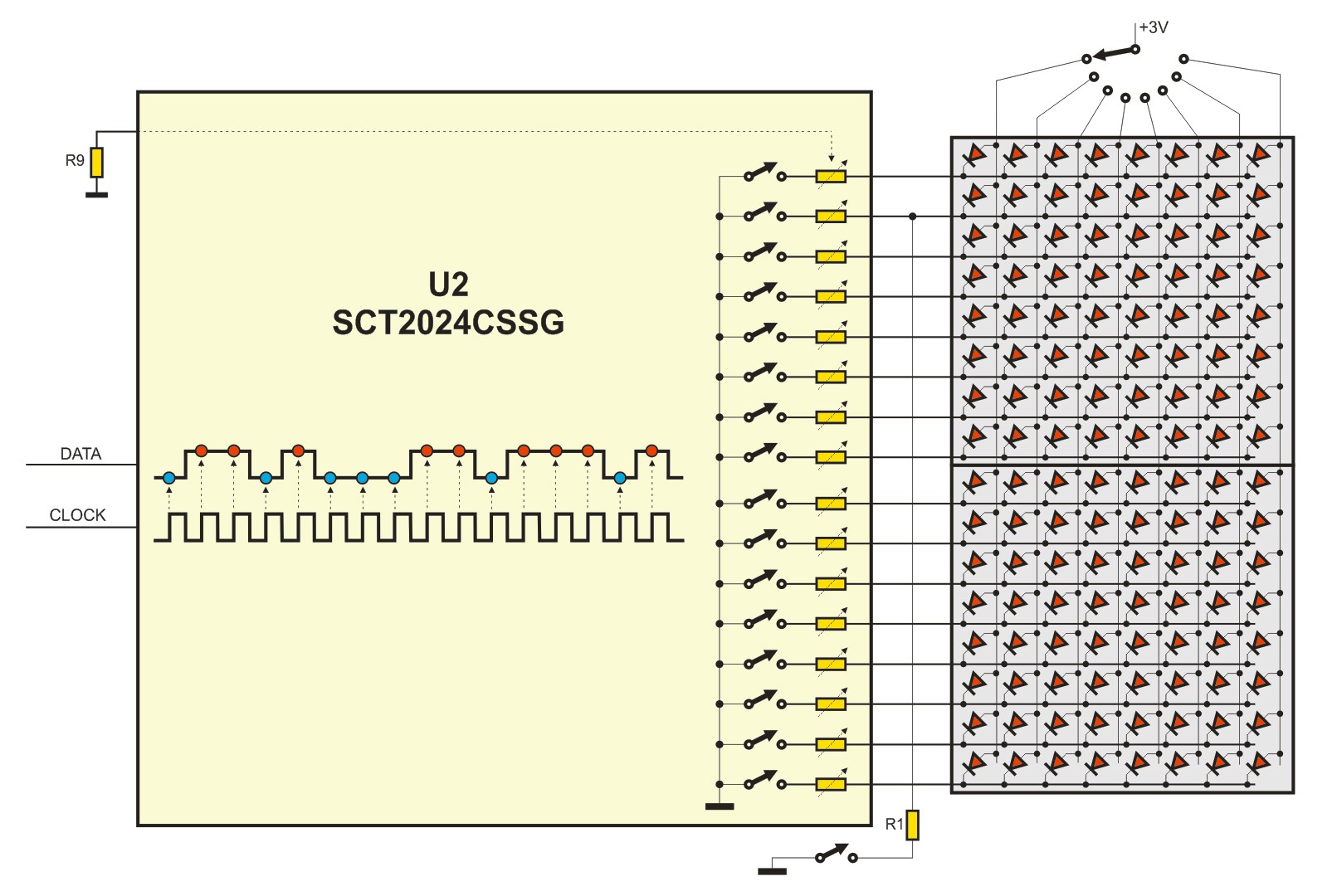
02/07/2016 at 23:13 • 2 commentsThere are several modifications on PCB layout: Anode drivers are not so disorderly scattered over ports A and C - now they are arranged in proper order over port A only. Sink driver SCT2024 outputs are arranged in the similar way. Also, USB mini-A connector is replaced by micro-B, which is much more common today (thanks, @Tom).
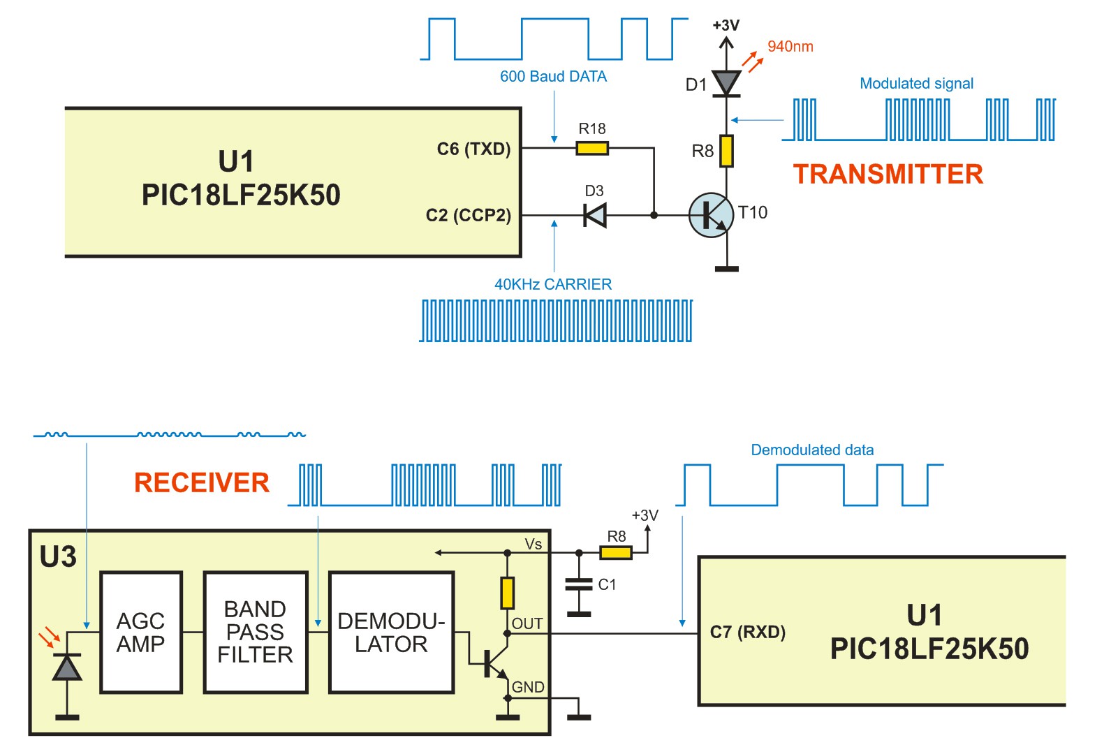
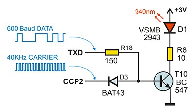
My favorite upgrade is based on one schottky diode D3, which enables semi-duplex serial communication over 940 nm infrared channel. In the first version, there was IR LED and IR receiver TSOP6240TTCD, with contains photodetector, AGC preamplifier, 40KHz band-pass filter and demodulator. You were supposed to apply PCM signal to infrared LED and to pick data by the receiver at the other side, but it consumes 100% of processor time and disables LED multiplex refreshing. But if you use UART to transmit and receive data, you will have the undisturbed display all the time.
The only problem is how to apply 40KHz carrier to infrared LED. You could use external AND gate to do so, but it is much simpler to use the diode which modulates the driver. This carrier can be permanently generated by Output Compare Module, so the complete communication is obtained using internal MCU peripherals.
![]()
With such a low carrier frequency, you can not obtain too high data rate - don't even try (at least with TSOP family) to get more than 600 Baud, which is 60 bytes/sec. But this is a small MCU, with very limited data memory, so you are not supposed to transfer megabytes of data. You will probably transmit and receive some short text for moving message display or your business card details, so one of two seconds will be enough.
I was experimenting a little, and results are quite satisfactory. It is very easy to obtain the good data transfer in one room, even when transmitter and receiver do not 'see' each other, especially if the walls are white.
Badge for Hackaday | Belgrade Conference
I have the honour to design the badge for Belgrade Conference. Here it is! Voilà!