Kn/vD
Kn/vD-
New updates and video
01/29/2017 at 22:37 • 0 commentsPosted a new video and update in the Facebook group: https://www.facebook.com/groups/1190587984388833/
Check also Youtube for the new videos: https://www.youtube.com/channel/UCqTtNn7b951O1GqkDLMm4jg
-
Unprogrammed PIC32
01/05/2017 at 16:31 • 0 commentsIt looks like some people have received ELLO systems with blank PIC32 chip. This is something that wasn't supposed to happen since I explicitly ordered pre-programmed chips from Microchip Direct. No idea what is the reason for that and apologise if that has happened to someone.
The good thing is that the system can be programmed easily with Pickit3, ICD3, or some other compatible programmer. I have released the most current HEX file for ELLO 2M (not 2M²!) in the project's page on GitHub: https://github.com/knivd/ELLO-2M/
The file is called "MicromitePlus_ELLO_2M.hex".
On the expansion connector there is access to the PIC32's programming lines. Connect the programmer's data line to the pin marked "PGD", the clock line goes to "PGC", and the reset line to "MCLR" (not "MCLRK"). Connect a wire from the programmer's ground to one of the ground pins on the connector. Do the same with the 3.3V line.
Switch the system on and it should be ready for uploading the hex into the chip. Reset it after programming and everything should be working fine.
-
Facebook group
01/02/2017 at 15:57 • 0 commentsAll owners and supporters of ELLO are welcome to join the new Facebook group: https://www.facebook.com/groups/1190587984388833/
-
ELLO 2M assembly including keyboard patching
12/28/2016 at 18:24 • 0 commentsPeople asked me how to assemble the keyboard. I am planning to shoot a new assembly video as soon as I can, but until then...
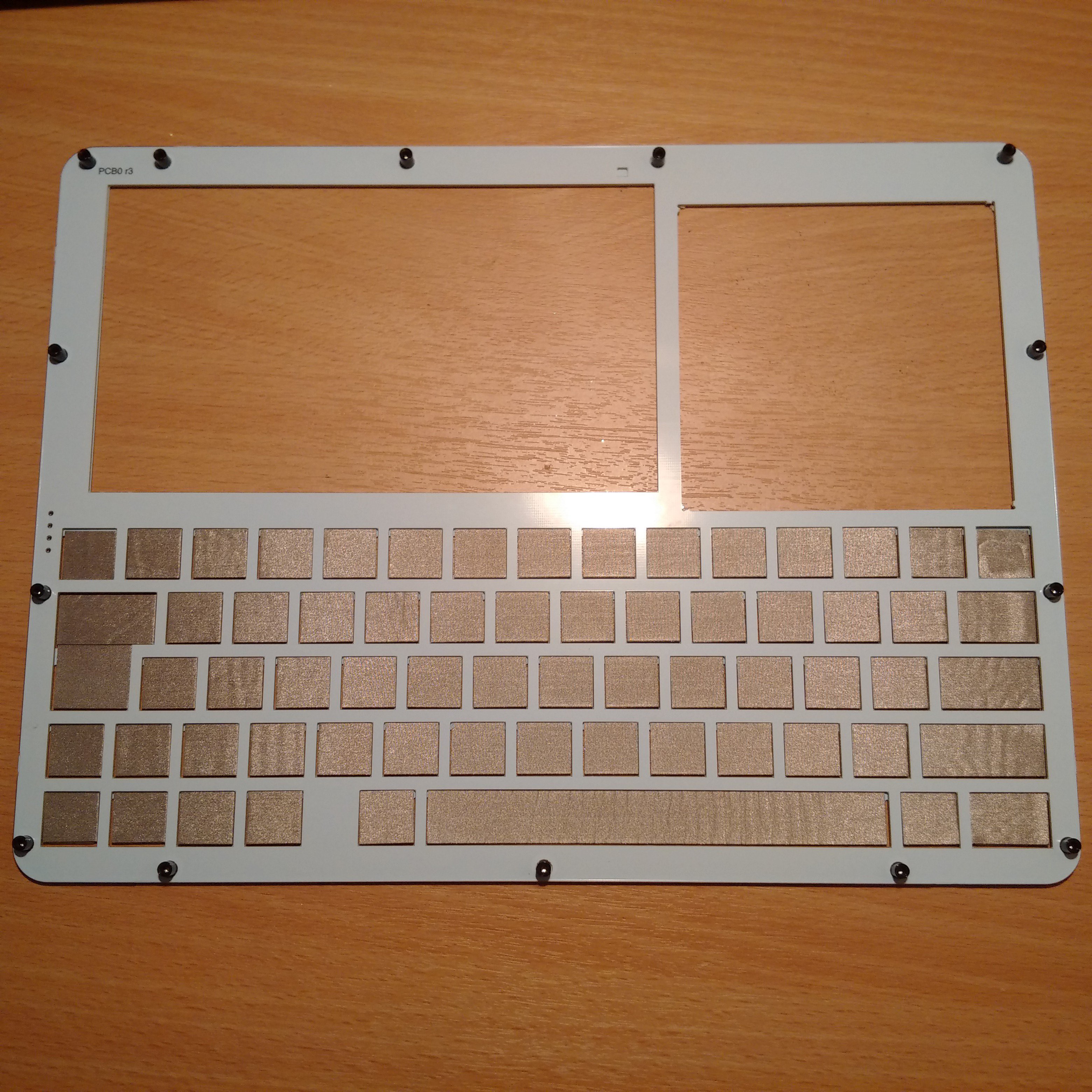
The self-adhesive pads supplied with ELLO are mean to go on the back side of the front board (called Panel). The assembly of the machine ALWAYS starts with attaching the fourteen standoffs to the front panel. Make sure you also remove the lid covering the prototyping space. You can either carefully snap it off, or cut the holding pieces using sharp cutters.
The place the panel face down (the standoffs will tall up), and start inserting the other PCBs in thus formed frame. The first one to go next is PCB0. Just like with the panel - if there is a lid covering the prototyping space, just snap it off or cut. Round up the remaining stumps a little bit, if necessary.
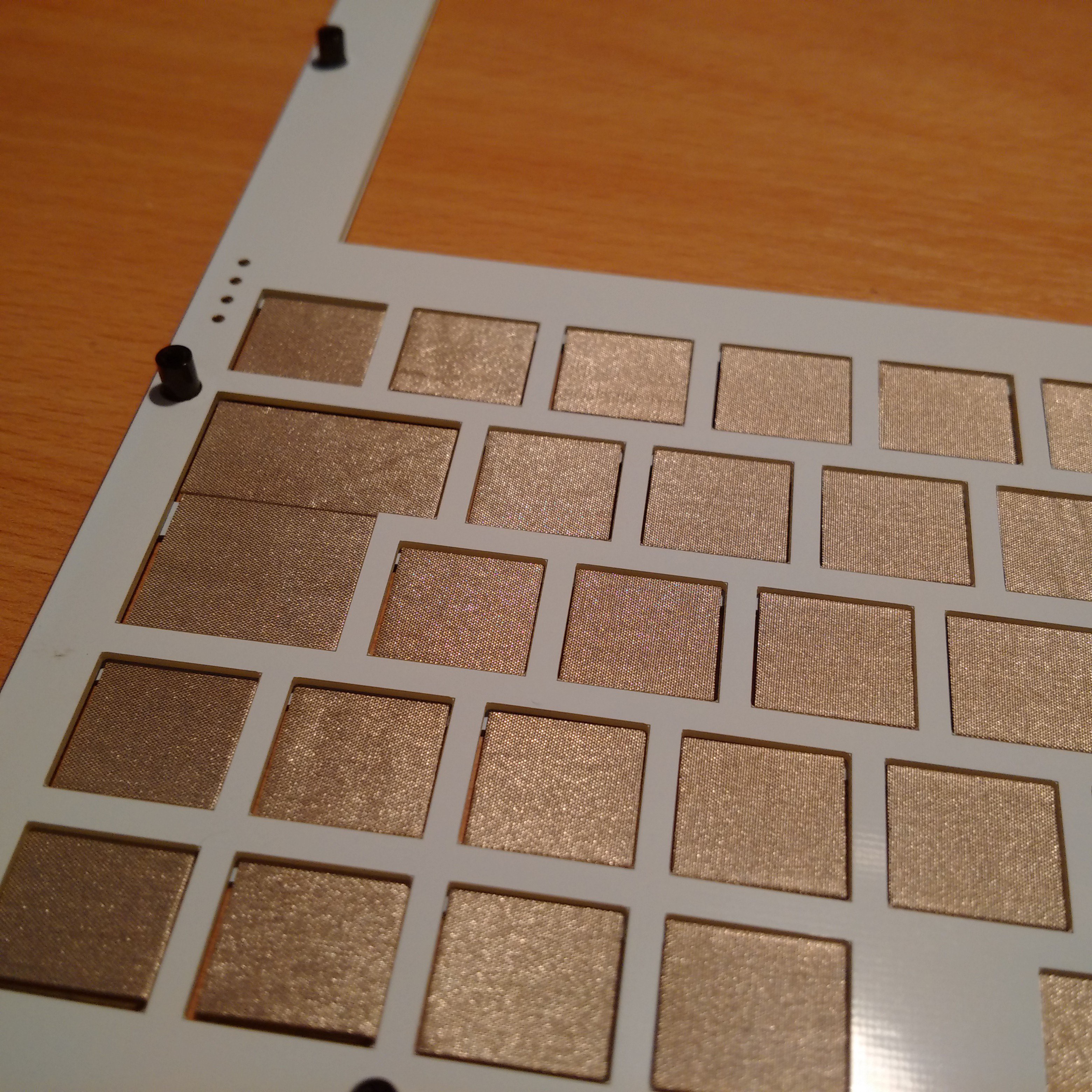
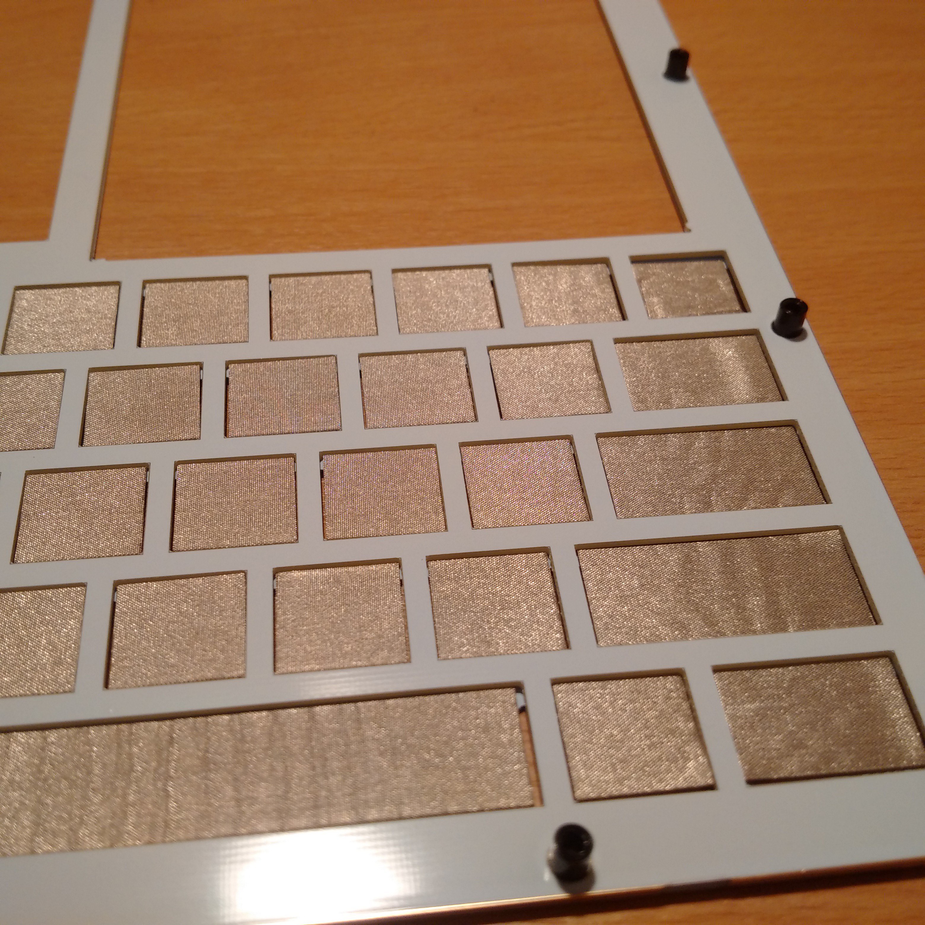
When PCB0 is in the stack, NOW is the time to put the patches. Carefully stick all of them in their places using the top line as reference.
Here is how the frame looks after the operation
![]()
![]()
![]()
Again, use the top line as reference, i.e. insert a patch into its frame until it hits the top and then stick. Thus you will guarantee that the keys are moving freely in their frames.
After patching the keyboard, the next to follow is the computer's main board - PCB1. Place it face down (components must be facing up).
Next - install the display panel face down in its place, and connect it to the connector on PCB1. Stick one of the two supplied round 3M double-sided adhesive patches on the back of the LCD (don't remove its top cover yet).
Stick the second 3M patch somewhere in the in centre of large black area marked for the battery. Remove the top cover as well. Then connect the battery (make absolutely sure that red wire goes to the contact marked '+', and black wire goes to the contact marked '-'). Then carefully stick the battery on the 3M patch in such way that it does not extend over the boundaries marked with lines on PCB1. Tidy up the battery wires so they don't go over the display cable, but around it. With poor assembly you might experience poor picture on the screen as well due to noise, so this is pretty important, actually.
Now install PCB2 again face down. The prototyping sockets must go in their spot. If they can't, that means there is a stump remaining on PCB0. Round it up a bit more and then install PCB2.
PCB3 follows next.
Now it is the time to remove the top cover from the 3M path that is already stuck on the back of the LCD. But don't do that yet, and do this little trick instead.
Install the final PCB4 and screw in the bottom two corner screws so it is fixed in its place. Now bend the top side slightly up to reach under it and remove the top cover from the 3M patch which is on the LCD. Carefully release the board back in its place and screw in tightly all screws.
Your new ELLO 2M is ready to dance.
-
First MMBasic Addendum document for ELLO 2M
12/26/2016 at 14:03 • 1 commentFirst, Merry Christmas to all!
These days I finally had some time to sit and type this document which was long overdue. It is not a full MMBasic manual (those have already been written by its author), but focuses more on the additions on ELLO from user's perspective. I will keep updating this document when I can with the hope that one day it will become a full book for ELLO. If anyone else is interested in helping as well, please let me know.
The file is now in the project's GitHub repository: https://github.com/knivd/ELLO-2M
-
Problem solved (so it seems)
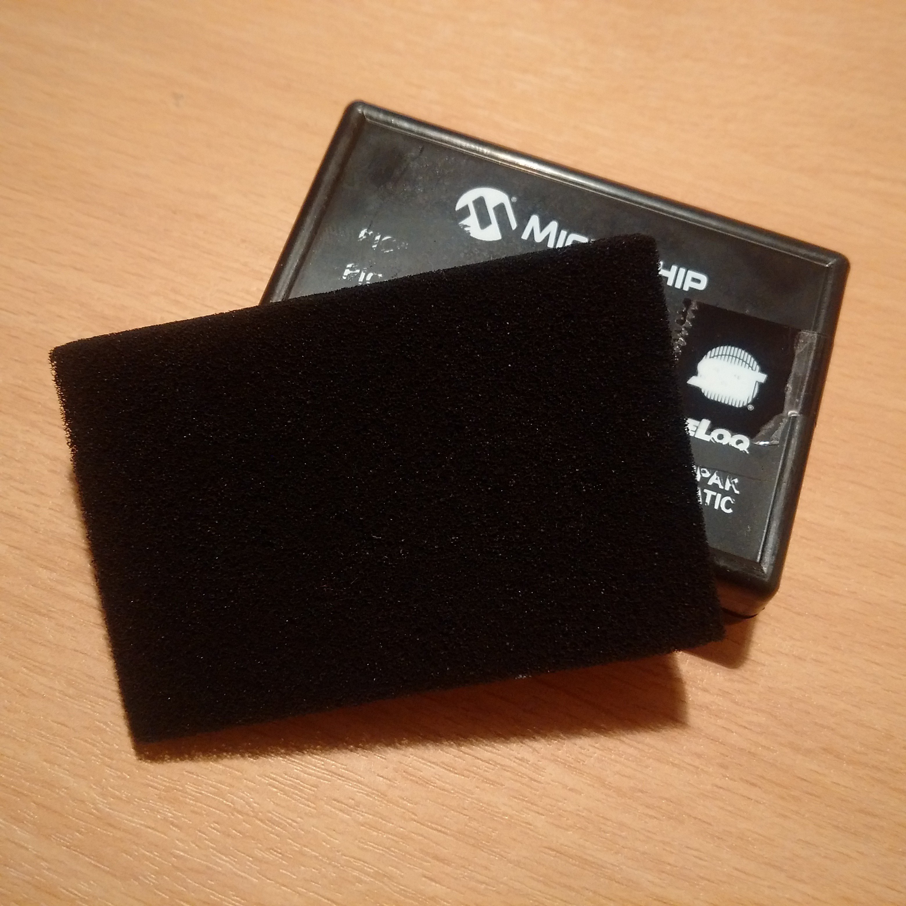
11/17/2016 at 20:36 • 1 commentIt looks like things are not as bad as they looked a few days ago when I discovered the issue with the soldermaks in the keyboard combs. Have been thinking about solutions and tried Velostat (unsuccessfully). There is of course always the option for chemical treatment but I wanted to see first if there is some more user-friendly way. So the good old Microchip came to save the day once again :-)
Just received from them a box with sample chips for unrelated project. The chips have no connection here, but the box caught my attention, and especially the black foam inside.
![]()
So I took the scissors and cut two pieces to fit into the key holes in the PCB0 frame board. The miracle happened - the keys worked perfectly fine! In fact so well that I started feeling sorry that I was so quick to revise the board, and even considering whether to make this the standard way for building ELLO keyboards.
Obviously now the challenge in front of me - to identify where to buy this foam and more especially to have it with the right thickness (0.5-0.7mm) and cut into small square and rectangular pieces as per given specs. Searching and welcoming any information about it.
Getting really close to the finish now...
-
No luck this time...
11/12/2016 at 21:03 • 10 commentsWell, it's time for the first bad report... :-(
Received the production samples. Excellent build. In fact so much excellent that it has created a problem on it own.
In the earlier prototypes I used to work with a different PCB factory which had more limited production capacity and less precise equipment. The result of that - working prototypes. This time the new factory has equipment which is apparently much better and has managed to run soldermask between the teeth of the keyboard comb pads. Result - keyboard not working unless some other techniques are used, such as additional rubber pads, etc. The reason for that is because the soldermask is taller than the exposed copper in the pads and the panel contacts can't create the needed short in the comb. Grrr... :-(
I have fixed the PCB file now to force soldermask expansion (should have done that long time ago!), but now the big question in front of me - what to do with all those first batch manufactured systems with damn non-operation keyboard combs? Trying to think of a quick solution to patch them so people can receive them sooner. So far my ideas are circling around additional self-adhesive conductive rubber pads (tried them with success), or some sort of thin elastic conductive sheet to stick under the keyboard panel (no idea if such thing exists at all).
It is very frustrating problem that needs a quick and clever solution...
-
Release samples ready
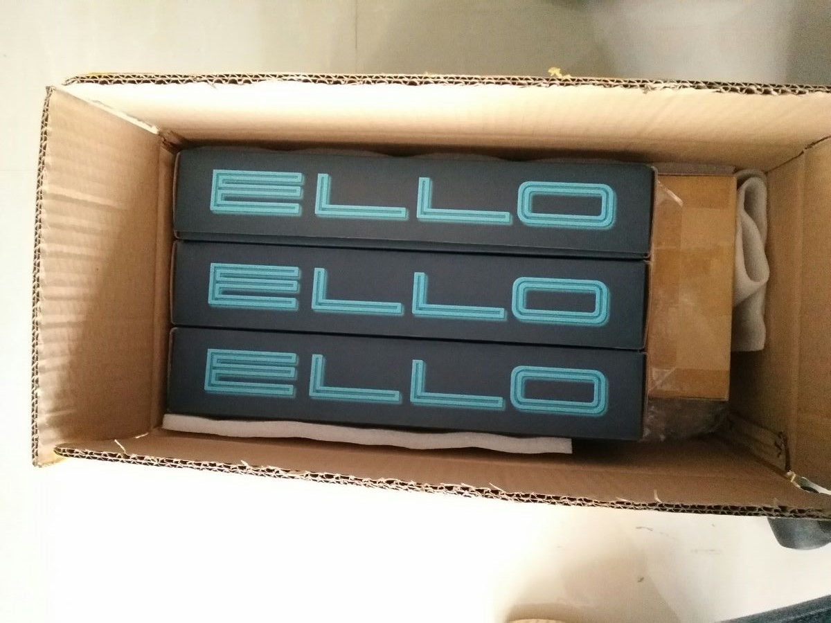
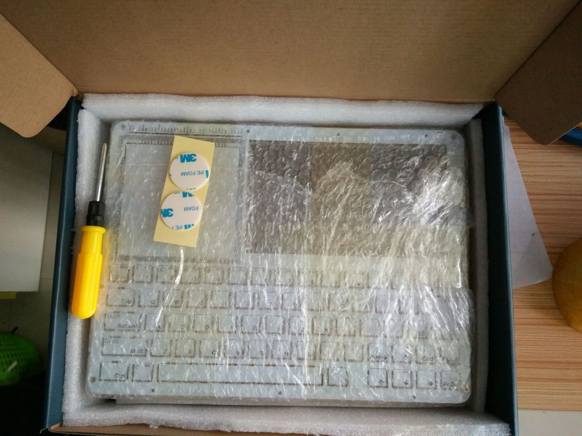
11/06/2016 at 11:15 • 3 commentsThe first three fully manufactured samples are on their way to me from the factory.
To make everyone's life easier I have also added in the kit a small screwdriver and two self-adhesive pads to keep the LCD panel and the battery securely in place. Obviously a pack of screws and standoffs as well. The battery now is wired with a small 2-pin connector, so it won't be needed to be soldered making it easier for assembly by users with no soldering equipment or abilities.
Once I verify and confirm these three systems (will probably publish a new YouTube video soon), people will start receiving their ELLO 2M systems.
Maybe should put together a one-page printed instruction for assembly to be included in the box as well... Ugh.
![]()
![]()
-
License update
10/09/2016 at 14:25 • 5 commentsThis log is probably a little overdue and people already know this, but in case anyone has missed it - I have managed to negotiate the licensing conditions for MMbasic for ELLO. So no more issues on that front, whoohooo!
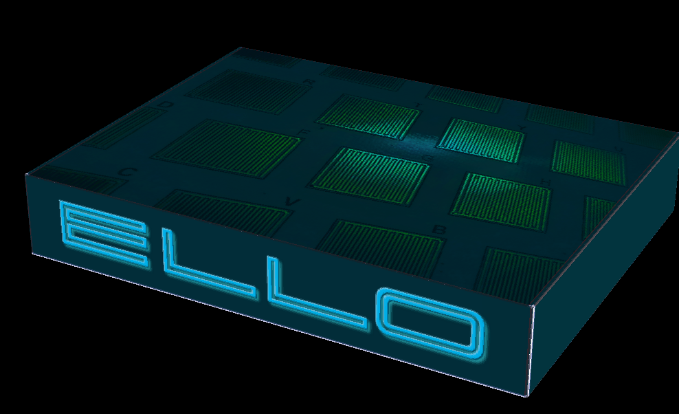
Ah, did I mention the packaging carton box? Yes, there will be one. The design is probably slightly simplistic and controversial, that's the way I like it to be :)
![]()
-
Shortlisted in Elektra 2016 awards
09/13/2016 at 11:27 • 5 commentsThe ELLO 2M project is in the final shortlist stage for the annual Elektra European Electronics Industry Awards 2016, which is due in December: http://www.elektraawards.co.uk/elektraawards2016/shortlist-2016
It is listed as "Yellow Beak Computer Ltd" in the "Educational Support" category. Among the six finalists it is the ONLY entry which is NOT coming from a large corporation, and I consider that as I great recognition for the project.