 Kevin Neubauer
-
1Step 1
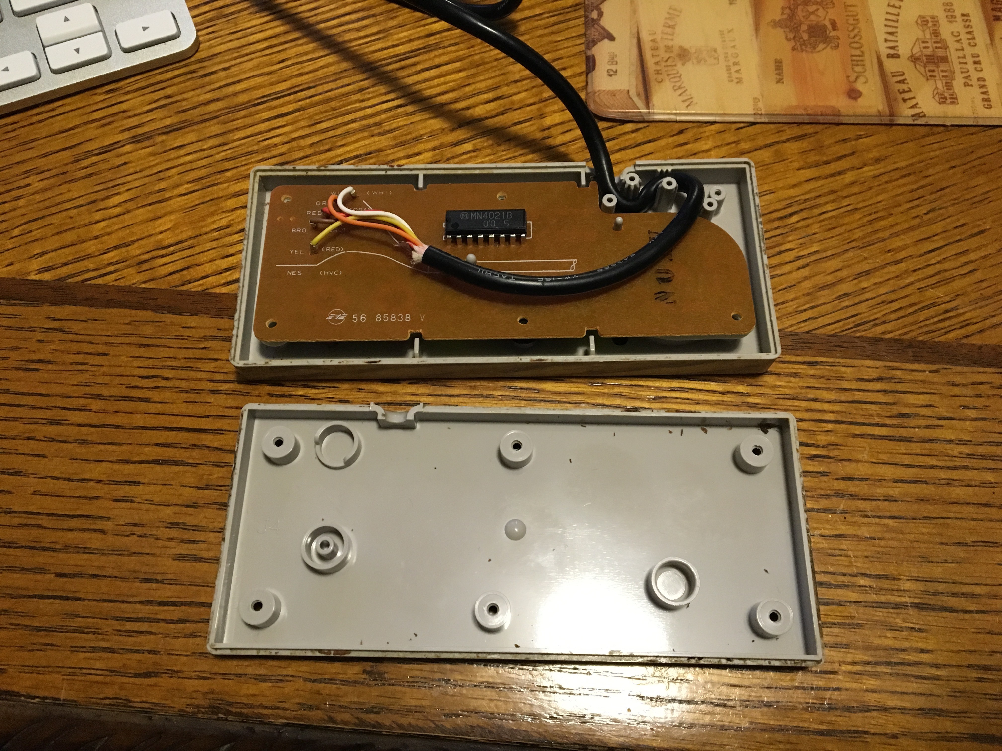
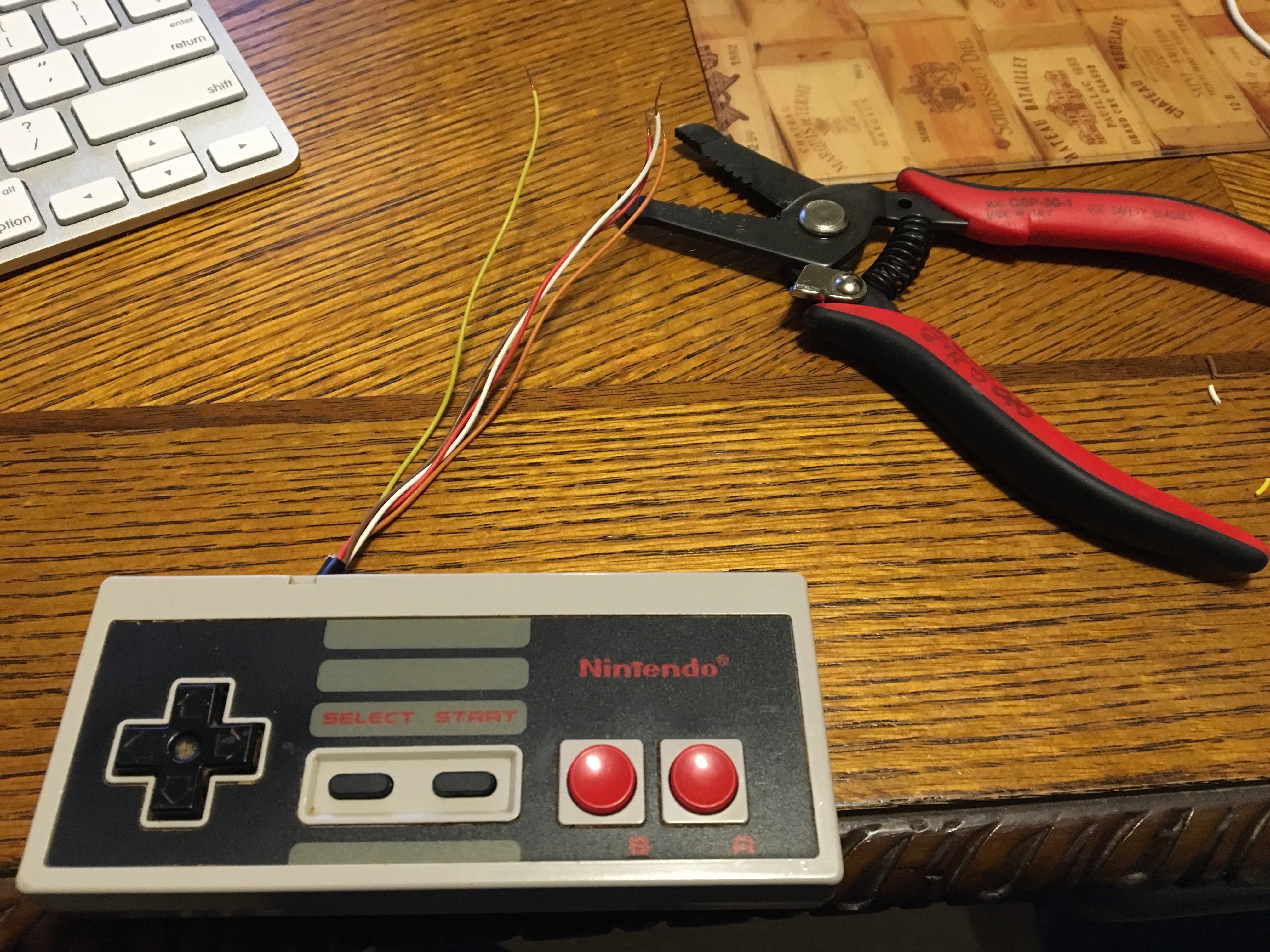
Disassemble the NES Controller and cut off the cord. I built out everything on a breadboard so I crimped some Dupont ends on to the wires. However, if you are a brave soul, you could skip straight to stripping and tinning the ends of the wires with a soldering iron and proceeding with the build out. I would really encourage a breadboard build if you can. The reason for this is that the instructions for the software driver state that everything will work fine with 3.3V power. However, my controller was unresponsive until I gave it 5V. See below link for reference:
https://github.com/RetroPie/RetroPie-Setup/wiki/GPIO-Modules#gamecon_gpio_rpi
![]()
![]()
![]()
![]()
-
2Step 2
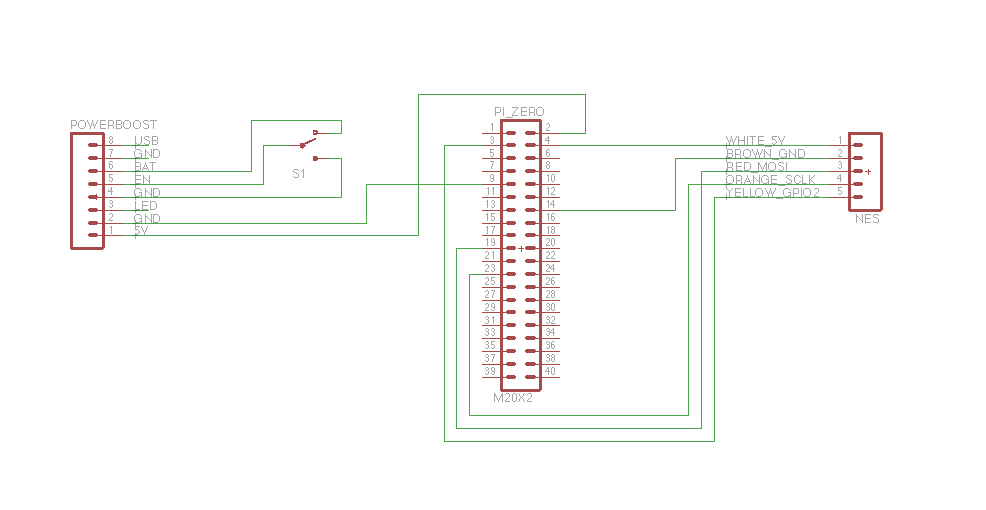
Breadboard all the connections according to the schematic attached to this project. I somehow lost my picture of the completed breadboard, so here's a picture of a half-completed breadboard. :-)
For the Pi connections, I loosely soldered breadboard wires to the GPIO pin holes with just a tiny bit of solder. Later on for final assembly I desoldered them by heating, gently pulling the pins out, and using a solder sucker to clear the holes.
For the boost charger, I did solder a pin header in and later cut the black plastic apart and desoldered the header pin-by-pin using the same method as above.
Be sure RetroPie boots and your controller inputs work. More on the configuration of RetroPie and RetroArch later in the instructions.
![]()
Yes this pictures shows a 2000 mAh battery. I really wanted it to fit... I had to downsize my dreams mid-project to fit the available space in the case.
![]()
-
3Step 3
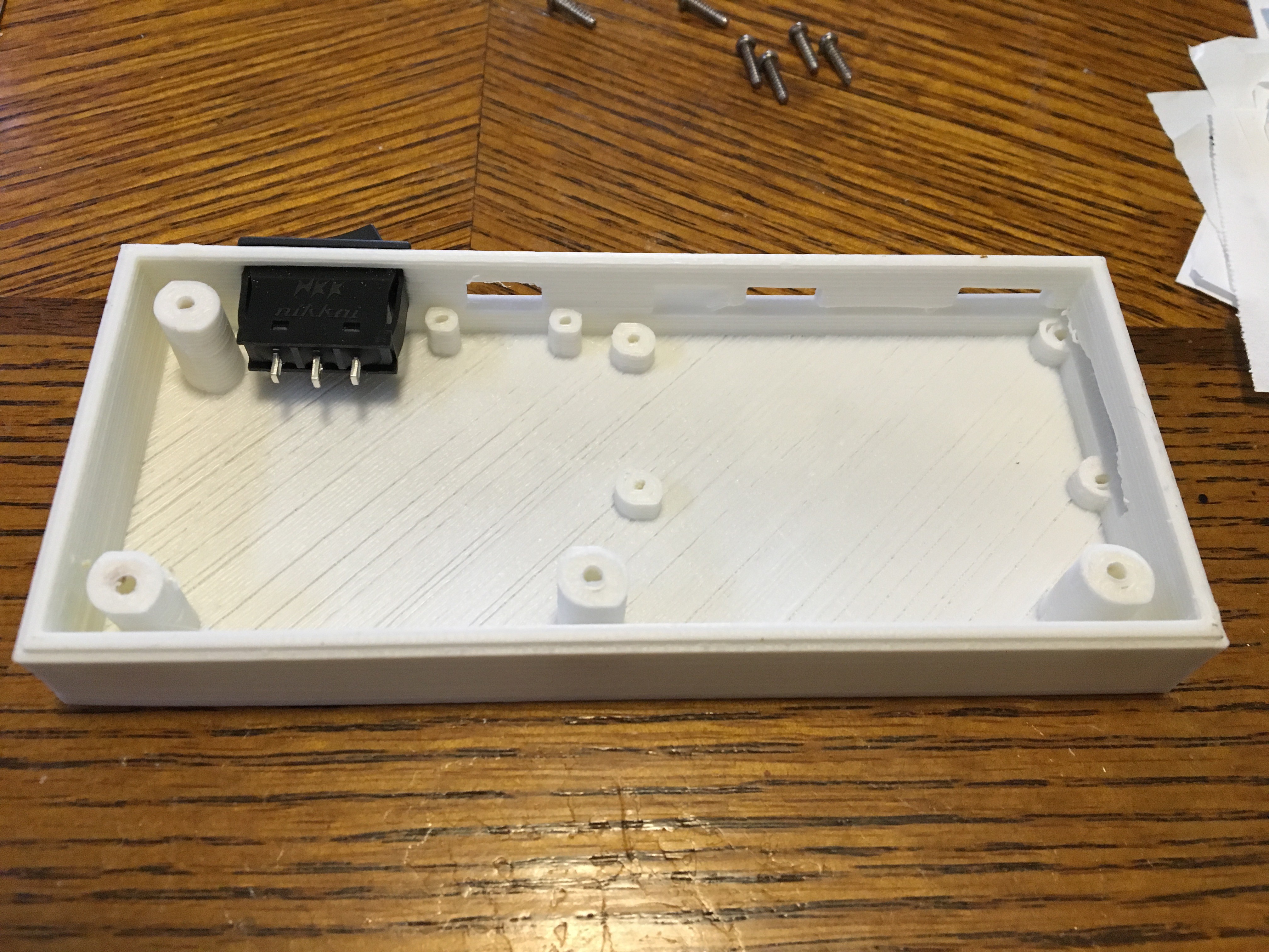
3D print the controller back with your 3D printer or your favorite printing service. Pop the switch in to the finished print.
![]()
-
4Step 4
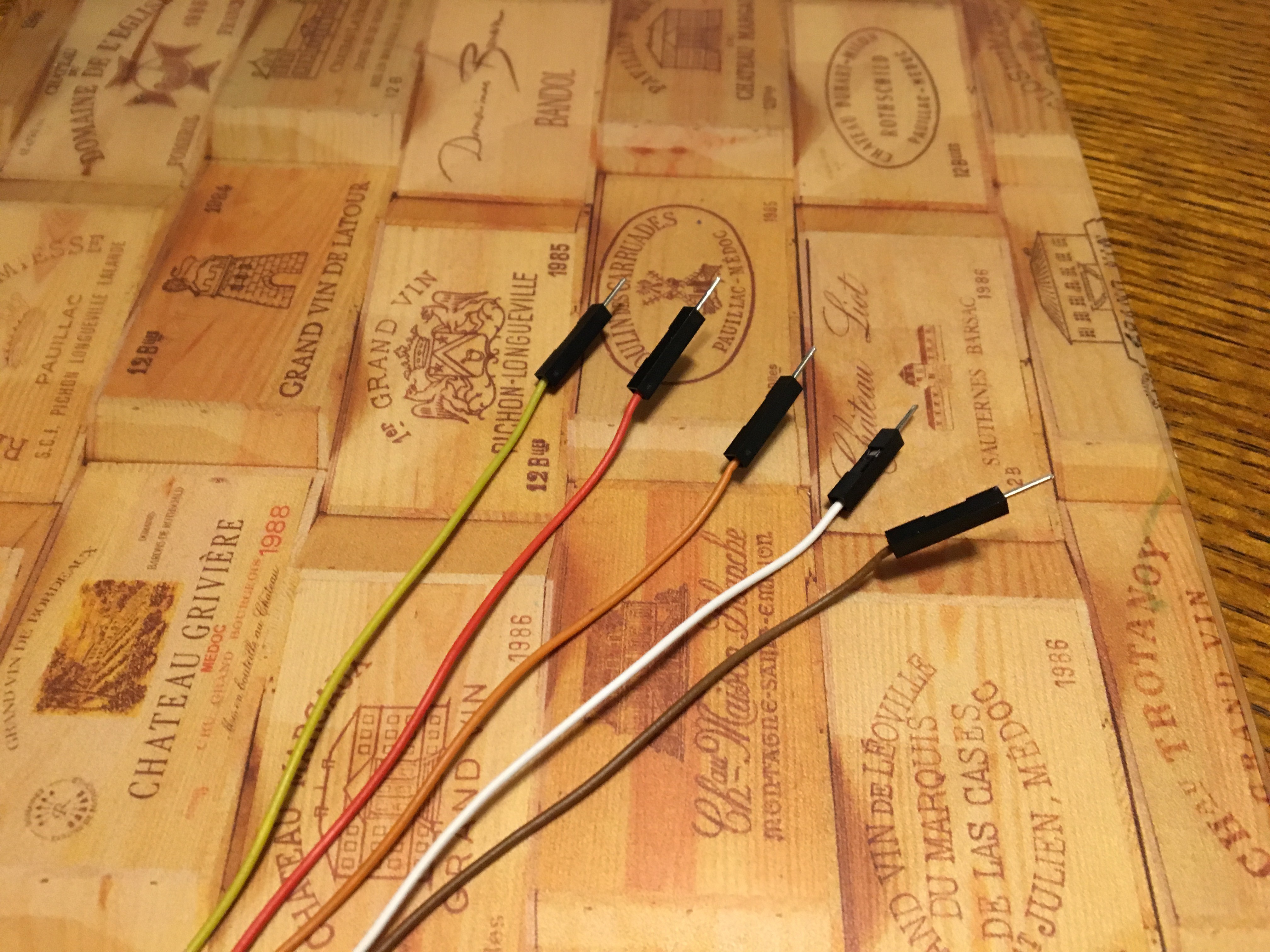
Cut your wires further if you need to and strip & tin the ends. Tinned wires go through holes a LOT easier than when they are not tinned. Braided wire can fray apart and cause electrical shorts if you aren't careful.
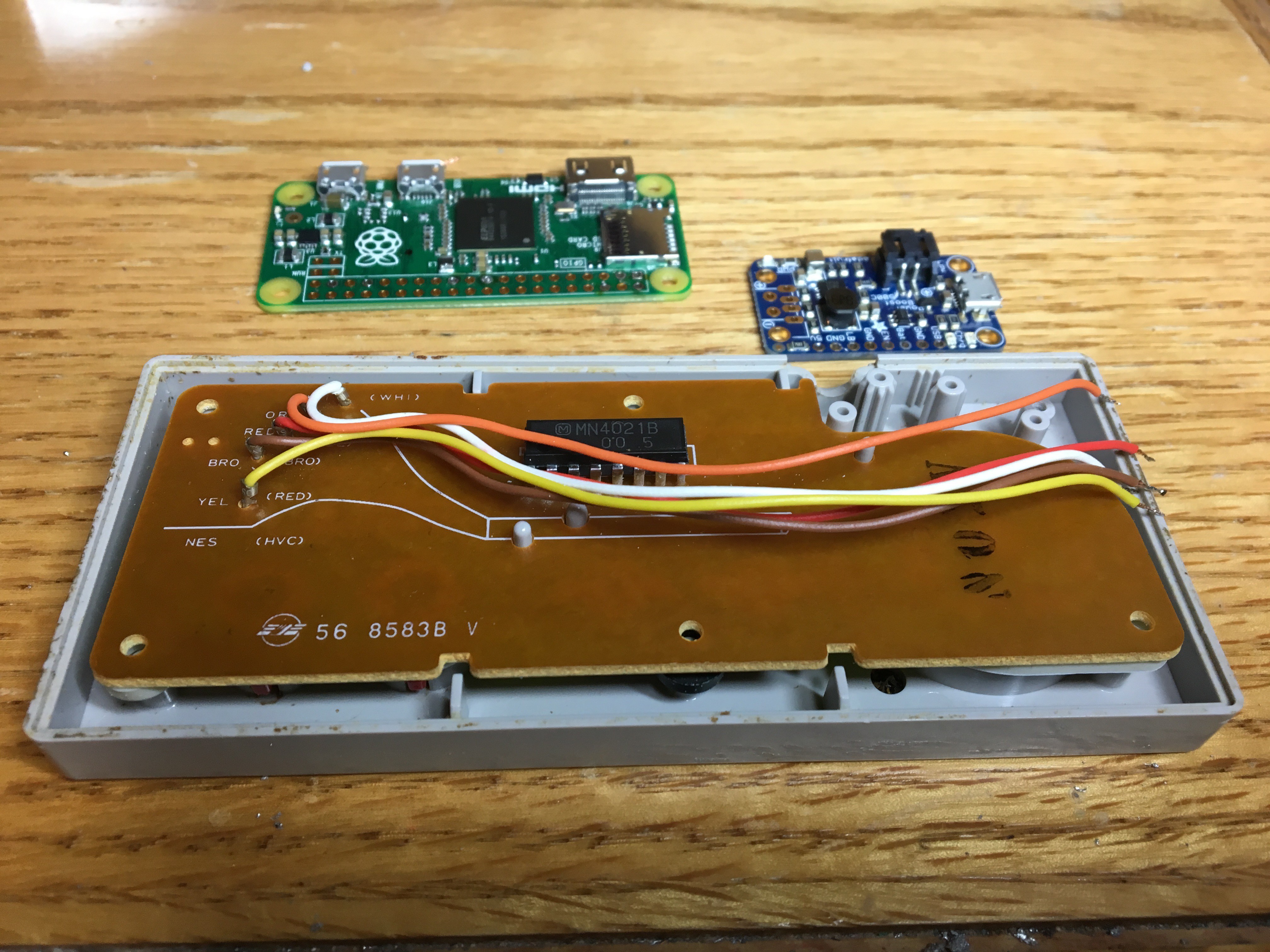
Gather the Pi Zero and the PowerBoost module. You'll need them for the next couple of soldering steps.
![]()
-
5Step 5
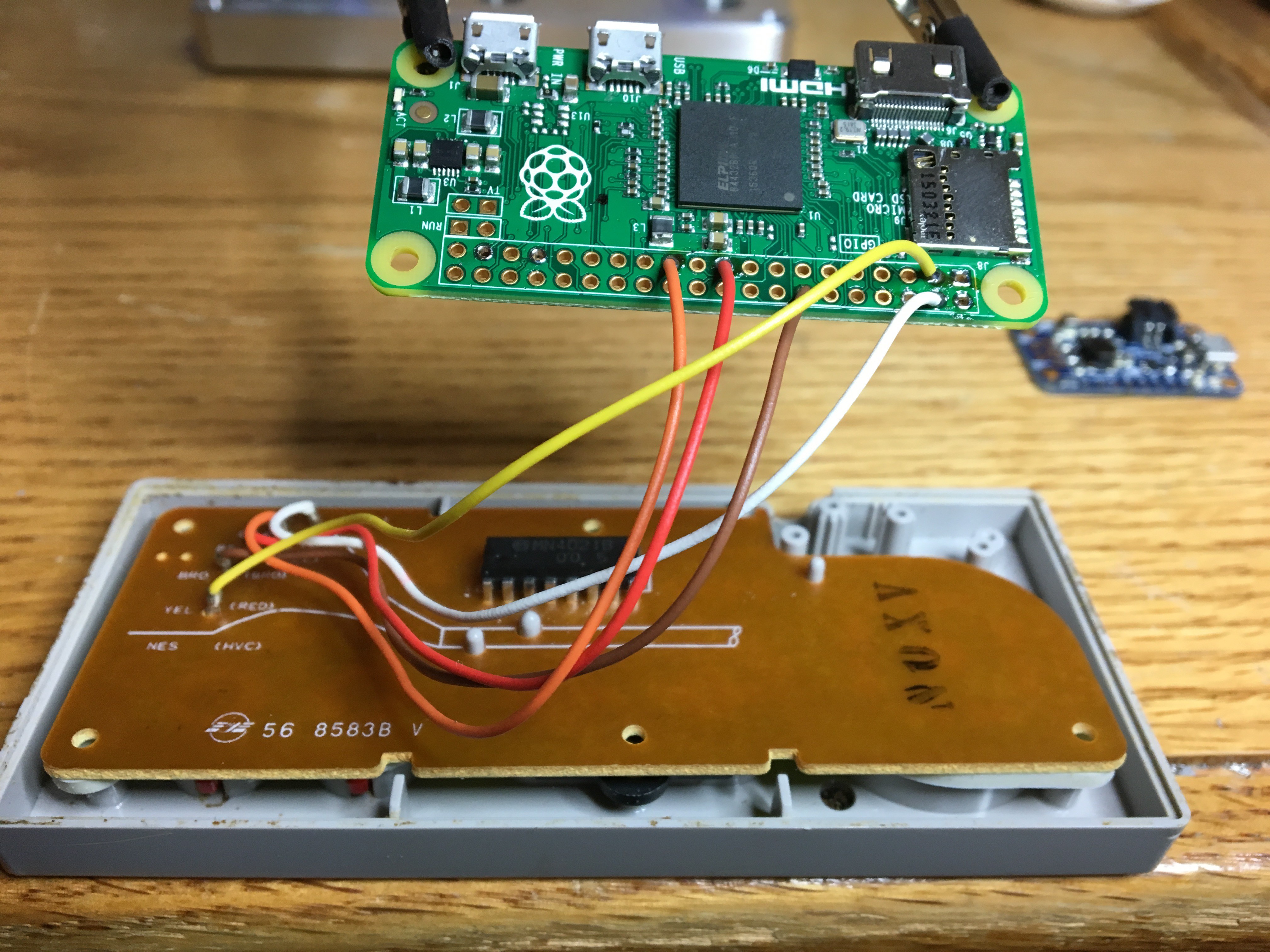
Solder the controller connections according to the schematic. A set of helping hands goes a long way here in avoiding frustration.
![]()
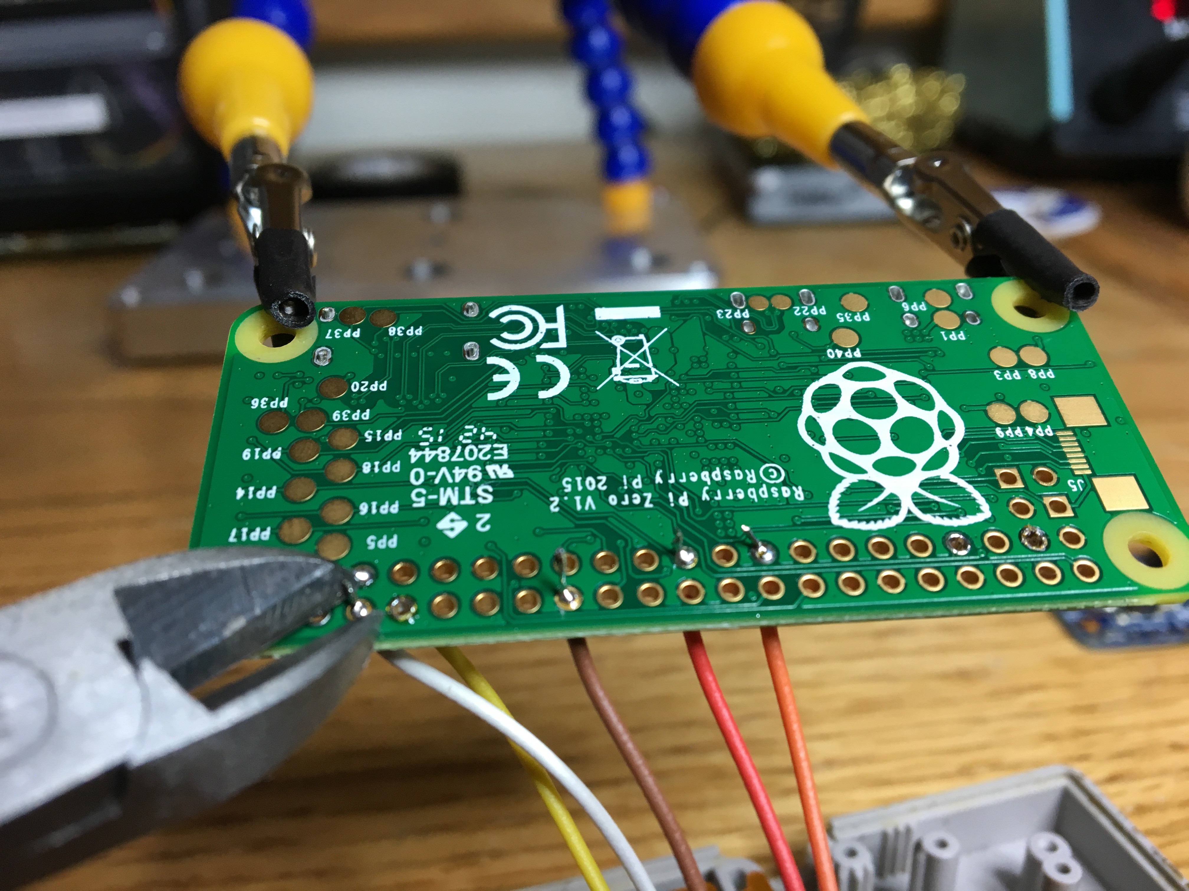
Turn the Pi Zero over and clip off any extra wire sticking through the back side with a pair of angle cutters.
![]()
-
6Step 6
Cut, strip, and tin some wire leads. It helps to put the components in the case to judge how much wire you need. Wire ribbon really helps to cut down on the amount of loose wires in your way when putting together the project. Use if if you have it.
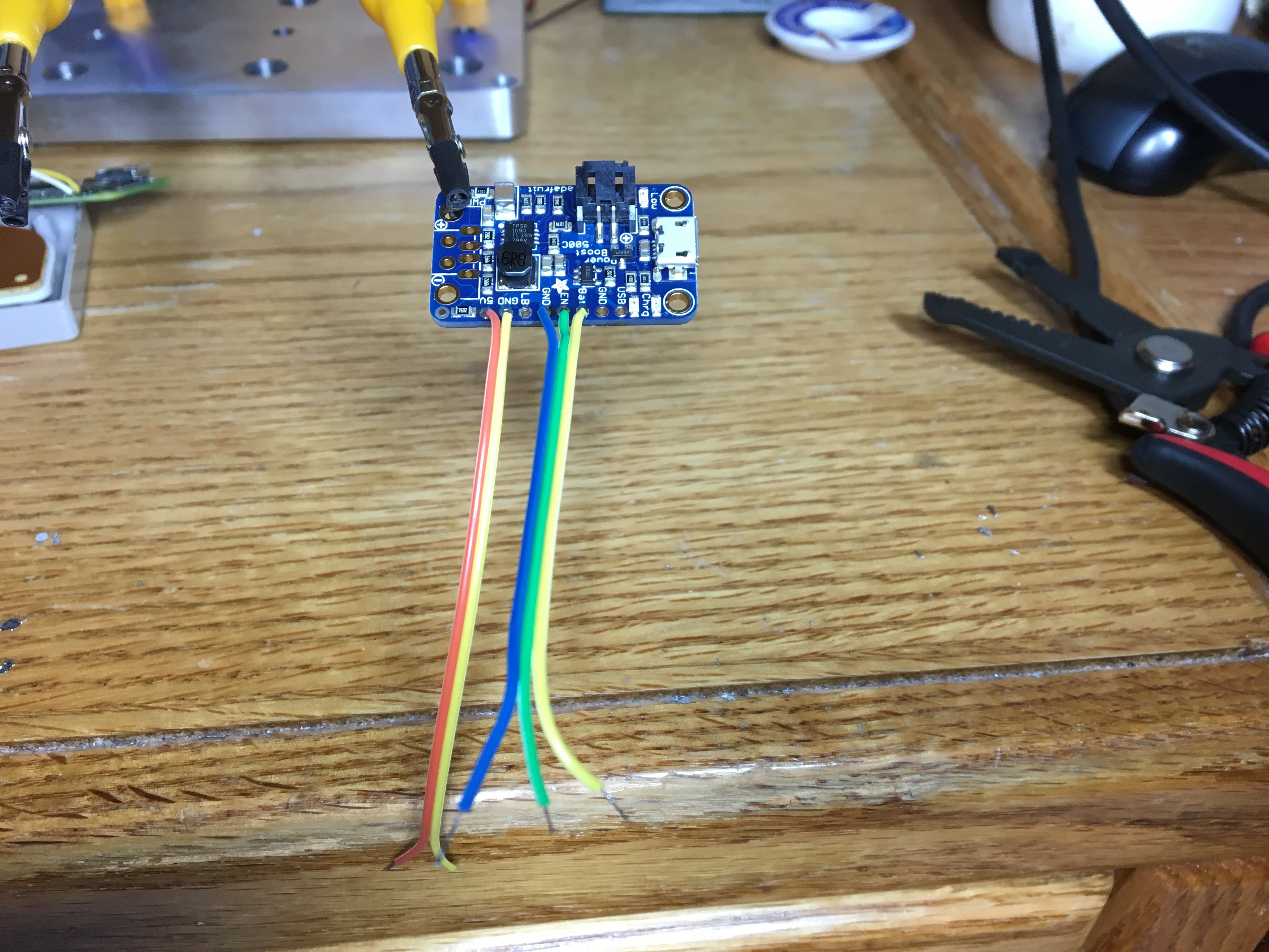
Solder the wire leads to the PowerBoost. Turn the PowerBoost over and clean up the back side with an angle cutters.
![]()
-
7Step 7
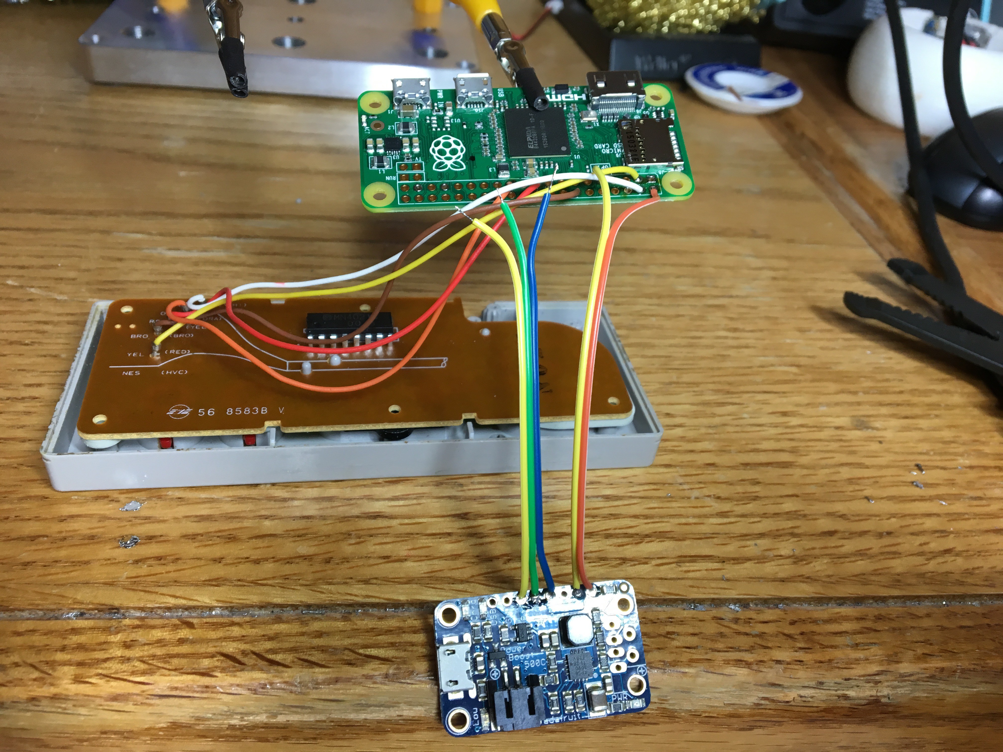
Solder the 5V and GND wires from the PowerBoost to 5V and GND connections on the Pi GPIO. Check the schematic for reference.
Clean up the back side of your new solder joints.
![]()
-
8Step 8
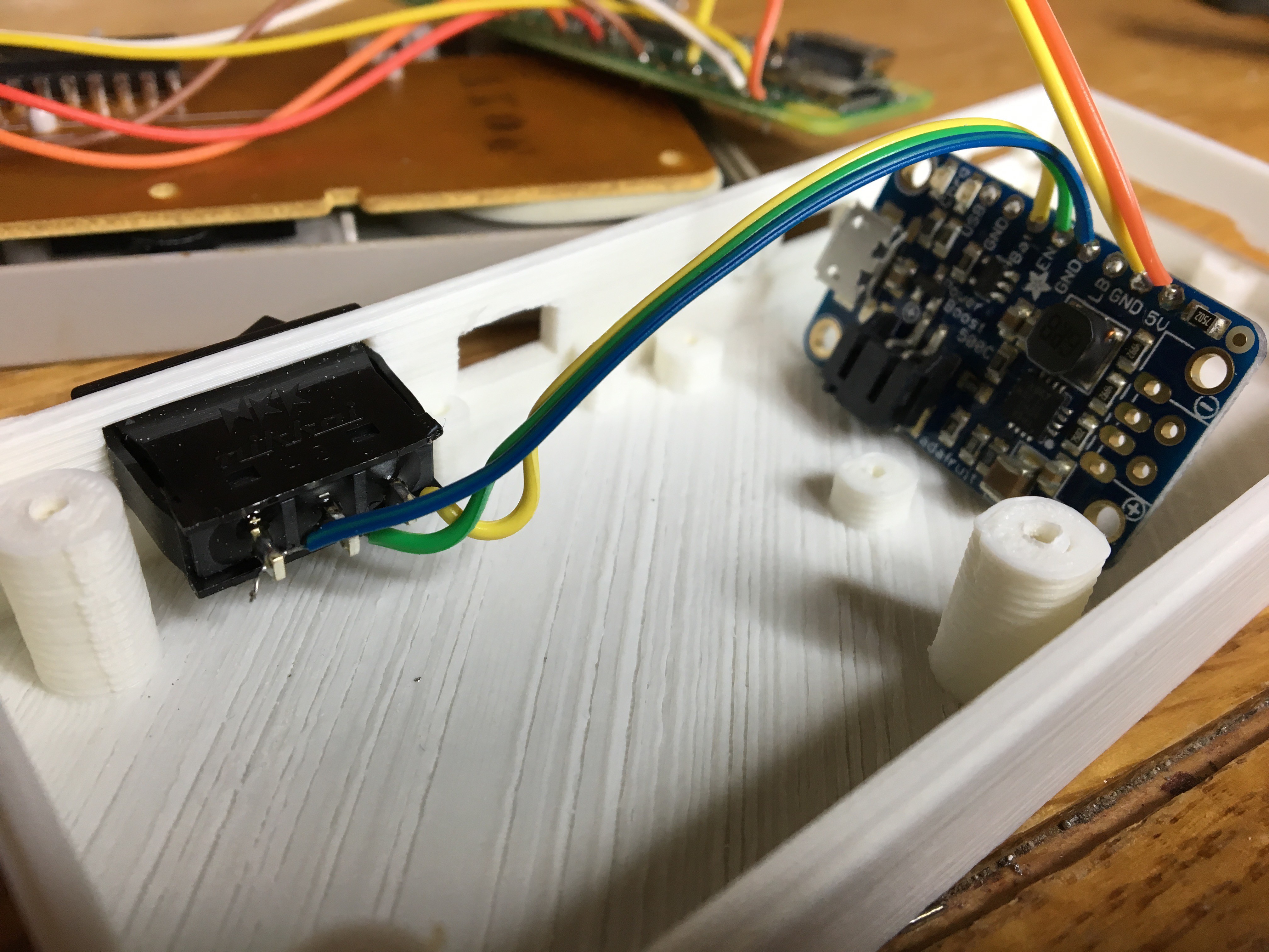
Solder the BAT, EN, and GND wires from the PowerBoost to the rocker switch. Check the schematic for wiring reference. Be sure to put the switch in the case BEFORE you solder the wires on.
![]()
-
9Step 9
Bonus Edit!
I was able to make this project work with an iPhone 5 or 5S battery replacement with some minor modifications to the battery itself and the 3D print. Using the iPhone battery gives you 3x the battery life as the 500 mAh LiPo. If you don't want to do this, skip this step.
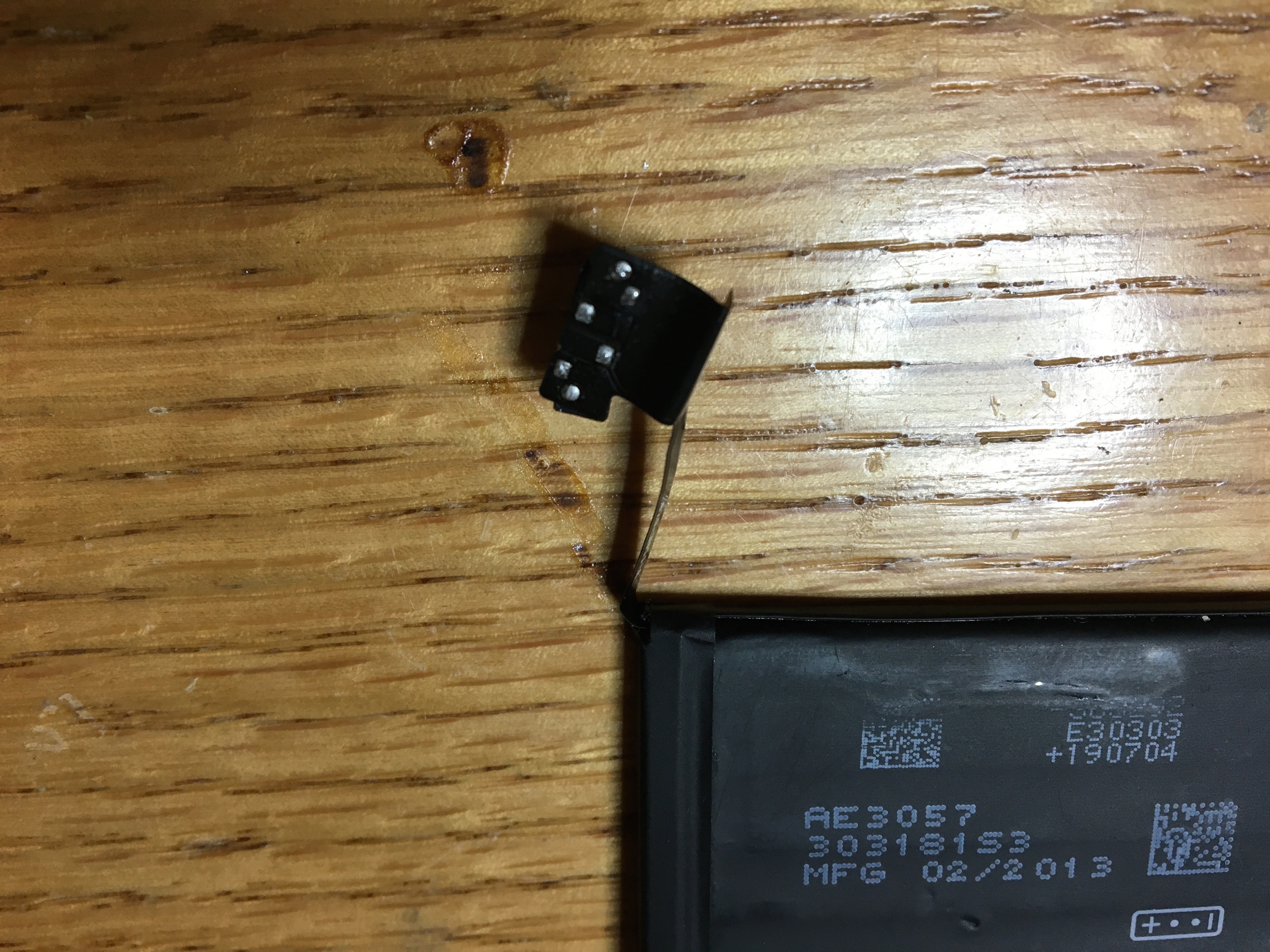
Start by using a heat gun to desolder the connectors on the battery. After that is done, you will be left with solder pads. It's very tempting to just remove the ribbon connector altogether and use the solder pads that the battery circuitry connects to. Don't do it though! You'll be left with a raw LiPo with no protection circuitry. This circuitry will protect the battery from over discharge, which damages the cells.
![]()
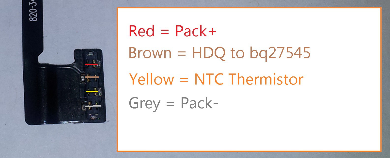
Identify which pads are + and -. See below graphic, courtesy of https://ripitapart.wordpress.com/2014/07/25/looking-inside-an-iphone-5-battery/
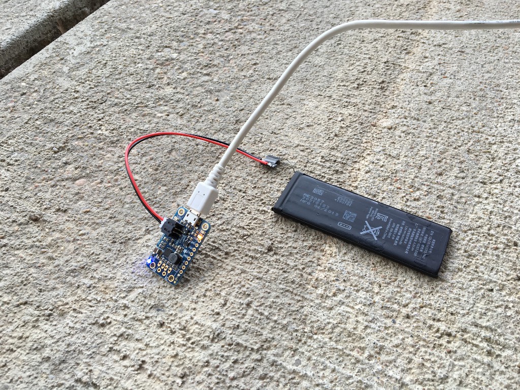
Use a multimeter to confirm that you get about 3.8V. It may register slightly lower than 3.8V because the battery shipped without a full charge.
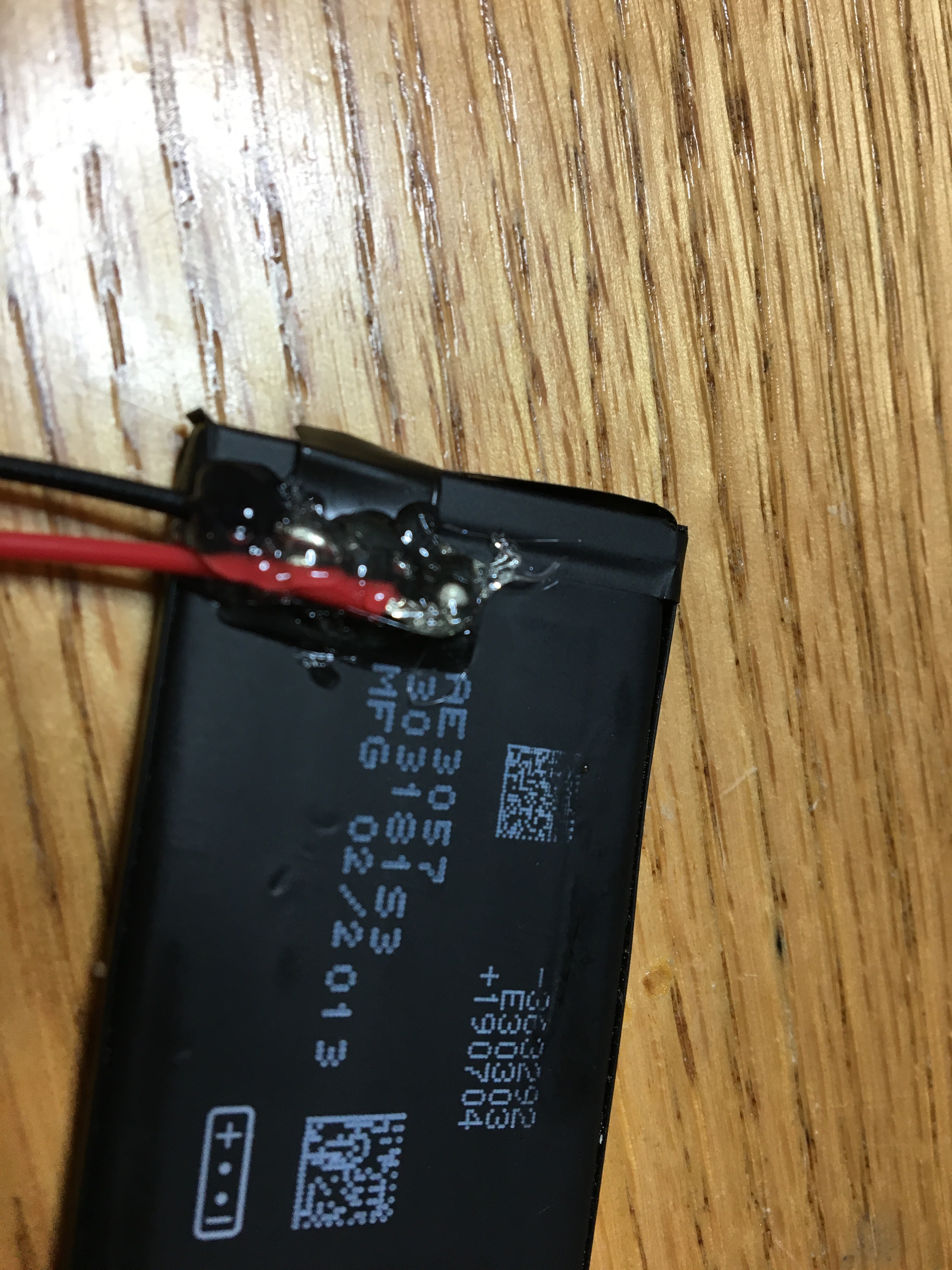
Solder the 2 wire JST connector, red to + and black to -. Be careful to avoid shorts. You are working in a small area with small solder pads. Give your wires a gentle tug to be sure they soldered to the pads.![]()
![]()
Again test your leads with a multimeter to ensure you have voltage. Fully charge the battery OUTSIDE and AWAY from flammables. Don't blame me if you charge your cheap Chinese knock off battery inside your house and it catches fire or explodes. Check in on it every once in a while to make sure it doesn't expand or get hot.
Once charged, hot glue the battery ribbon down to the battery and glue over all the exposed solder pads.![]()
Cover the battery hack with electrical tape over top from one side to another and then around.![]()
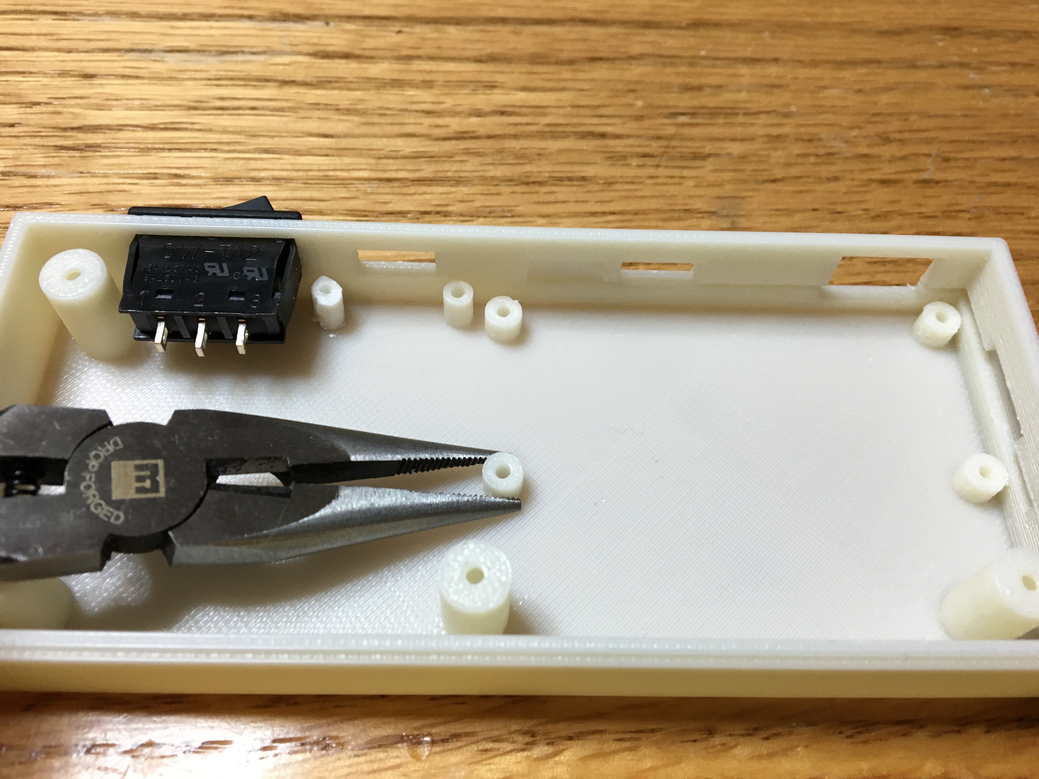
Modify your 3D print with a pair of pliers. Break off the lower left RasPi Zero mounting post. High-tech and complex, right? :-)![]()
![]() Hot glue the battery in place and use one less screw when mounting the RasPi Zero in the following steps.
Hot glue the battery in place and use one less screw when mounting the RasPi Zero in the following steps.![]()
-
10Step 10
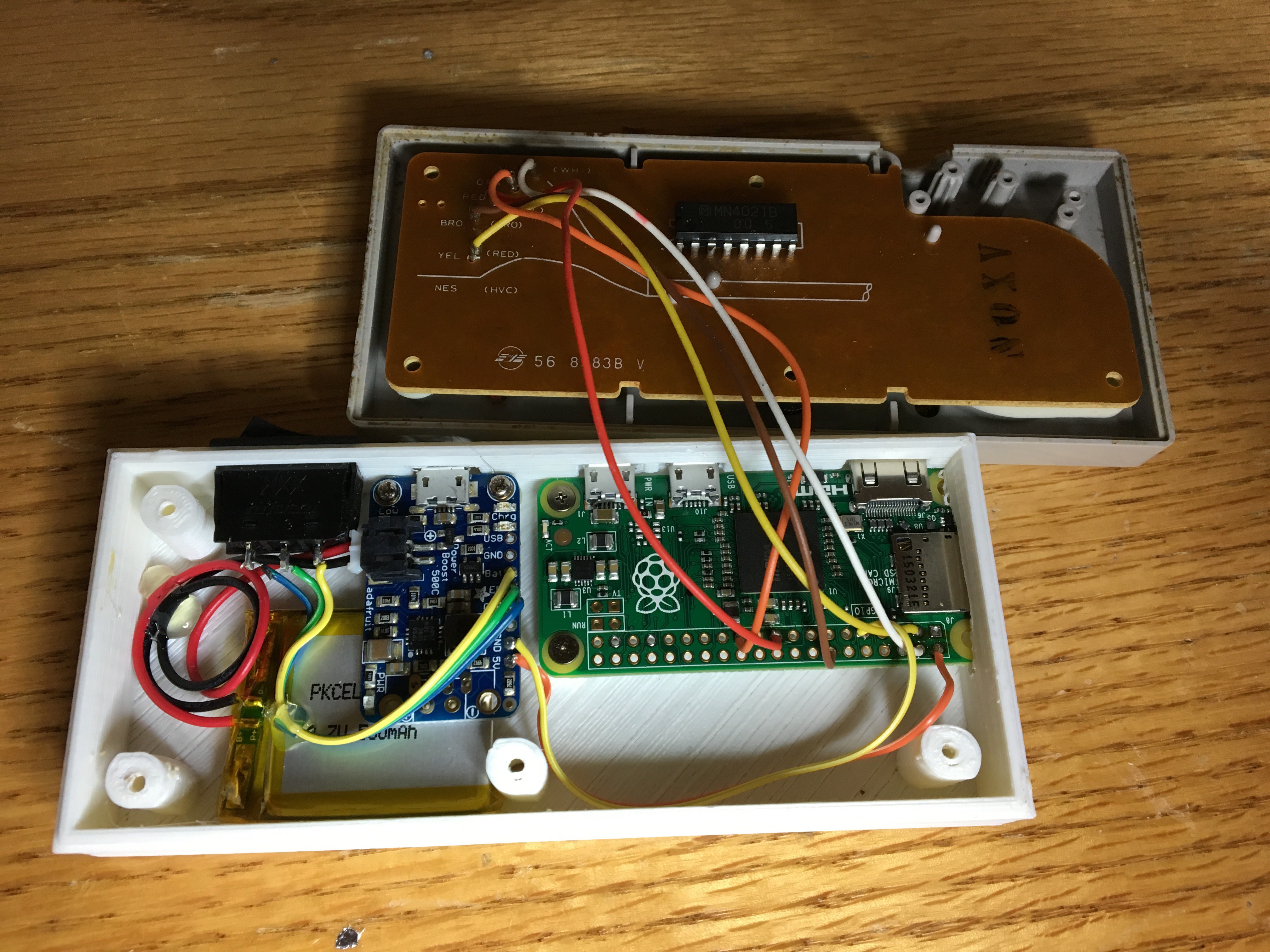
Slip the battery in place and tack it down with either hot glue or double-sided tape. Insert and screw down the PowerBoost and Pi Zero. Be careful with the length of screws you use and how much you tighten them. The screw down posts can be somewhat fragile. If you break one, mend it with superglue or hot glue.
Tidy up your wiring. I coiled and tacked down the extra lead length on the LiPo with hot glue. You want to ensure that the wires do not get in the way of the screw down posts when you are closing up the case.
![]()
NESPi Controller
Raspberry Pi Zero-based emulator in an NES controller case. Powered by LiPo battery and Adafruit Boost Charger.


 Hot glue the battery in place and use one less screw when mounting the RasPi Zero in the following steps.
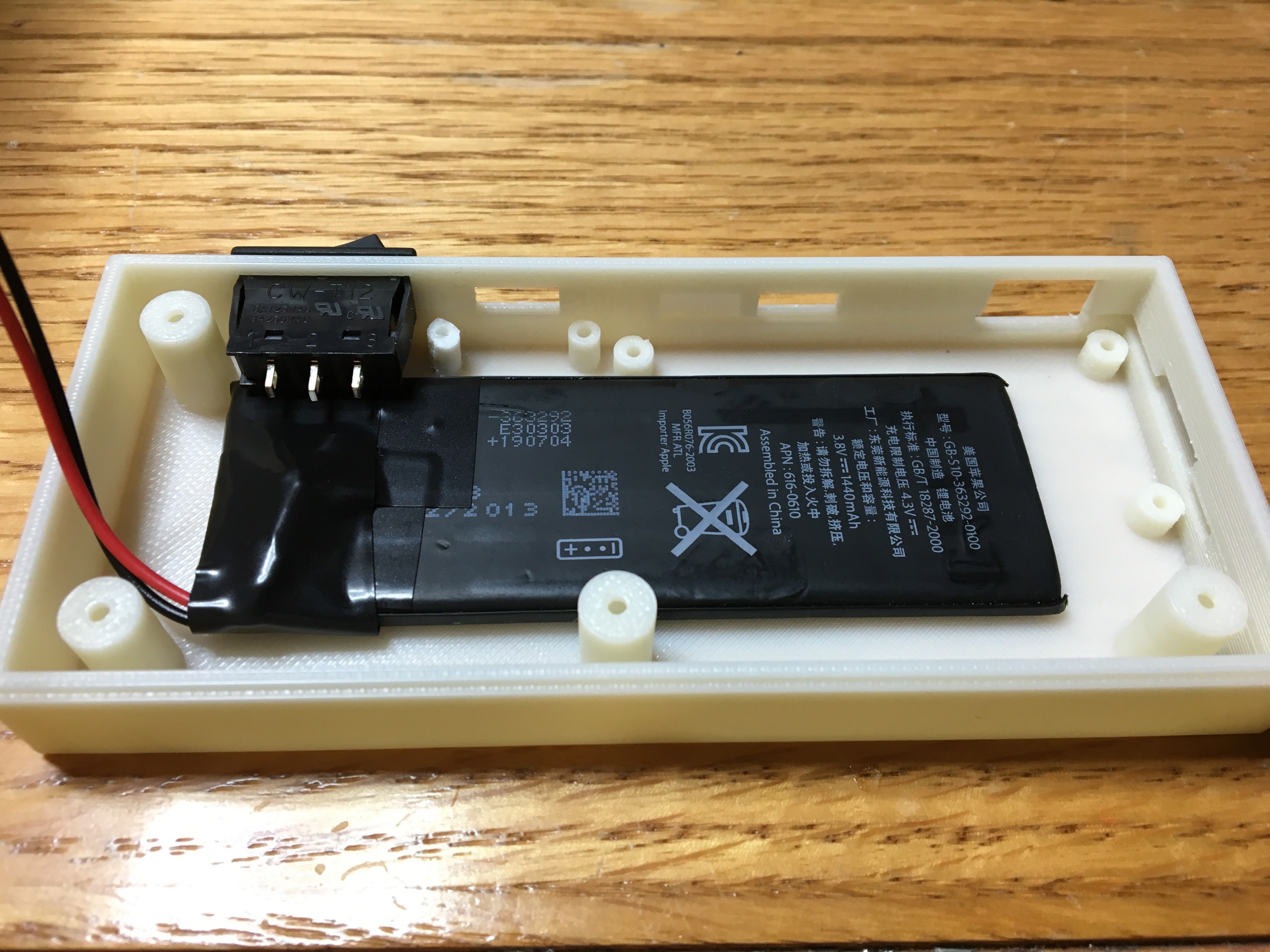
Discussions
Become a Hackaday.io Member
Create an account to leave a comment. Already have an account? Log In.