Close
0%
0%

Yet Another (PiZero) Wi-Fi 'Hat'

USB-less WiFi for the PiZero (and others)

Similar projects worth following
WiFi for the PiZero without losing your valuable USB port.

First let me need to acknowledge the amazing work done by @ajlitt with his project #RPi WiFi. This project is based on and inspired by this and this variation arose as the result of me destroying several ESP8266 modules trying to do his build.

Alas soldering the tiny memory pads proved too much for me. This gave me the idea to look for a solution with less fine soldering.

Enter Atmel's ATWILC1000, which comes in a friendly SD Card dev board version, which can be purchased from Digi-Key here. I then used a SD Card adapter to wire it up to my PiZero. Since it supports up to 70mb/s it seemed like a relatively good alternative to the ESP8266. Plus I've seen a large number of similar projects based off the ESP8266 pop up and thought it might be nice to try something a little different. This is my first foray into circuit design, for what it's worth.

wifi-hat.pdf

An early schematic of the WILC1000 based WiFi Hat.

Adobe Portable Document Format - 12.64 kB - 02/29/2016 at 17:41

Preview

  • An SDIO/MMC Hat?

    jarocks02/28/2016 at 22:14 0 comments

    I had some interesting ideas last week about a possible modular solution. With the abundance of SDIO cards available from sites like Aliexpress it would be nice to use these modules without any FCC testing (byo wifi). I ordered a couple cards from there earlier in the month but am not really holding my breath for them to come (guessing it'll be closer to the Summer months).

    With that in mind, I made a more elegant looking SDIO Hat and have it out on order from OSH Park, more on that when the boards come back, which should be sometime in the next couple weeks.

    I've updated my Github with the latest version of the WILC1000 based Hat and attached the updated schematic to this project page. Any feedback on errors is appreciated!

    Also, congrats to all the winners of the first round of the Pi-Zero contest!

  • Something smaller

    jarocks02/21/2016 at 20:02 0 comments

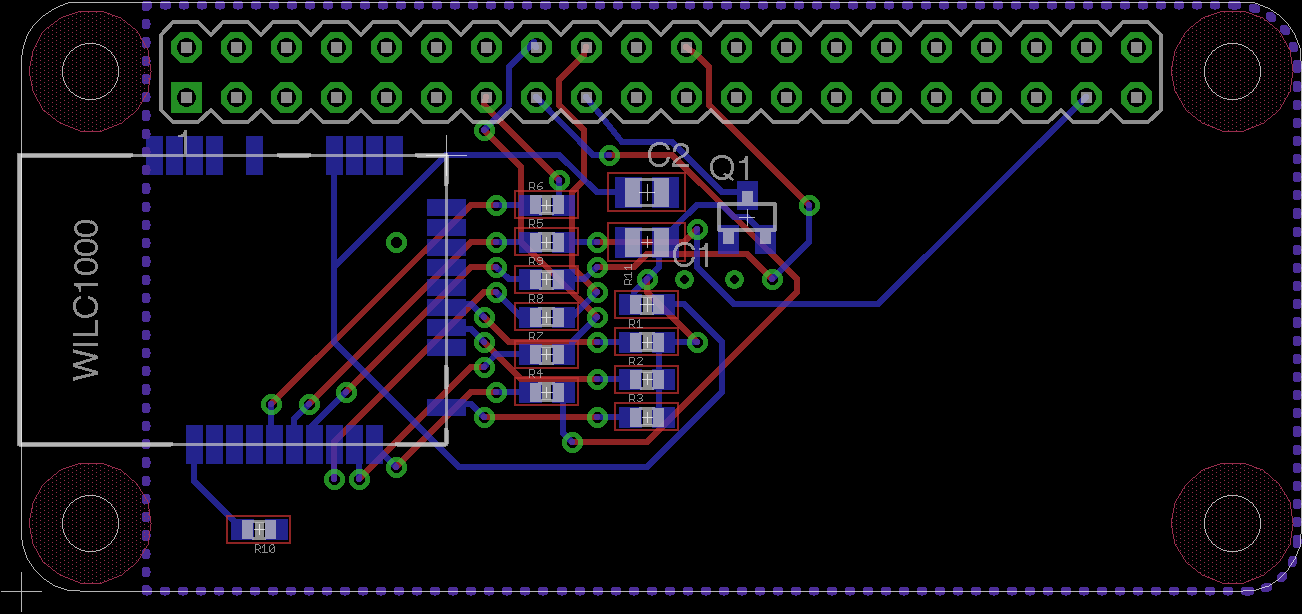
    So as you all have kindly pointed out, the large sd form factor dev board made by Atmel is less than ideal for use in a HAT which is supposed to help cut down on bulk. I completely understand this. I've come up with a rough schematic and board layout for a WILC1000 based WiFi hat.

    There are some major stability issues I am still trying to work out, in that the entire interface goes down after the throughput reaches a certain threshold (around 10Mb/s). I am pretty sure it's a power related issue, the chip probably needs more current than the 3v3 rail can provide. My Pi doesn't want to stay powered on when I try to measure current draw of the card which is an issue.

View all 2 project logs

  • 1
    Step 1

    Make sure your an SD Card breakout board which breaks out all 6 SDIO signals.

    Then wire the signals to the corresponding pins on your hat's gpio header, keeping the wire length as short as possible.

    SDIO SignalGPIO Pin #
    SD_CLK15
    SD_CMD16
    SD_DATA018
    SD_DATA122
    SD_DATA237
    SD_DATA313
    3v31 or 17
    GND6, 9, 14, 20, 25, 30, 34, or 39

    I also placed a 10uF 16V Cap across the GND and 3v3 rails close to the card itself.

    The card already includes 75 Ohm resistors on the data lines.

  • 2
    Step 2

    First make sure you have at least 1GB of free space on your MicroSD card (you may need to use raspi-config).

    Then prepare the Pi for kernel module compilation:

    # Update your RaPi
    sudo apt-get update && sudo apt-get -y upgrade
    
    # Install the Prerequisites for Module Compilation & Menuconfig
    sudo apt-get -y install bc rpi-update git libncurses5-dev
  • 3
    Step 3

    Modify the boot config, update firmware and kernel, and reboot:

    # Modify /boot/config.txt so the sdio dtoverlay is loaded on boot.
    sudo sed -i -e "/^dtoverlay.*sdio/d" /boot/config.txt
    sudo sh -c 'printf "dtoverlay=sdio,poll_once=off" >> /boot/config.txt'
    
    # Install the latest firmware and kernel
    sudo rpi-update 
    
    # reboot
    sudo reboot

View all 10 instructions

Enjoy this project?

Share

Discussions

Vincent wrote 02/22/2016 at 19:49 point

Regarding initial PCB brownouts - since there is plenty of space, what about feeding power to the hat with an on board meaty regulator, which then  powers zero?

  Are you sure? yes | no

ajlitt wrote 02/23/2016 at 16:16 point

The Zero's switcher should be good for at least an amp at 3.3V based on the Adafruit teardown.  But the Zero uses cheaper, lower profile inductors than the other Pis, so it may not handle such high currents.

Scoping the supply at the module would give a better idea of what's happening.

  Are you sure? yes | no

Michele Guerra wrote 02/21/2016 at 23:04 point

Beatiful and very small. Well done guy! Where can I find the insulated copper wires you used to make small connections between pads? 

  Are you sure? yes | no

jarocks wrote 02/22/2016 at 06:43 point

I salvaged it out of an old PC fan. 

  Are you sure? yes | no

Martin wrote 02/22/2016 at 10:02 point

That's normal "magnet wire" or enameled copper wire.

  Are you sure? yes | no

helge wrote 02/21/2016 at 14:21 point

would it be possible to create a microSD variant?

  Are you sure? yes | no

ajlitt wrote 02/21/2016 at 05:36 point

If you need to thank anyone, it should really be pboettch at the raspberrypi.org forums for asking all the right questions about the Pi's SDIO and getting the bus working with a different SDIO device.

  Are you sure? yes | no

deʃhipu wrote 02/20/2016 at 21:47 point

It looks a little bigger than I expected...

  Are you sure? yes | no

jarocks wrote 02/21/2016 at 02:06 point

It's still very much a work in progress.

  Are you sure? yes | no

Similar Projects

Does this project spark your interest?

Become a member to follow this project and never miss any updates