Andrew Bills
-
Making the Controller dance
03/26/2016 at 10:03 • 3 commentsSo, I'm getting a bit concerned about having this together in time for a con that is in 2 weeks time (by bit I mean VERY) I was relying on someone else for the shell that I need around the frame and they have so far let me down. It is looking pretty doubtful to get it done in the short term and if it is done it might only do the most basic remote control features.
Speaking of the remote control, I made some effort to try and polish that off yesterday/today but can only get so far due to the fact that the induction charger I need was faulty and I've expressed it off to get a replacement. Soon as that arrives I can solder it back in, connect the plunger switch (which I had 3D printed and the files are here) & glue it down.
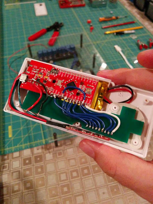
The controller is very tight (as expected) so there is a little jiggery pokery to get all the cables in the shell, but it is doable. I will need to add some foam packers when the switch and charger are in too to make sure stuff doesn't move about.![]()
You will have to forgive my horrible soldering ability. I had originally intended to use headers on the wires but the space was too small so I had to remove it (poorly) and go direct. The button pad board is per the Gerber that is also in this project that I got made as a prototype (min order of 5, so I have spares). One pin is for grounding and the rest are for input. I had some problems with the FIO v3 that one of the digital pins (14) was actually a different number (17) and try as I could I couldn't get anything out of pin 11 hence the one cable that just jumps over to pin 4.
Fun thing if you do this, it does vary from the schematic I put up originally for the controller.... I have the 8 buttons on digital pins 4-10 + 17 all of which are initialised as HIGH to use the onboard resistor so I don't get button bounce during digitalRead (can happen). My custom part 9th pin I couldnt get right with the onboard pins (maybe due to the faulty pin I was trying to do everything with until I figured that out) so its just connected to ground given the other pins are all set HIGH.
Code wise the thing outputs to Serial1 (xbee socket) and just pumps out a string of current values of the controller on a 50ms loop. I did slow that down at one point but felt it a bit sluggish when coupled with the logic.
Long story short for the code it outputs:
RFID Tag (inserted inside the case), 8 button settings of on or off, xyz for accelerometer, xyz for the gyroscope and xyz for the magnetometer. It also outputs the pitch, yaw and roll per the Madgwick filter but ill come back to that. All comma separated.So I elected not to made corrections to the calibration of the 9DOF sensor stick I am using because I read bad calibration can be worse then ok factor calibration. However the Accelerometer part has a self diagnostic I could call on at start-up so I did that. The magnetometer & gyro didn't really have the same options and really depended on more offsets being used to set them up.
What I have included though is on top of the standard calibration to use the Madgwick filtering for AHRS on the 9DOF in the controller. Considering I may want to use the controller as a short term follow me treating it like a drone IMU seemed like a good idea (even if I don't get to use it right now). Basically it takes the accel, gyro and magno data and constructs it into the pitch, yaw and roll mentioned earlier. But the added bonus is when it does that it will do some sampling filtering to help with gyro drift (because all gyro's drift, its what they do apparently as they warm up... supposedly they will settle down but yeah).
Anyway as soon as I get the induction charger replacement Ill connect that up, solder in the external switch & I will be good to close up the controller. Earlier versions of the Arduino Fio allowed for remote bootloading with a little soldering but I am led to believe that isn't an option on the version I have so I wasn't game to further butcher the board with terrible soldering.
Couple of screws and a little foam packing and it will be closed up not to be opened again.... but definitely some lessons learnt if I make another controller as to how to save a bit more space.
As it is Zombie Jesus weekend (Easter) and I wont get those components tomorrow I can go back to trying to get the RPi3 working the way it needs to out of the box. The RPi3 which is a better choice for performance unfortunately doesnt have the serial working the same way as a RPi2 due to the inclusion of BTE. Ive followed a few guides with no success so Im going to start over again with the most basic one I have access to and hopefully I can move past solving problems I shouldn't have to.... (else Ill have to revert back to the RPi2).
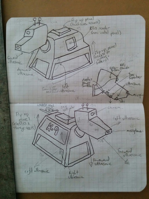
For anyone's amusement Im also including the prop diagram that most people work to. I was trying to find someone with CAD (and the ability to use it) to convert it into some slices I could get CNC'd into some impact foam panels I found but no luck yet.
-
Finally starting...
03/13/2016 at 11:05 • 0 commentsI received the motherboard spacer/mounts that I wanted to use for the project finally on Friday, which meant on Saturday I had to track down screws to fit seeing how these eBay special ones had inconsistent thread depths (which were too short for my 10mm screws). Fortunately I was able to get some from a RC Hobby store. While they are all hex that isn't a bad thing.
![]()
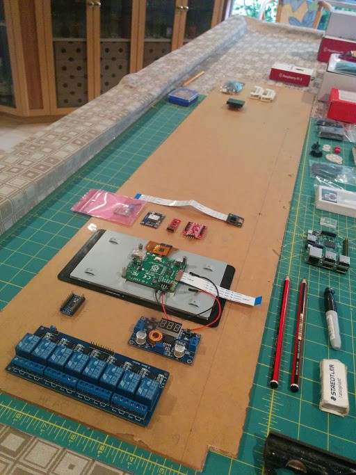
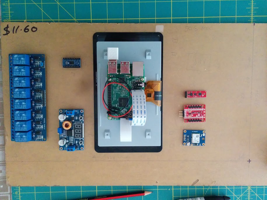
Today I cut the majority of the perspex & drilled holes for mounts for all the components I have for the main 'sandwich'. There are a couple of components that do not have screw holes or have components too close to their holes for me to screw down so not everything in the picture is 'attached', but even for the items that I didnt screw down entirely I still used the mounts for clearance and support. The items that didnt have screw holes I made a couple of holes to loosely zip tie the part down, which will stop it moving when the cables are also attached.
The standard mounts are only 10mm but the longer ones are 50mm. I put a hole in one piece so the touchscreen could be accessible from the top, but the bottom piece is there only for 'protecting' the wires from accidentally being pulled/touched/etc.
![]()
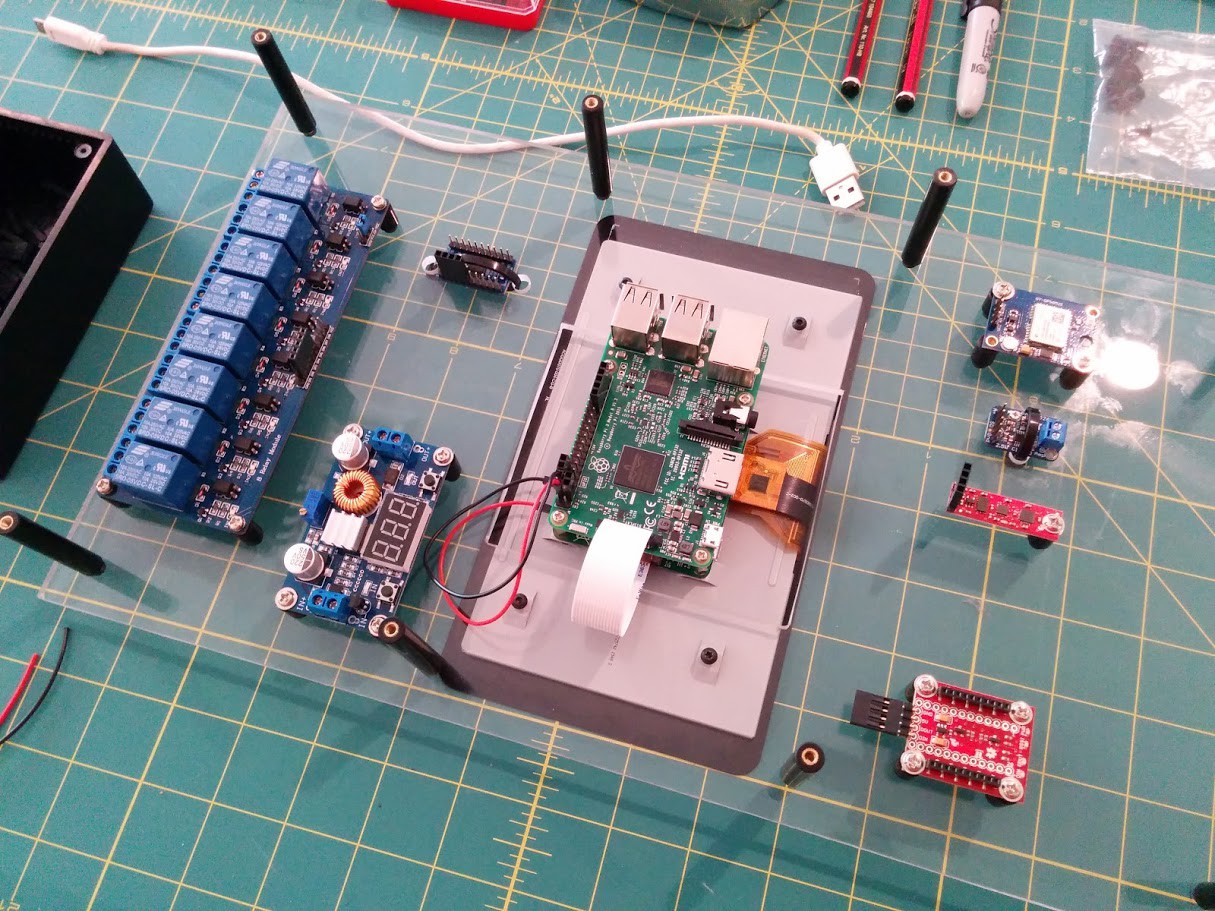
For the purposes of initially hooking everything up I've connected the relay to the 5v on the RPi instead of the battery, for now. This is just to let me check each part as I hook it up, so far I only had time to hook up the 8 channel relay (only 5 channels to be used) and the 9DOF (which I will need to programmatically cater for if I have mounted upside down, hopefully OK).Hooking this up with the USB for power lets me configure & update the Pi which I have switched with a RPi3. The upgrade means more power, more heat and a need to disable the inbuilt BTE because I need a serial interface to the XBEE. It also means inbuilt wifi though which is a bonus over a dongle.
![]()
I only have a USB breakout to attach which I will use to power the RPi through it's USB port instead of the GPIO as I learnt there is a mah limit through the pins. As soon as that arrives I will drill some mount holes to attach and hopefully have some more time to do some more hookup wiring.
I have decided on some 16Ah 22v Lipo batteries. I had also purchased some 'explosion' resistant metal protective containers for them after getting advice from the retailer they would fit. Unfortunately I discovered that while they did barely fit they also did slice open the battery leads. Lucky that it only cut one of the battery terminals & that the battery wasn't fully charged as I expect that would of done some serious damage to someone (with the 2 batteries in parallel I assume 32Ah @ 22.2v).
I've sent back the battery holders for a refund, but I also sent back the battery for a RMA & replacement seeing how it cant be safely used now + I did purchase the holders on their advice that it would be fine. Didn't really need the added cost & aggravation but hopefully that wont be a problem (even though it did add cost to courier back)
-
Bringing you up to speed.... part 2 (with some pictures this time)
03/05/2016 at 02:21 • 2 commentsSorry didnt realise I couldnt edit the project log but just a couple of images to help with the previous log...
As an overview the basic concept will be like this. Ultrasonics for forward, left and right. With an additional ultrasonic being down facing in the head so K9 doesn't get driven or drive down stairs.Also in the head will be the RPi camera mounted in the eye port with the microphone in the nose & 3W speaker also in the head. While the voice recognition may not be available to start with it's easier to just wire it up now. I am also going to have a master power switch under the head which should be hidden enough but accessible in case of emergency.
On one side the RFID will be mounted behind the panel builders often use for a TV (I thought it a waste of power) with the bottom half of the panel being able to be lifted up for access to motors/batteries. The opposite side will have the top half of the panel being able to be lifted up for access to the induction charger + internal storage shelf.
The electronics will be mounted on a piece of perspex under the top with the panel on top being flip up to access the touchscreen for basic functions. I will put a second piece of perspex under the layer with the electrics mounted to protect the wires from being touched/pulled accidentally. So sandwich style with a 50mm motherboard mount spacer holding them together.
![]()
The perspex I have marked out but as I havent recieved the mounts yet there isnt much rush to cut yet. There will be the 2 perspex of the larger size as mentioned for sandwiching the electrics but I also have 2 more smaller pieces for side mounting of the RFID reader & another for the 24v relay, 24v power rails & the motor controller for down lower. I want to mount those parts vertically so I can see the wiring if I need to get to it.
Most of the power stuff is together with the XBEE & GPS specifically being closer to the tail where the high gain antenna will be (I have a multiband antenna on it's way also that should do the 1500 range for GPS & 2400 (2.4) range for XBEE. The Amp & the 9DOF are also mounted here with the 9DOF being as central as possible.
The RPi & Touchscreen is shown upside down here as it will be face up for access from under the top panel. Also the USB plugs are accessible from the storage panel side so I can remove the WIFI dongle, add a keyboard or even a storage key if I want to do some timelapse. The rest of the parts will be mounted 'upside down' as shown. I will be adding a couple of holes to run zip ties through for the purpose of cable guides/management (you might see the small squares in pencil). The Logic convertor will need some ties to keep it in place as it has no mounting holes.
Missing from the below is the amp but that will be towards the top at the back.
![]()
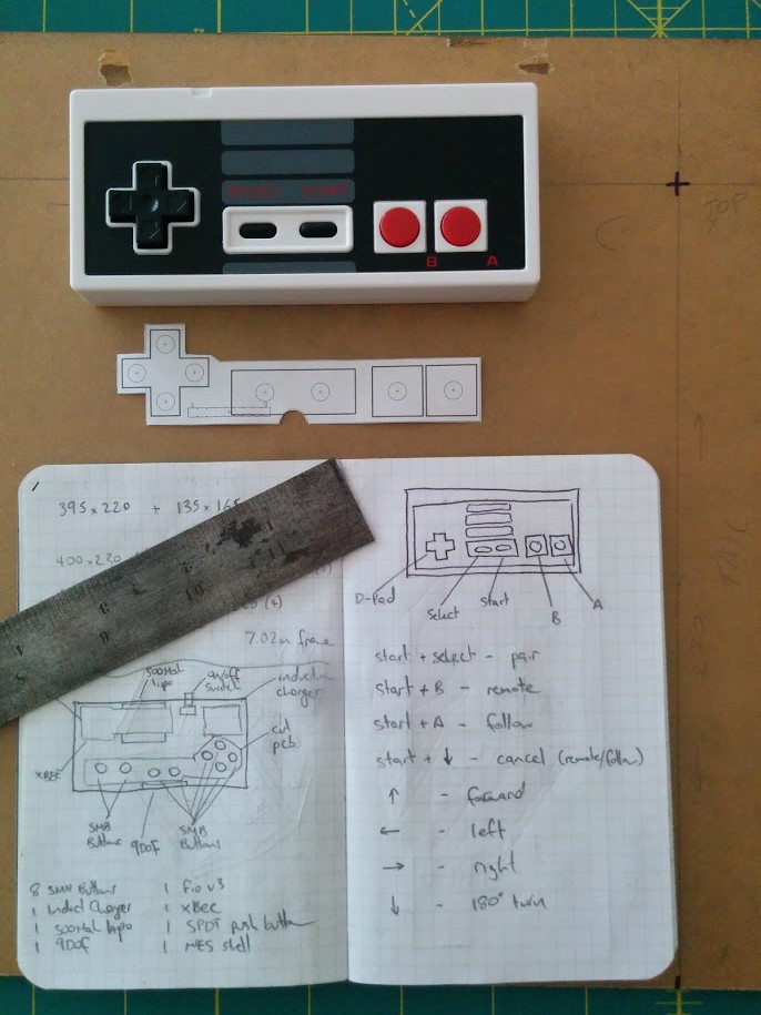
Lastly is the controller which will have a layout like the below. I have modified the shell I have to remove some of the mounts that reduce the amount of space & also removed the onboard jst/lipo connector to replace it with one on a short lead. I did that because the lipo connector height was too big without making a custom back for the NES (which I might do in future, originally I wanted a GPS in this unit too but that wasnt going to happen with the current space).
You can see from the below the controller with the layout of the PCB that ill get to put under the existing button pads and then wire to the Arduino (that will be fun to get the wires the right length & all to fit in the space). Current thoughts are the controller commands will be fairly basic with them just being broadcast then the 'paired' droid acting on them. That should mean I wont need to open this up again. I know you can wire up a XBEE to allow for wireless bootloading but with the amount of time it takes for parts to get to me Im not so keen on that if there is a problem.
Also missing from this is the RFID id tag which is going to be the glass one stuck to one side of the controller. The read range of the ID20 is about 2-4cm (I tried putting stuff in the way and the range was pretty consistant) so it should be able to read through the side panel in K9 providing I mount the reader flush as possible.
![]()
Ok that's it for today. Soon as the mounts arrive for the components I can start cutting perspex & mounting then start really playing.
-
Bringing you up to speed....
03/05/2016 at 01:48 • 0 commentsI should probably start using this log, so to catch up...
All the components are pretty much either in hand or on order waiting for delivery. There are a couple of parts like motherboard mounts that I'm going to use to mount parts to the perspex that most of the electronics will be on. Once I do that Ill be able to hook up most of the parts & start messing with code.
Power
I decided on the 2x 16Ah batteries from HobbyKing yesterday. They were marked down so there is some savings there but I needed cables for the hookups and a charger so the power still ended up being just about the most expensive part so far.
I am also a little paranoid about the batteries overheating/catching fire/go boom so I splurged on some save charging containers which only add 500g each. Hopefully I will just keep the batteries in those holders and I can remove them from K9 as a unit when I need to charge.
Ive also gone with 2 in parallel because it should definitely be enough for one day of heavy use but also means I have the option of changing over batteries on the fly (but will likely just go both for now til I know what consumption is like).
Controller
I am just waiting on a on/off push button switch for the controller before I can hook that together but I have decided instead of using the smb switches on hand cut board + soldering Im going to look at getting a custom pcb made. Ive added the gerber files to the project & expect the quote on monday to get the thing made.
I do need to figure out what im communication schema is going to be across the xbees but mostly my plan is to have the controller as dumb and just broadcast. I was going to have it set to only broadcast to K9 but I may want to use the same controller on other robots later. The point being the code for the controller will be pretty simple and the only complexity I might add is only broadcast the 9DOF data if paired.
Outer Shell/Frame
After getting all the wheels and looking at the prop shell we have the incline of the sides is a little too steep so we need to adjust that. This is annoying that we have to basically make the frame around the requirements of the shell (as we modify it). However, found someone who can do some laser cutting of the parts which will hurry that along so can get to a stage with the motors & ultrasonics mounted to get that working.
Ok that's it... Ill try to do better updates now I know there is a log here.