-
1Step 1
SALVAGING CONNECTORS
If you have an old VGA cable (check with your local IT department, they probably have boxes of them) you can salvage the connectors. Start by pulling out the thumbscrews with pliers. Then use a hack saw to cut the ends off, but instead of cutting the cable cut through the middle of the large molded part, about one inch back from the front edge of the connector. Pry off the rubbery plastic shell. Heat up the solder joints and remove the metal shell. There will be plastic molded around the connector pins, melt it with a soldering iron and remove it. You can also use a flame or heat gun to soften the plastic and scrape it off with a screwdriver. Unsolder all of the wires. It may be a lot of work to save 83 cents, but re-using is better than recycling!
INITIAL ASSEMBLY
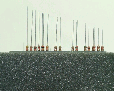
Lay the circuit board on a piece of urethane foam, "pi2vga" label down. You'll see four character labels on the board: they correspond to the colors of the first two bands on the resistors. For example, BnRd stands for the 120 ohm resistor: it's first two bands are brown red. Following these labels insert the proper resistors through the board and into the foam. Some holes don't have labels: leave them alone for now. Trim the resistor leads to different lengths, full length on the connector end of the board tapering to half length at the other end. Here's what it should look like:
![]()
Insert the leads into the Zero's GPIO holes until the Zero is resting on the resistors. A little encouraging with a toothpick helps get the leads into the right holes. Once done hold the assembly together and pull it out of the foam. Solder all of the resistors into the VGA circuit board: it'll be a bit wobbly until some of the resistors are soldered. Insert solid wire (cut-off resistor leads work) through the Zero and on into the remaining holes in the VGA board. These are the ground connections. Solder them to the VGA board. Remove the Zero (you didn't solder anything to it yet, right?) and set it aside. Trim the resistor leads to about 1/4" long.
TIP: If you trim the leads flush before soldering it'll lower the board profile nicely in exchange for making soldering a bit more difficult.
Remove the center row of pins from the connector. If they won't readily pull out they can be bent until they break off. (If you're salvaging from a VGA cable there may be a solder connection to the shell that may need to be softened first.) If the remaining pins will bend without breaking bend them toward the center a bit to hold the circuit board lightly. Solder the connector onto the circuit board, with the narrower part of the connector (pins 11-15) on the side with the "pi2vga" label.
Insert the VGA board into the top of the Zero, connector end away from the SD card socket. Note that the top three holes on the Zero (pins 1, 2 and 4) aren't connected to the adapter. Make sure you get this right or you'll have to un-solder everything. (I'm ashamed to admit that I had to do this, but luckily I had only soldered six connections.) Solder only the two brown-red-brown resistors, the three green-brown-brown resistors, and one of the ground wires into the Zero. This will be enough to verify operation.
CONFIG FILES
In the
/boot/configfile add the following lines:dtoverlay=vga565-3 enable_dpi_lcd=1 dpi_output_format=3 dpi_group=2 dpi_mode=16 display_default_lcd=1You can change the
dpi_mode=16line to get other monitor resolutions. The values are the same as for HDMI group 2.Run
raspi-configand in the Advanced Options section disable I2C and the serial port console.Download
vga565-3.dtbofrom the files section and copy it to/boot/overlays.Reboot and you should have VGA output!
TROUBLESHOOTING
Plug in a monitor or TV to the HDMI port and make sure there's no signal. If there is a HDMI signal you have a problem with the config file or overlays. If there is indeed no HDMI signal test for sync signals on the VGA connector. If you don't have a scope or frequency meter a speaker or headphone can test for the vertical sync signal. It should be about 60 Hz: a nice low buzz. If it's present the config files are probably correct, and your problem is most likely a wiring issue or broken monitor.
FINAL ASSEMBLY
Power off everything and finish soldering the rest of the resistors and ground wires to the Zero and clean up any flux residue. Connect the Zero to the monitor and power up. Log in and open the .png test files in this project's files sub-page. The color bands should smoothly proceed from light to dark. The middle two bands might be the same shade - this is a consequence of the 510 ohm resistor value not being quite correct. This shouldn't be noticeable in normal use though.
SO HOW DOES IT LOOK?
I was pleasantly surprised. At 1024x768 the RGB test pattern showed 16 discrete steps (32 for green), with the exception of the middle. This is due to the resistor problem I mentioned earlier. Photographs looked fine: I might even use this setup to make a digital picture frame!
Super low cost VGA output for the Pi Zero
Similar to the vga666 board, but re-designed for the Pi Zero.
Discussions
Become a Hackaday.io Member
Create an account to leave a comment. Already have an account? Log In.