 Alvaro Villoslada
-
1Step 1
This is a step-by-step visual guide to assemble a Dextra hand. Before starting the assembly, all the mechanical parts of Dextra should be printed. The .stl files are available on the files section, on its Github repository and on Thingiverse.
These instructions are also available in .pdf format.
NOTICE: these instructions are to assemble a Dextra hand v1.0. Future versions of Dextra may have different features with respect to this version and assembly steps may be different to the ones explained here.
-
2Step 2
![]()
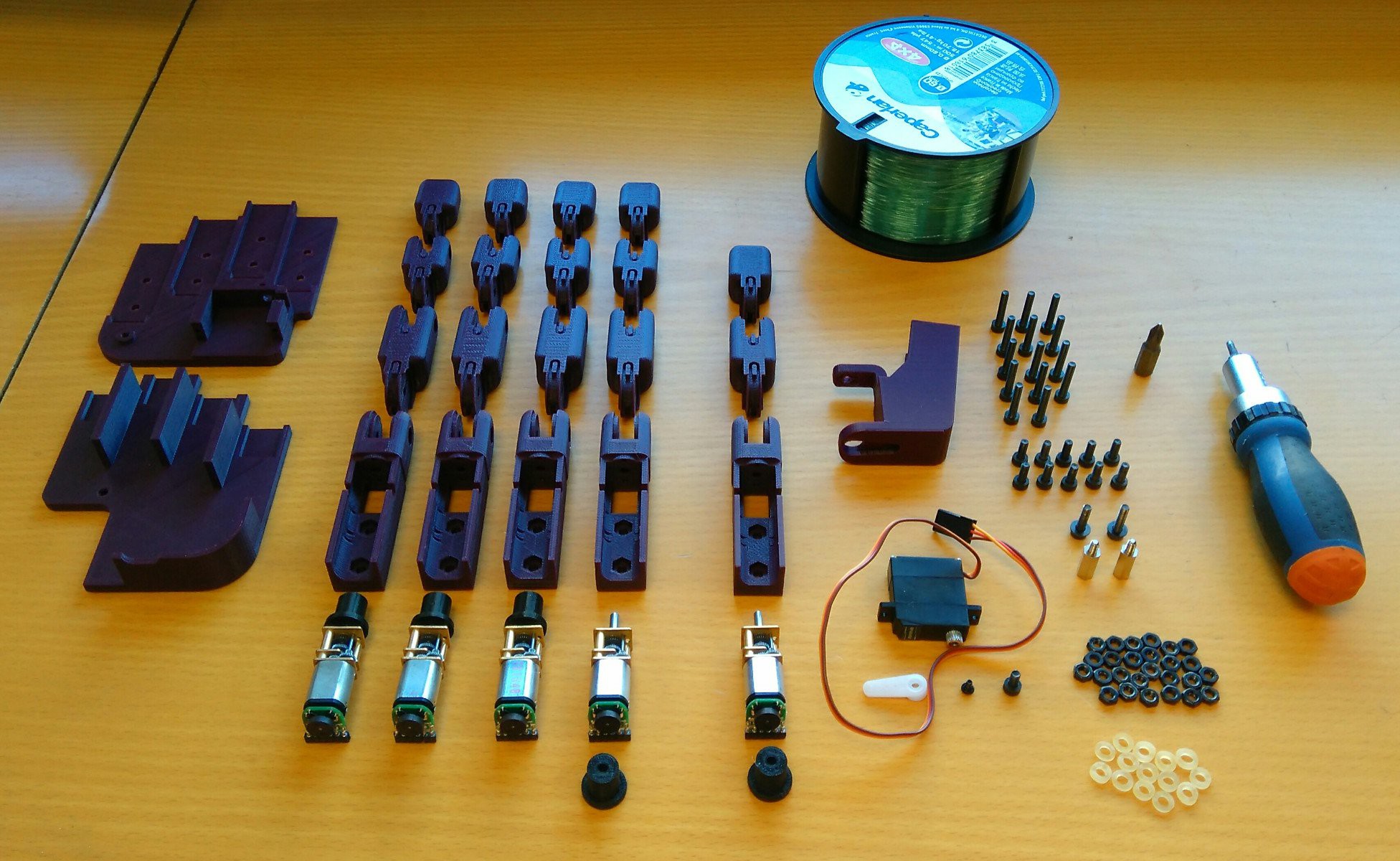
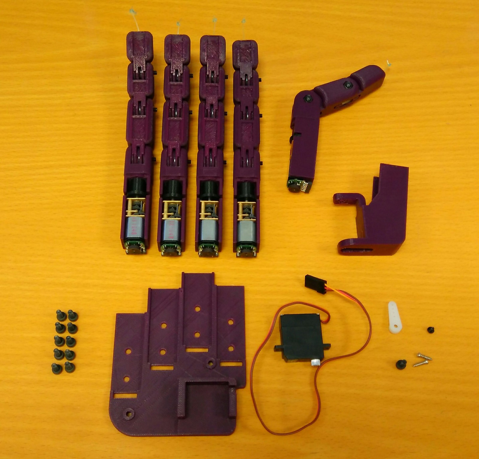
These are all the components needed to assemble a Dextra hand:
3D printed parts:
- 4x finger module:
- 4x motor_holder.
- 4x proximal.
- 4x middle.
- 4x distal.
- 1x thumb module:
- 1x motor_holder_thumb.
- 1x proximal_thumb.
- 1x distal_thumb.
- 5x spool.
- 1x abductor.
- 1x dorsal.
- 1x palm.
Other components:
- 5x Pololu Micro Metal Gearmotor 1000:1 HP with extended motor shaft.
- 5x Pololu magnetic encoder for Micro Metal Germotors.
- 5x right angle female connector (2mm pitch).
- 1x Turnigy TGY-EX5252MG Twin BB Digital Micro Servo.
- 1x fishing line spool.
- 14x small rubber bands (orthodontic elastic bands).
- 14x M3x14 bolt.
- 10x M3x8 bolt.
- 2x M3x12 bolt.
- 1x M3x6 bolt.
- 2x M3x12 spacer.
- 26x M3 nut.
Tools:
- 2.5 mm Allen key (for M3 bolts).
- Phillips screwdriver (for servomotor bolts).
- Needle file or sandpaper (to rework the 3D printed parts if needed).
- Scissors (to cut the fishing line).
- Soldering iron and solder.
- 4x finger module:
-
3Step 3
Step 1 (actuator assembly):
The first step is assembling the micro actuator that pulls and releases the tendons.
To assemble one micro actuator we need:
- 1x Pololu Micro Metal Gearmotor 1000:1 HP with extended motor shaft.
- 1x Pololu magnetic encoder for Micro Metal Germotors.
- 1x right angle female connector (2mm pitch).
- 1x spool (printed part).
![]()
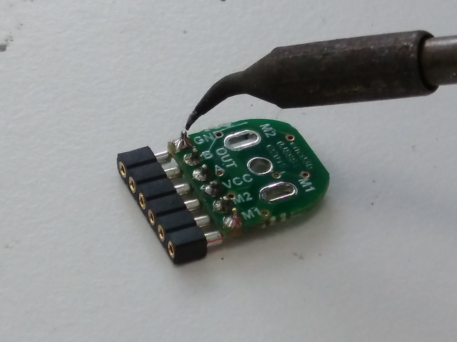
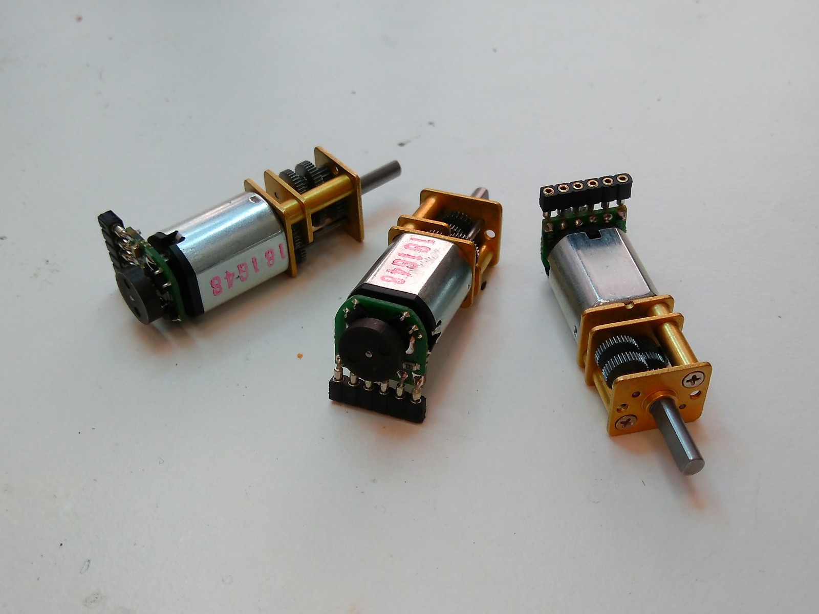
First, we have to integrate the magnetic encoder into the micro motor. Solder the 2 mm pitch right angle connector to the encoder PCB. The pins have to be soldered on the side of the PCB that has text labels and no components, as the image above shows.
![]()
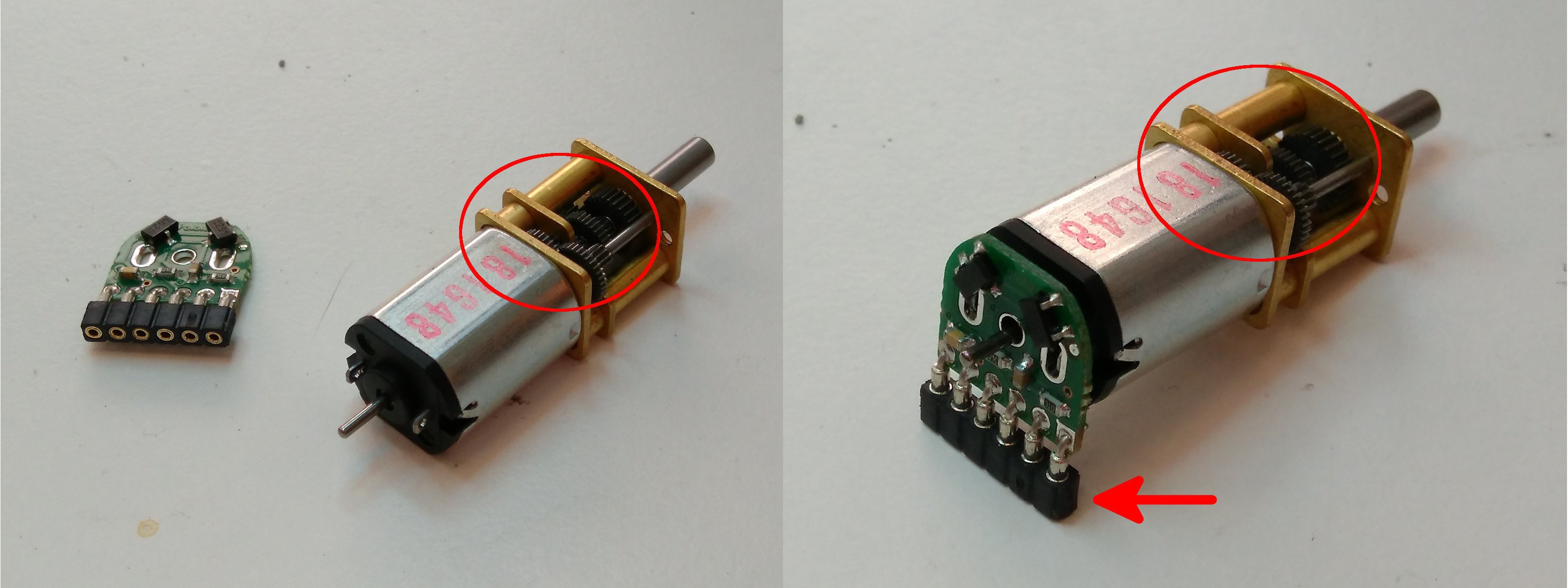
The encoder has to be installed as in the pictures above. Put the encoder PCB on the back of the micro motor with the side that has no components facing the back side of the motor, and with the female pins facing the side of the motor opposite to the one that has a small gap in the gearbox.
![]()
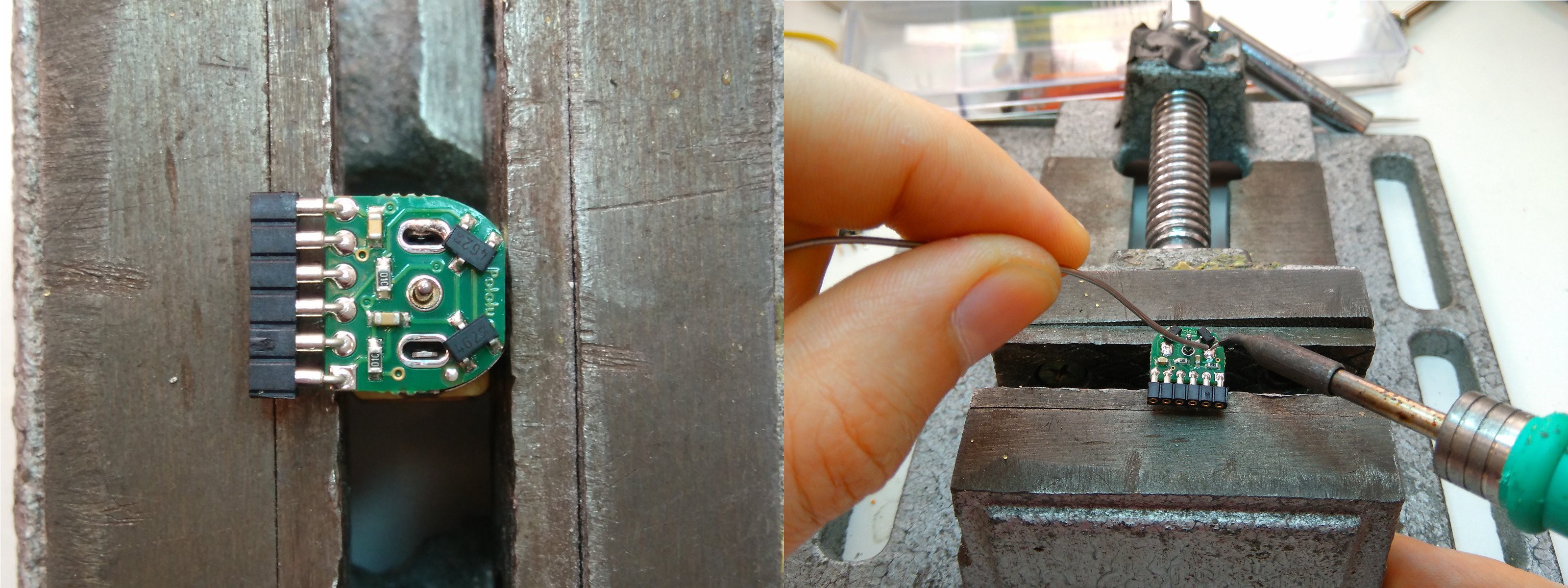
Using a PCB vise or something similar may help securing the motor and the encoder PCB to make soldering easier.
![]()
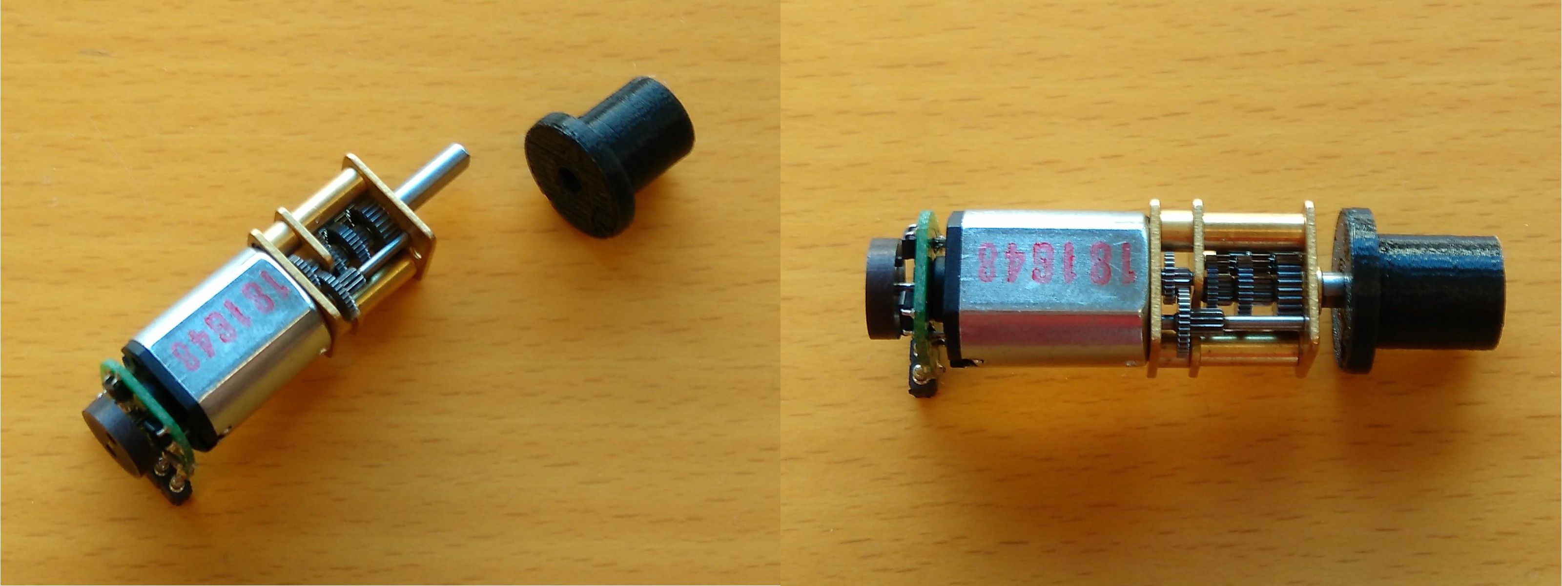
Once the encoder PCB is soldered to the motor, gently push a magnetic disc onto the back shaft of the motor.
![]() Insert the motor shaft inside the spool. One side of the hole of the spool is flat and must match the flat side of the motor shaft. The hole is quite tight, so you may have to exert some force to have the spool fully inserted.
Insert the motor shaft inside the spool. One side of the hole of the spool is flat and must match the flat side of the motor shaft. The hole is quite tight, so you may have to exert some force to have the spool fully inserted. -
4Step 4
Step 2 (finger module assembly):
After we have all the micro actuators assembled, we are going to assemble the finger modules and the thumb module. The finger module is the same for the four fingers, and the thumb module is practically the same (it has two phalanxes and more range of motion on the proximal joint), so these steps are the same for all the fingers.
To assemble one finger module we need:
- 1x assembled actuator.
- 1x motor_holder (printed part).
- 1x proximal (printed part).
- 1x middle (printed part).
- 1x distal (printed part).
- 3x M3x14 bolt.
- 5x M3 nut.
- 3x small rubber band.
- Fishing line.
![]()
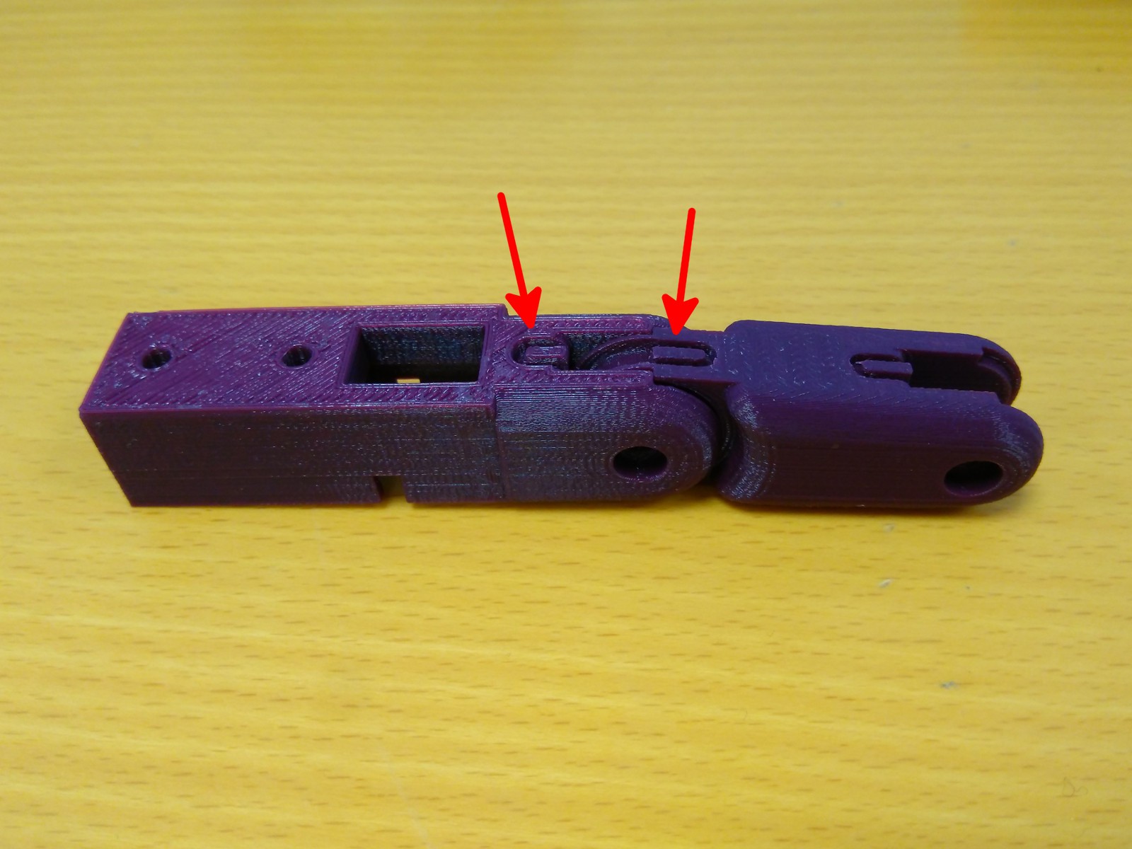
We are going to assemble the first joint of the finger module, the proximal joint. Insert the “male” joint of the proximal part into the “female” joint of motor holder part as the image shows, making the sides with the notch match. Make sure that the proximal part is able to freely rotate without friction. Sand the inner faces of the “female” joint of the motor holder part if necessary.
![]()
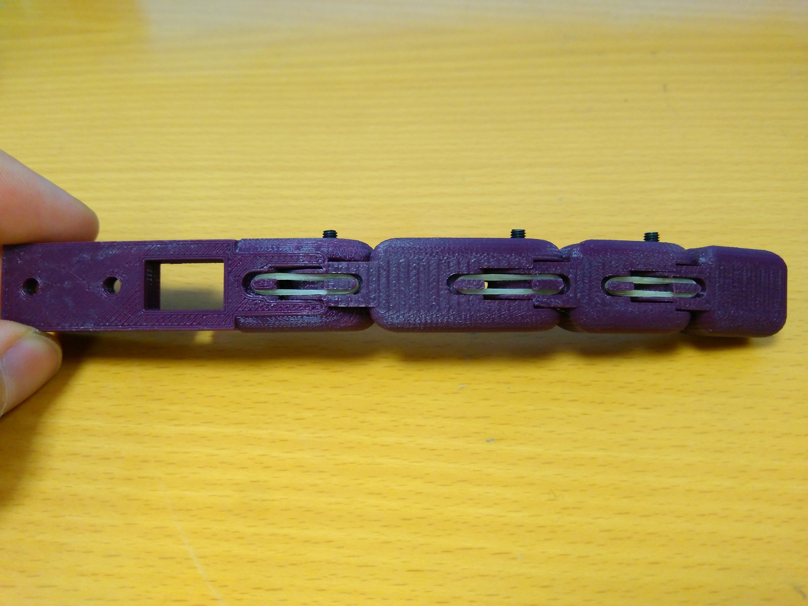
Insert a M3 nut inside its corresponding hexagonal hole. Screw a M3x14 bolt in the M3 nut to join the proximal phalanx to the motor holder forming an articulated joint.
![]()
Insert one end of a small rubber band into the notch of the motor_holder part, stretch the other end of the rubber band up to the back notch of the proximal phalanx and insert it there.
![]()
Repeat the previous steps with the two remaining phalanxes, middle and distal, so you have the mechanical finger assembled.
![]()
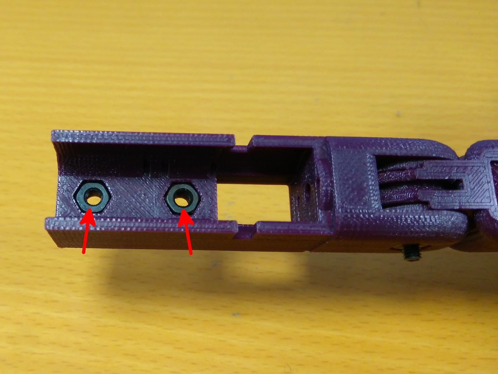
Once the finger is assembled, we are going to integrate the tendon and the actuator into the finger module. Insert two M3 nuts into their corresponding hexagonal holes.
![]()
Cut a string of fishing line of approximately 15 cm long and make a knot in one of its ends. You can put a drop of glue on the knot to make sure it does not loosen. Pass the other end through the small hole in the spool (if the hole is too small, use a sewing pin to widen it). Pull the tendon until the knot touches the spool.
![]()
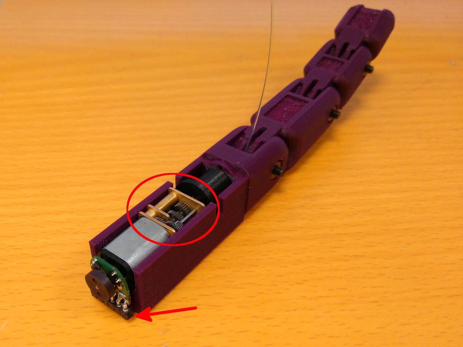
Pass the free end of the tendon through the small hole on the lower side of the motor holder part (see the image above).
![]()
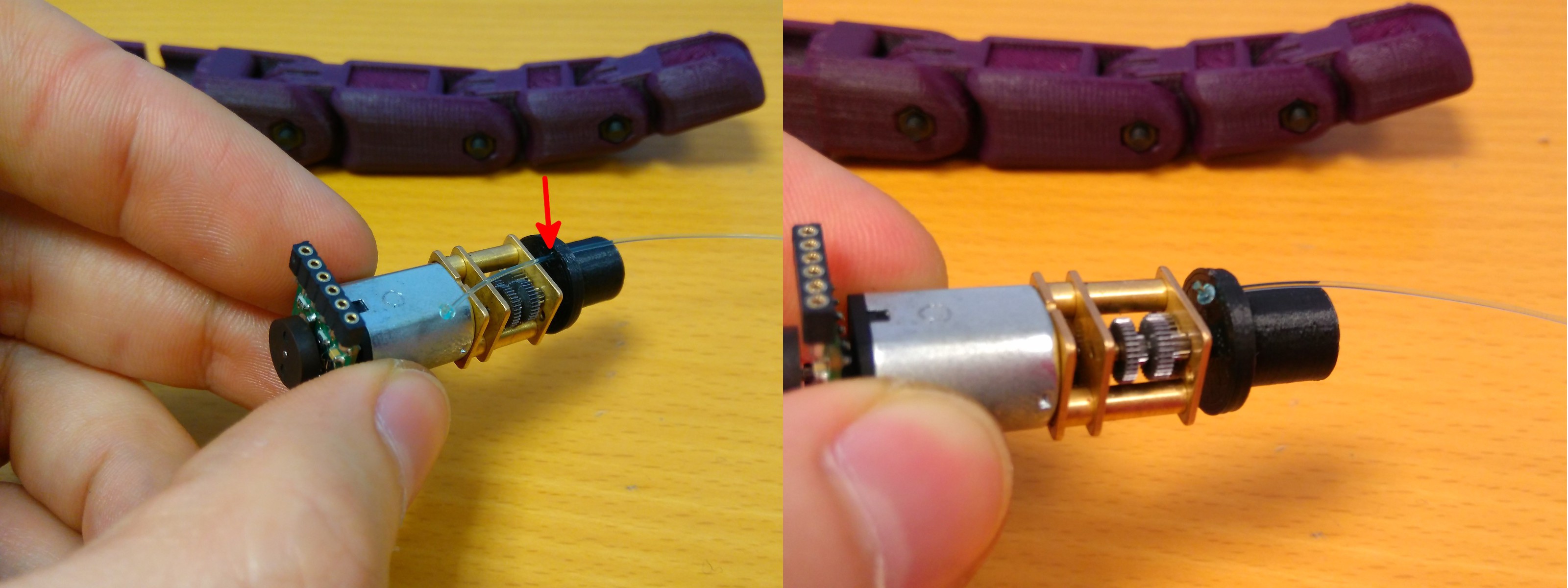
Pull the tendon and insert the actuator into its housing. The actuator has to be installed as in the image above, with the side of the gearbox with a small gap facing upwards and the female pins of the encoder facing downwards.
![]()
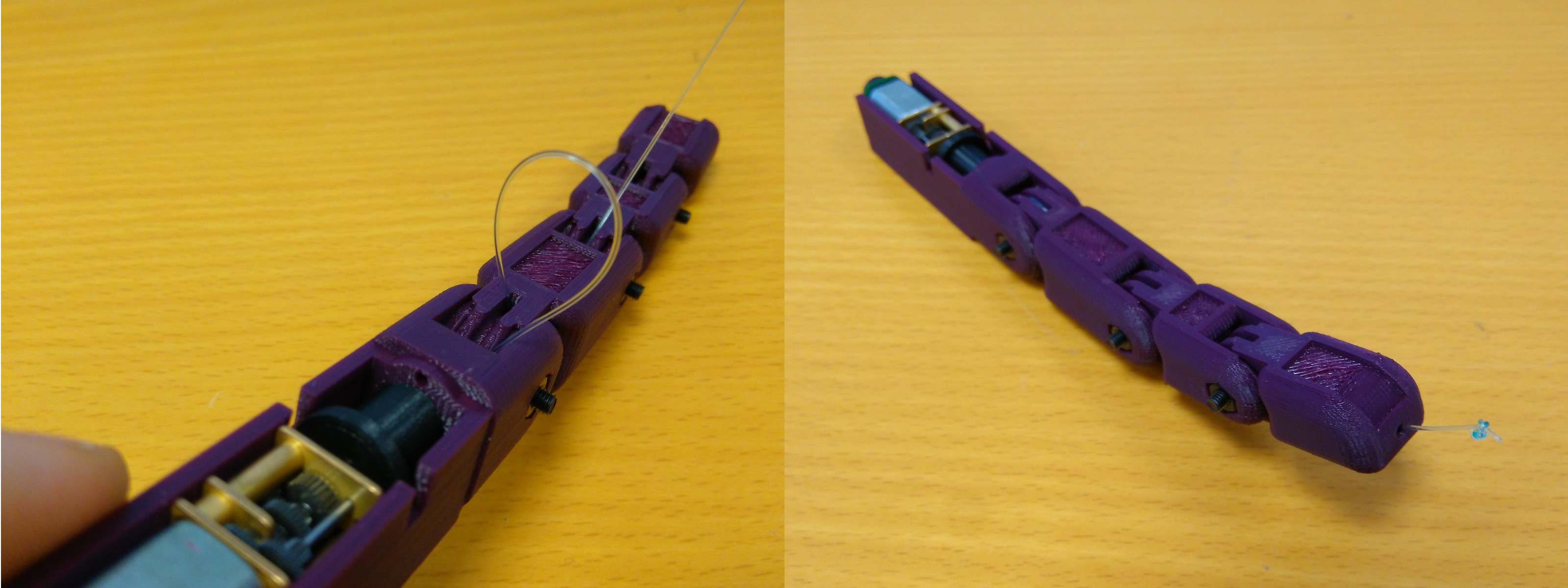
Pass the free end of the tendon through the tendon channels of the three phalanxes until it comes out through the hole on the tip of the distal phalanx. Make a double knot close to the tip of the finger and cut the remaining wire. Once again, you can put a drop of glue on the knot to make sure it does not loosen. Do not worry if the tendon protrudes slightly because, once the hand is assembled, the actuators can be slowly rotated until the tendon is taut.
-
5Step 5
Step 3 (dorsal assembly):
![]()
Once we have assembled the four finger modules and the thumb module, we are going to fix them to the structural piece of the hand, the dorsal part.
For this step we need:
- 4x assembled finger modules.
- 1x assembled thumb module.
- 1x Turnigy TGY-EX5252MG Twin BB Digital Micro Servo.
- 1x dorsal (printed part).
- 1x abductor (printed part).
- 10x M3x8 bolt.
- 1x M3x6 bolt.
![]()
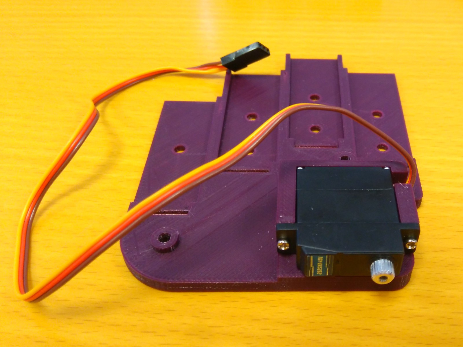
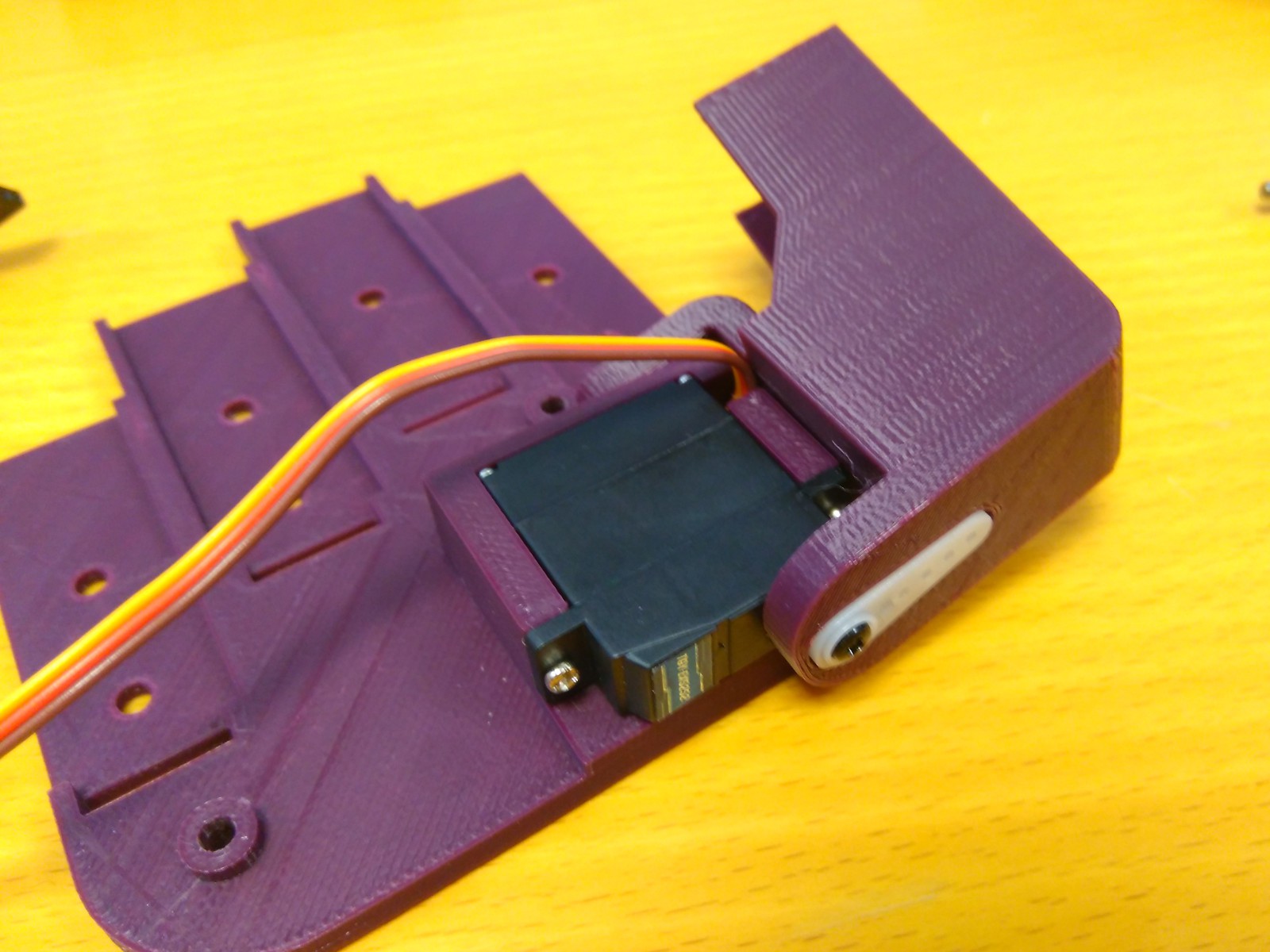
First, we have to assemble the abduction mechanism. Insert the servomotor into its housing as depicted in the image above, with the cable coming out through the small gap in the housing. Fix the servomotor to the dorsal part with the two little screws that come with the motor.
![]()
Insert the servo horn inside its hole on the abductor part and fix it with one or two little screws. Place the horn on the servomotor shaft and fix it with the small screw that comes with the motor for this purpose. Screw the M3x6 bolt through the small hinge of the abductor part to the servomotor housing of the dorsal part.
![]()
Put one finger module on its corresponding place and screw two M3x8 bolts to secure it in place. Repeat for the rest of the finger modules and for the thumb module.
![]()
-
6Step 6
Step 4 (palm assembly):
The last step to have a fully assembled Dextra hand is placing the cover that protects the actuators, the palm part.
For this step we need:
- 1x palm (printed part).
- 2x M3x12 spacer.
- 2x M3x12 bolt.
- 2x M3 nut.
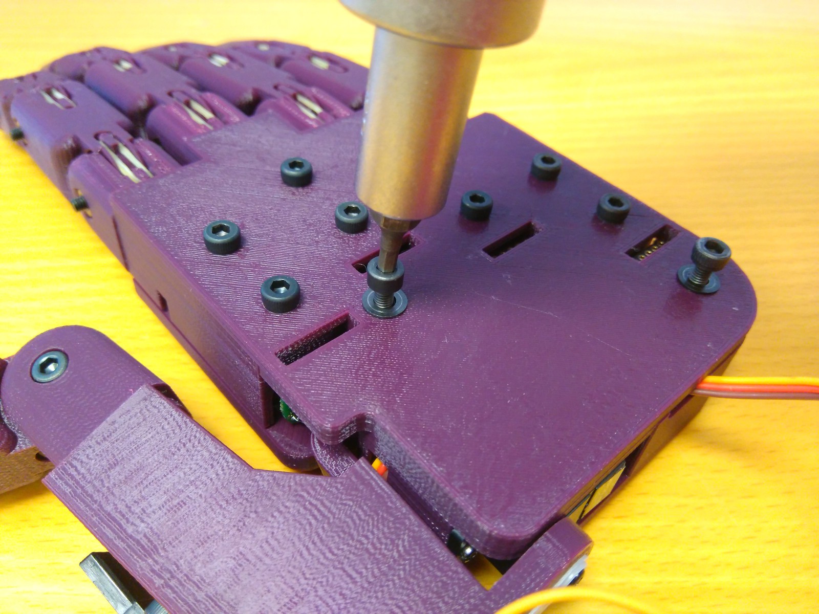
![]()
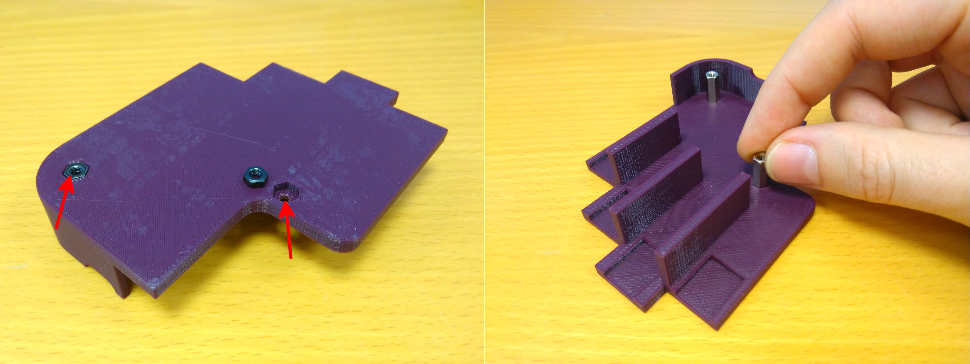
Insert two M3 nuts into their hexagonal holes. Screw the two M3x12 spacers to these nuts.
![]()
Finally, put the palm piece covering the actuators and screw two M3x12 bolts to secure the palm in place. Make sure that the cable of the servomotor goes out through the small hole on the lower side of the hand.
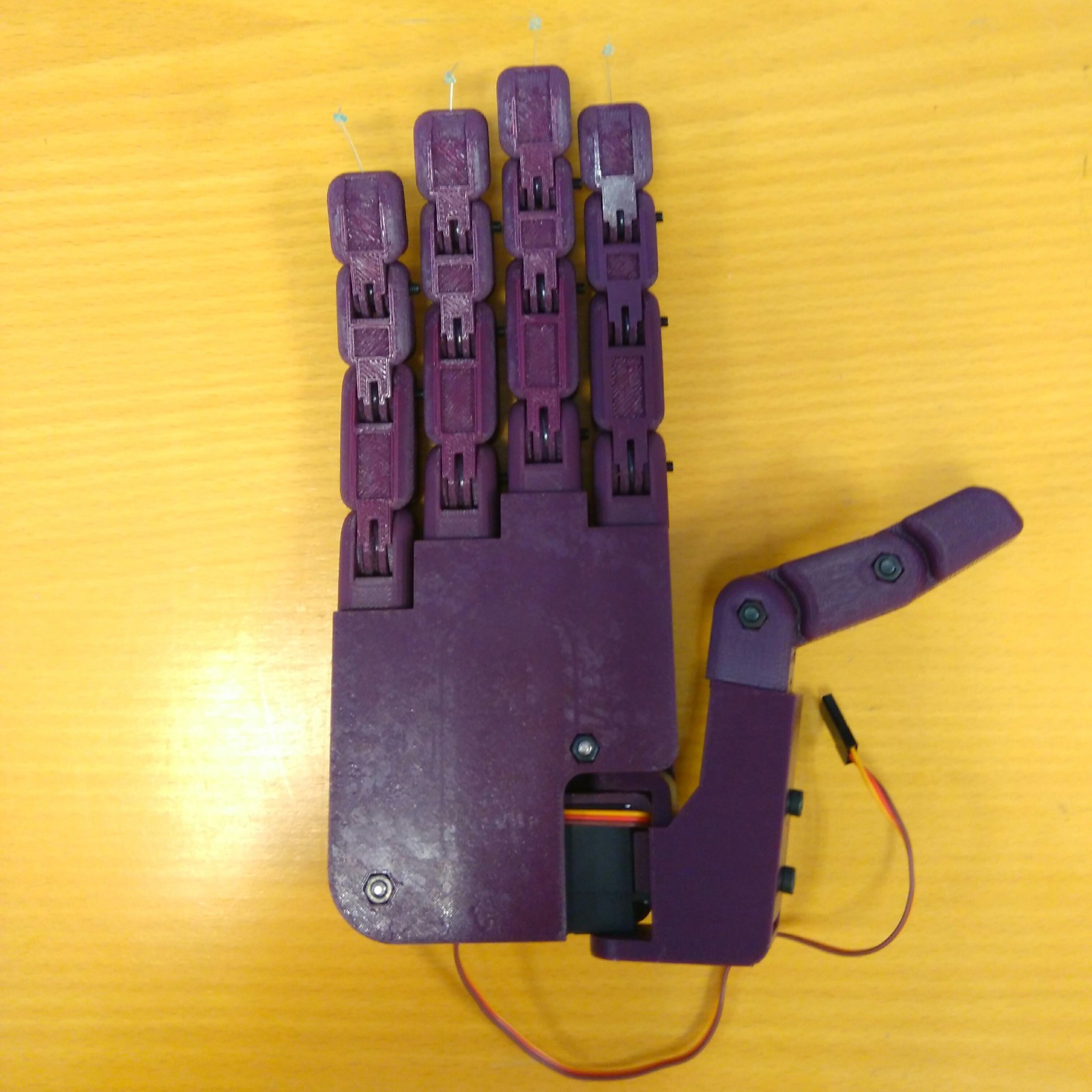
![]()
After following all the previous assembly steps, you will have a fully assembled Dextra hand.
-
7Step 7
Step 5 (connection to the control board):
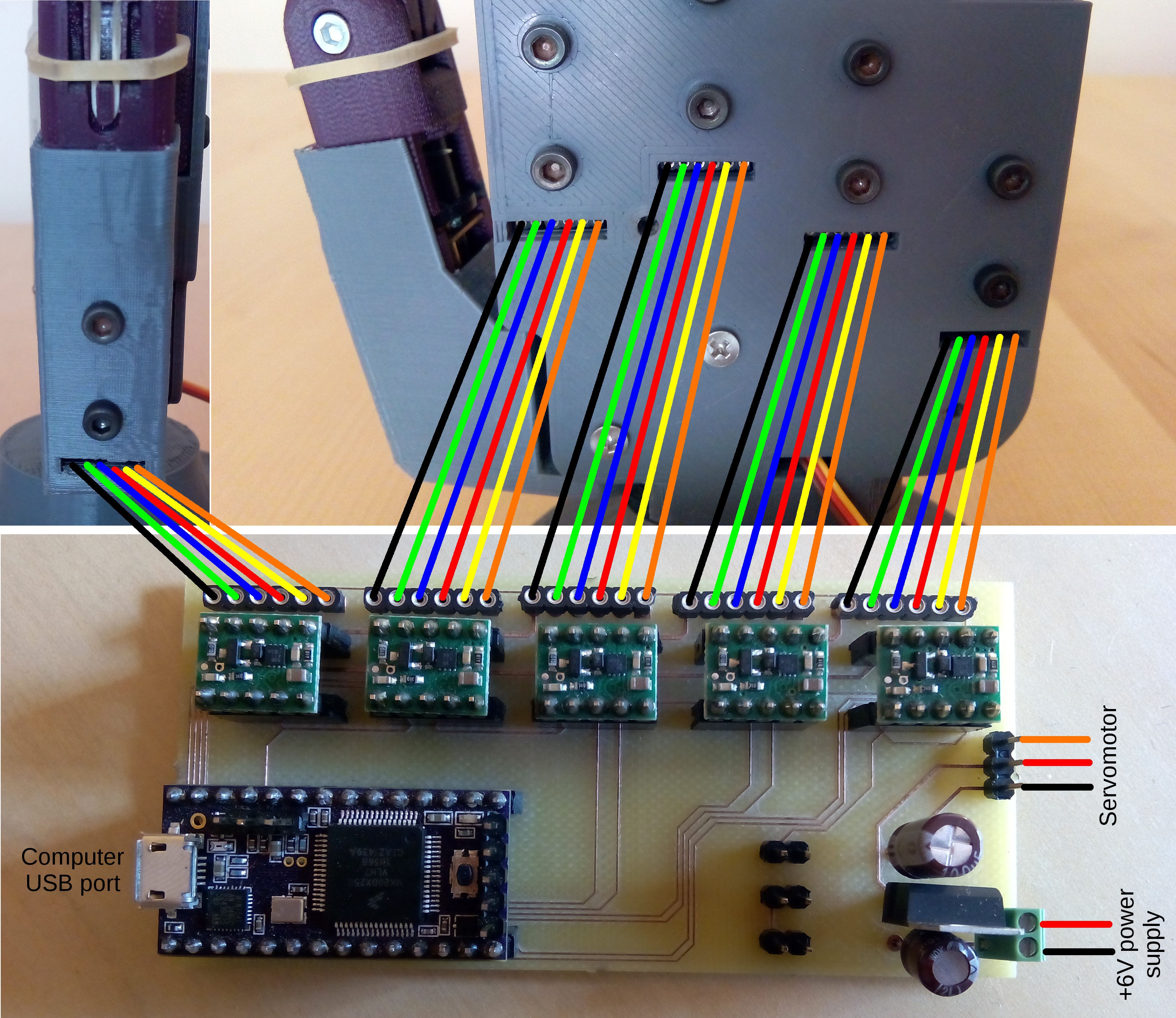
![]()
To be able to control Dextra, it has to be connected to the control board. Connect each finger module and the abduction servomotor as the image above shows. After connecting everything, upload the Dextra firmware (available on the files section and on Dextra Github repository) to the Teensy 3.1.
Finally, you have a fully functional Dextra robotic hand! Now, you can use it any way you want, as a standalone device or integrated into your own projects. The project is completely open-source, so feel free to modify it and share it. Happy hacking!


Discussions
Become a Hackaday.io Member
Create an account to leave a comment. Already have an account? Log In.
I am at a loss, connecting Teensy to 8838 controller is there a wiring diagram available?
Are you sure? yes | no
I have completed most of the hardware required for the project per the instructions PDF.
However am at a loss on how to wire the controller
.In the original a printed circuit board is used. I seem to have no access to that hardware.
So I am trying to use a project Board.
I am a hobbyist with little electrical background, can you help.
Are you sure? yes | no