Audrey Robinel
-
The wheels became a stand-alone project
10/08/2016 at 18:40 • 0 commentsFor this project i had to develop wheels and tyres for 3D printing. I wanted to go farther, and make tracks, increase how configurable everything is, and make everything cleaner, more modular, more functionnal.
I thus decided to create the project OpenWheel, that is as open source as this one, and expands beyond the scope of the orginal project. In the end, i'll generate a new chassis using those wheels rather than the old one.
While this means no direct progress on this robot, it announces upcoming evolution. And this will be a strong evolution for R.Ian.
In the next iteration, it will be much more modular, meaning that you'll be able to change the configuration of the robot in an easier way (i mean, print the chassis, and decide whatever configuration you want, print the corresponding parts, and put them in place. And when you want to change, remove said part, and replace it with a variation).
We'll also address most of the problems R.Ian has currently (main problem is the flimsiness of the wheel due to the servo's axle being, well, flimsy).
This may also cause a slight increase in the cost of the project (more 3D printing to do), but i want to provide a strong base, make it fully functionnal, and kids resistant first. From there, we'll work on decreasing the costs.
-
R.Ian test unit running
03/30/2016 at 05:45 • 0 commentsAs i said in a previous log, the robot has been tested by students for two lessons, and it worked.
However, i never took the time to shoot a video about it. Now it's done :
The video isn't that great because OpenShot was not functionnal on my station, neither was KdeEnlive (i'll install a clean Debian soon in place of my OpenSuse that works but has some bugs now and then).
It's programmed with a simple obstacle avoidance algorithm, and it ran not so bad. Of course, there is a huge amount of room for optimization, but this was just a test program i made in 2 minutes.
I need to change a few things on the board, such as the power switch position (currently, the motors run when USB is plugged).
See you in the next log :)
-
Optional Raspi tray
03/15/2016 at 03:01 • 0 commentsWhere will the Raspberry pi go? For this, there are two solutions : over the electronics, or under it.
If going over, we'll have to make another stage to the robot. It will cause it to have another piece to print, but it makes it easier to upgrade afterwards. You build the basic robot, and if you want, you add another layer with extra stuff.
The second solution is to have it go under the electronics board. In that case, i'd use a 2*20 connector, so that the electronics board would plug directly onto the pi, that would go in it's current position. The plus side is that it's easy to connect the two boards. It is the solution i chose for R.Hasika, as this other robot has a Raspi in all cases. Here, the raspi is optionnal, so we'll have to figure this solution out.
Furthermore, we want to keep costs as low as possible, so we opt for the Pi Zero as a primary solution, so we can think about optimizing space while maintaining easy maintenance, hacking and configuration.
In all cases, i plan on making it possible to use each model of Raspberry pi form factor (B+/2/3, A+, Zero), so two or three tray models.
I think that the pi zero and the A+ make the most sense (low power and cheaper) for this robot, but i want to provide options to users. Anyway, i'll start with the zero tray, then the A+, and finish with the B+ format.
See you soon :)
-
Lipo charger fixation
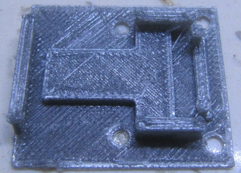
03/12/2016 at 22:55 • 0 commentsI made a new part for this robot in order to hold the lipo charger board presented in the previous log, the TP4056. It has claws to hold the board in place, unlike the previous version that was just a flat part with screw holes and used double face tape to secure it.
Here is what it looks like when printed on my meh quality gray PLA (good enough for structural stuff, but prints ugly) :
![]()
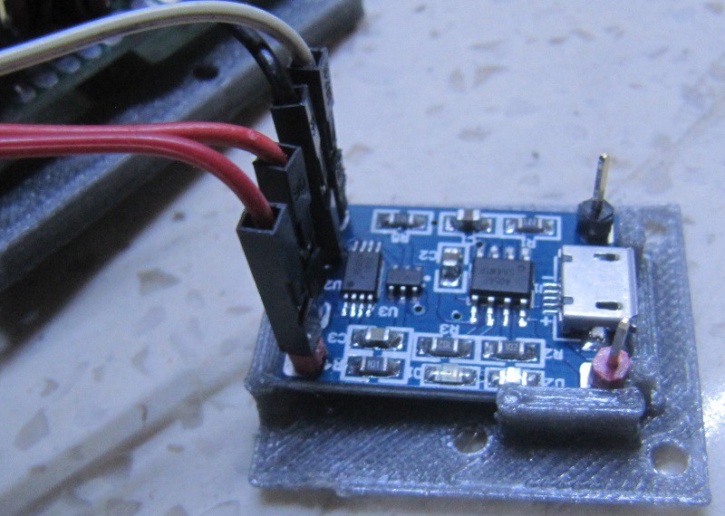
You slide the board in place using a little bit of force, being careful not to break the claws (i broke one, i'll have to improve the design) :
![]()
You can then secure it in place on the chassis using four 3mm screws, with the USB port facing the back of the robot :
![]()
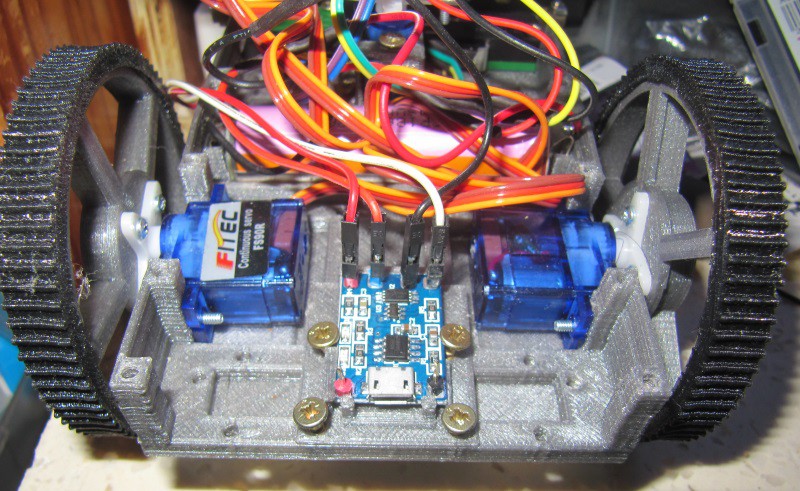
Then you can secure the electronics board again :
![]()
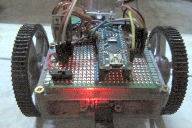
The USB port is accessible, and once plugged in, it begins charging the battery, with a red led on :
![]()
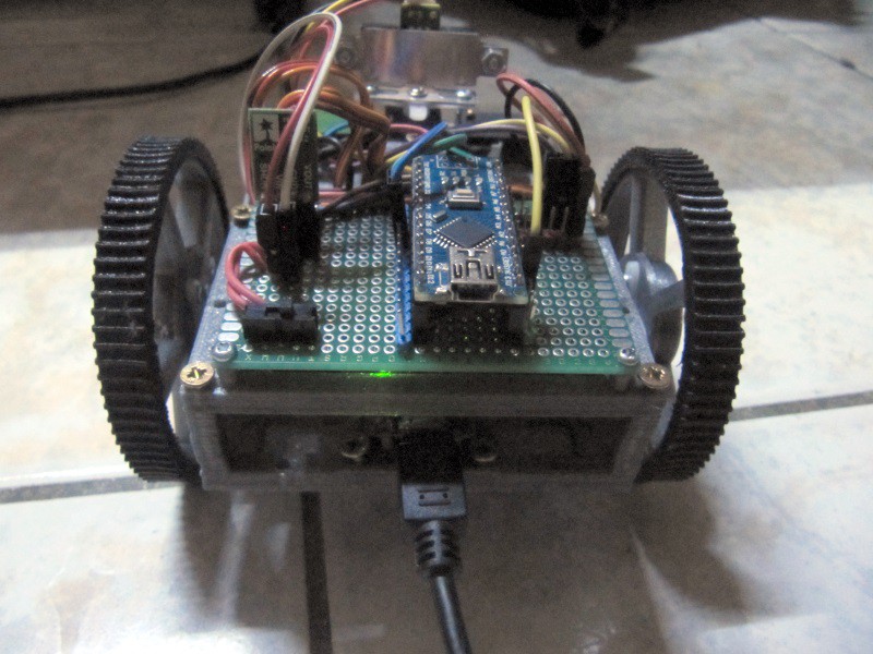
At the end of the charge, the led turns green :
![]()
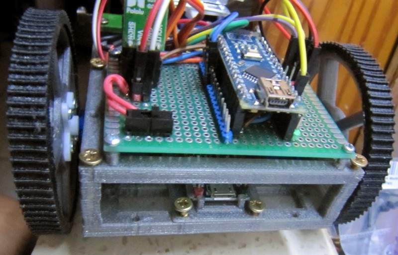
It's also less visible. Anyway, there are input pins if it's necessary to provide 5V by another mean than the USB port (solar panel, charging station, etc).
Now the robot can be used easily without having anything to disassemble to charge it.
-
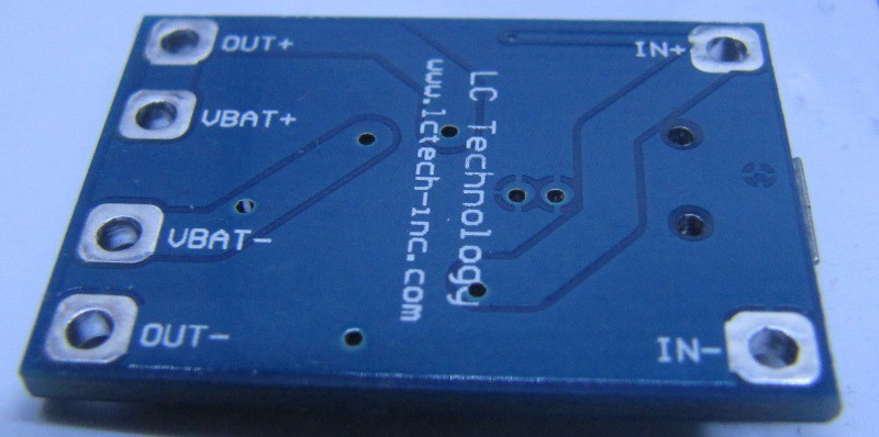
Charge circuit : TP4056 with over discharge protection
03/09/2016 at 01:13 • 3 commentsIn order to make the robot as hassle free as possible, i want it to be charged without removing the battery.
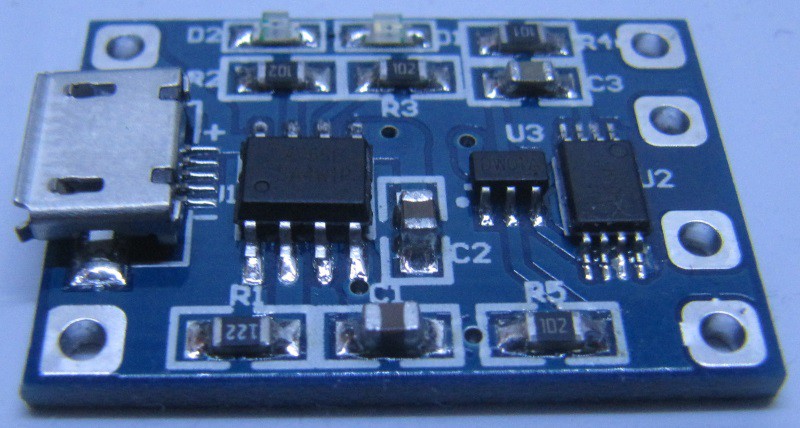
I used pololu zumo robots for teaching computer science, and those have 4 NIMH batteries. Not only the single lipo battery i used provides roughly the same energy for half the mass and a a lower price, but LiPo is simple to charge, hence the vast amounts of cheap LiPo charging boards. I selected not the cheapest, but still a cheap board, at less than 1.5$ a piece, with over discharge protection (and of course over charge protection!).
![]()
I bought a pack of 10 for 13$ with free shipping, from Aliexpress seller Shenzhen factory. This board is based on the very common TP4056 chip. You can see a high quality and detailed review of a more basic version of this board following this link.
Compared to the one tested above, mine adds tabs for load, thus you can have the battery and the load plugged at the same time. The charge maximum output current is given at 1.2A, and it is supposed to support simultaneous charge and discharge.
From the same seller, a single board is less than 2.5$, with free shipping.
The circuit changes in order to add this board are simple : battery wires goes on the charger, and the out + and - goes where the battery wires previously went.
So no modification of the circuit board (that was the plan). This circuit board goes under the electronics board, on the base of the chassis. Room was planed for it, and fixation holes are available. However, i'll have to design a small plate with claws to hold the charger, and with the corresponding screw holes to secure it to the chassis.
![]()
If one wants multiple batteries in a version of this robot, it is possible to do so without increasing charge time by adding multiple chargers and diodes on the output pins. More on that on R.Hasika project, which has 4 lipo batteries in parallel.
Anyway, it also has input pads, so it is easy to add a barrel jack, and why not a 5v regulator so that the robot can be charged with various power bricks with a wider voltage range. This is not something i'll include in the default robot (to keep costs down), but certainly an option or a mod that can be done.
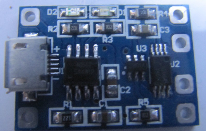
Here is the look of the underside of the board :
![]()
Another use of the input pads could be to have some kind of pads on the robot in order to enable it to go to a charging station on it's own. I'll design such a station and work on this later on.
-
First 2 sessions with 11th grade students.
03/07/2016 at 23:36 • 0 commentsToday, i had my second programming class with 11th grade student, scientific option. Everything went well, and in less than 1 hour, they had coded multiple algorithms to the robot : obstacle avoidance with the contact switches, and then scanning ahead with the servo mounted front sensor.
As i have not done the cover yet, for those two sessions, they used it without it. From this, i learnt a few things.
- As is, without the cover, the robot is not easy to catch while running. Indeed, the easiest place to grab it is the wheels. However, as they are moving, it's probably not great for those small servos;
- the main switch cuts the power from the battery, thus disabling everything, which is good. however, when plugged in USB, the USB powers the servos, and they move. I'll need to either move the switch, add a second one, or add a diode;
- if using only the contact sensors, the robot can get stuck on a chair foot if it hits between the sensors. It works well with walls through;
- the wheels are slightly wider than the contact switch lever. It is thus possible for an obstacle to miss the switch lever, but hit the wheel. A good body design should protect the wheels however.
I will thus be improving this design in the next weeks to solve those issues.
About the students : they are 11th graders from Guadeloupe (a french west indies island), and have no programming class at school. I go there once a week, for an hour, and bring robots for them to program and learn programming. It's not an official class, i'm not paid for this or anything. However, next year, i'll use this robot for my computer science class.
-
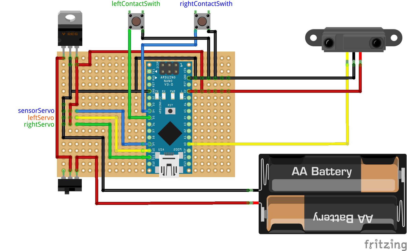
Electronics, Breadboard version
03/06/2016 at 15:13 • 0 commentsIf you don't want or can't solder the electronics board, i have made the schematics for a half sized breadboard version :
![]()
Again, feel free to download the fritzing version of this breadboard circuit on the project's Github.
In order to simplify the schematics, i didn't include the servos, but the labels show where they go.
-
Electronics
03/05/2016 at 06:24 • 0 commentsHere is a Fritzing schematics of the board i used for the first version :
![]()
You can browse the github for various formats of this image, and also download the fritzing file. I'll go more in depth in a next log.
-
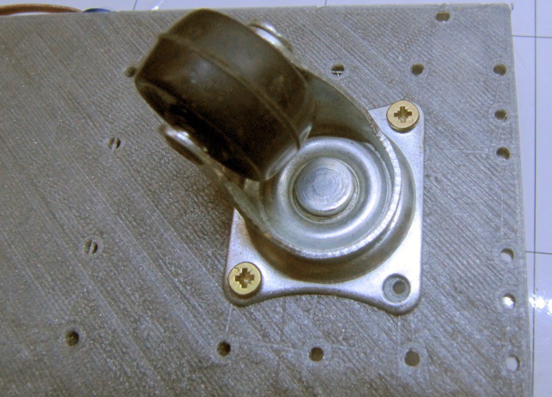
Assembling the robot
03/04/2016 at 05:14 • 0 commentsBefore i make a proper tutorial for this very topic, i'll present here the assembly of R.Ian.
First of all, we install the free wheel on the chassis, using 4 screws:
![]()
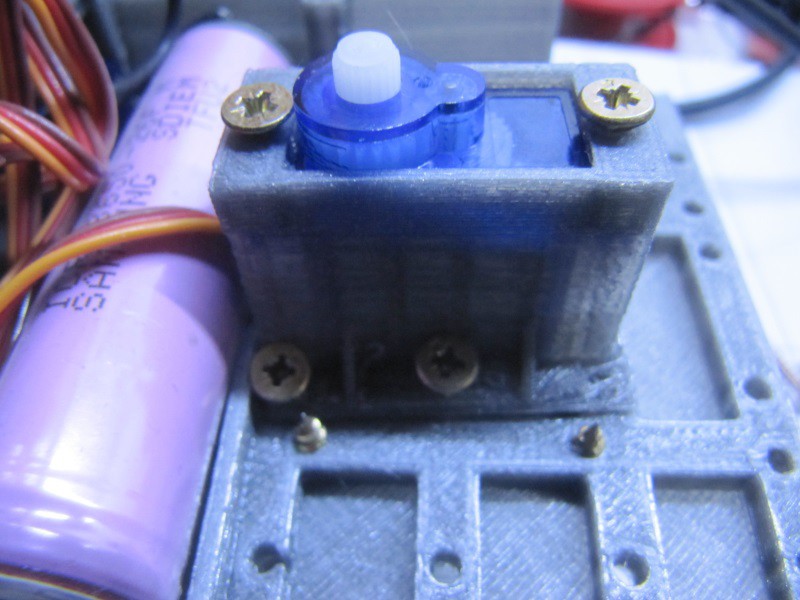
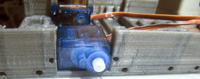
Next, we'll install the front sensor servo (this is optional), For that, we put the servo in the servo holder and secure it in place. Then , we secure the holder to the chassis:
![]()
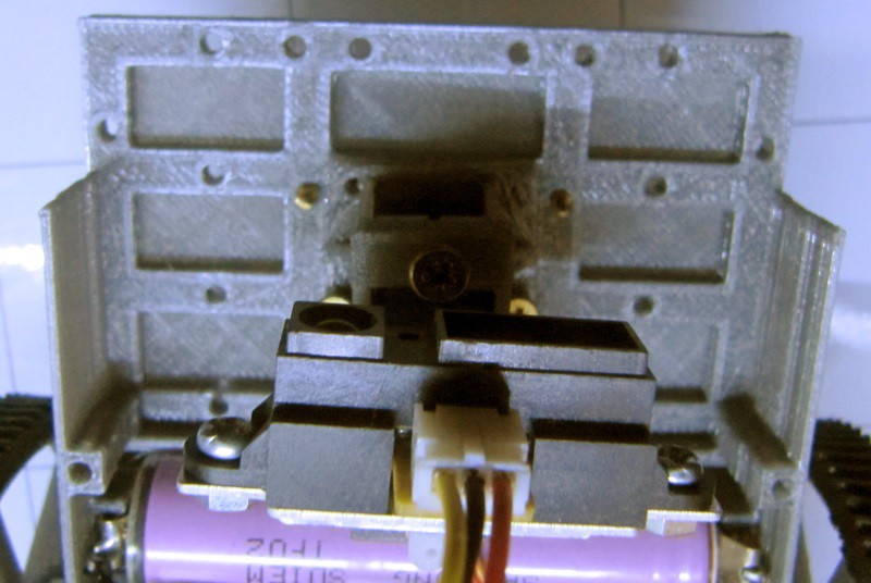
I chose to have the servo axis towards the middle rather than the front so that the sensor is not too much on the front of the robot (to protect it, and IR sensor have a minimal range, often 10cm). We can then secure the sensor onto it, using a bracket :
![]()
When installing the sensor, try to have the bracket as close as possible to the 90° angle (or half the servo max rotation) so that it can easily be centered. In this case, the sensor is a sharp ir rangefinder
After that, another optional phase is to secure the contact switches in front. It is done with just screws. Those sensors are wired to the ground for one pin, and to a GPIO in pullup mode for the other.
Putting the motors in place
Prior to securing the motors in place, they should be calibrated so that the neutral point is at 90° angle (thus immobile). To do so, connect them to an Arduino, and set the position to 90°, then adjust the little screw until they stand still.
Once this is done, the servos can be secured in place :
![]()
The holes should on the chassis should be aligned with the servo ears properly, only 4 screws are needed to secure both motors.
At this point, the battery must be installed, but prior to doing that, the battery tabs must be put in place. For that purpose, follow the detailed instruction on this topic from R.Hasika (those instructions have pictures too). Then the battery should stay in place after applying a little force to get it in it's slot.
The + of the battery goes to the Vin of the voltage regulator, and the - goes to the ground. A switch is a good idea to be able to turn the robot off.
Then, all that is missing is the electronics board. In order to install it, it has to be secured on the electronics plate using M2 screws:
![]()
Then we secure the electronics plate on the chassis using 3mm screws, the USB port beeing at the back.
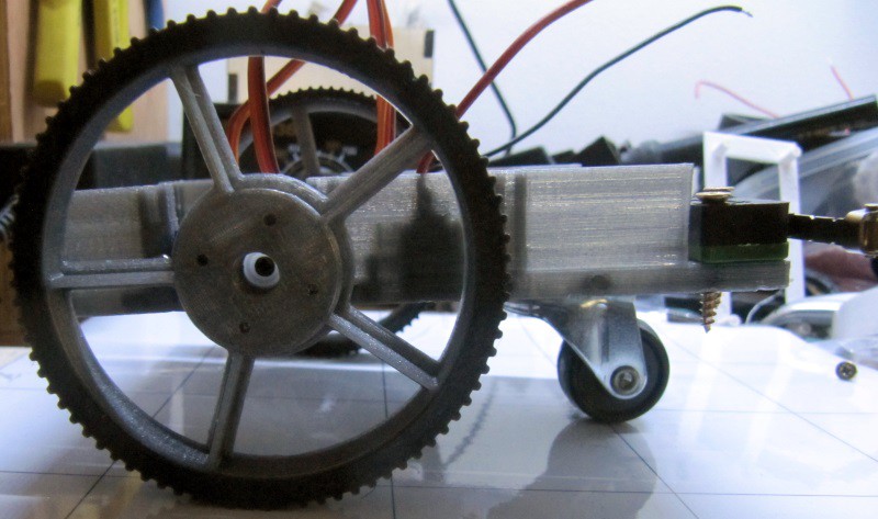
We also screw the wheels in place, using the little screw provided with the servo :
![]()
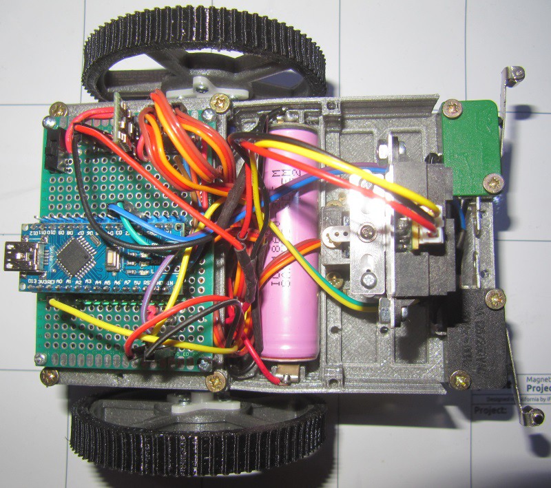
After connecting the cables in place, everything is ready to go :
![]()
Now, using USB the robot can be programmed properly. I'll make a log on the electronics board and wiring later on.
-
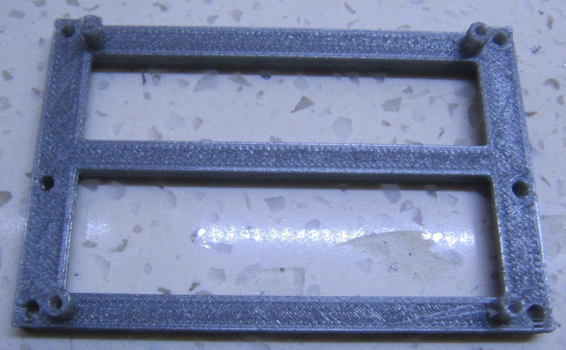
Electronics plate
03/01/2016 at 17:25 • 0 commentsOnce the previous parts are printed, what is missing is a way to secure the electronics to the chassis.For that purpose, i designed this part made for printing in PLA, ABS, nylon or similar material.
It screws to the chassis via 3mm screws, and the main board scerws to it with 4 m2 screws.
Here is what it looks when printed :
![]()
Nothing too fancy here, but with this part, we can assemble a fully functional robot.
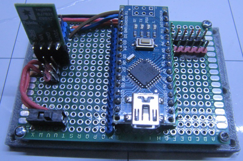
Here is the result with the electronics installed :
![]()
R.Ian, simple and easy built robot for education
R.Ian is meant so be simple to build but have interesting capabilities useful for teaching programming