-
Refining Requirements...
04/09/2016 at 22:34 • 0 commentsWhere I am...
So the short of it is that I have the concept of software interfacing w/ GPIO through relay to trigger the garage door open/close figured out, prototyped, and demoed. I even have a garage door magnetic reed switch on order from Amazon to be delivered sometime next week (I hope) and am fairly confident that will be a no-brainer to integrate for the status detection requirement. My next immediate task is to provide the remote front-end via webapp to interface w/ this system, or perhaps, ditch the webapp entirely and go "all in" w/ OpenHAB.
Initial attempt...
I originally had grand schemes of a live RPi Cam video feed w/ button and status overlays such as suggested by this project: http://hackaday.com/2015/02/23/another-garage-door-opener-this-time-with-security/
However, upon further digging into this project's Hackaday post, Hackaday.IO logs, DeckerEgo blog, and GitHub repository, I'm beginning to think this project doesn't actually live stream video but rather takes a still shot before and after. Regardless, my real hangup is that I spent some considerable time trying to implement it Thursday and got 90% or so the way there, but just couldn't get it to work in the end w/o doing some considerable digging through multiple layers code and httpd configurations.
Nothing against the author of that project. It does look rather slick!
Requirement Refinement...Simplicity.
However, in my project's description/details sections, I left some requirements a bit vague. For instance when I said, "Extract (and enhance) best practices from existing garage door hobbyist projects seen on web and build a version that suites my needs," one major aspect I always intended to incorporate is simplicity. The fewer the complexities, the easier to implement, troubleshoot, share, and upgrade. In my opinion, I view that as a "best practice" as well as "suites my needs." Unfortunately, after working through the example project Thursday, I determined it was just too complex for my tastes.
So, I'm backing up a bit, going more low-level to meet the minimum requirements w/o the fancy overlaying stuff--at least until I can build up to that point. I want as few software dependencies as possible. My goal is to be able to install the latest version of Raspbian "minimum" and provide a list of bare minimum software add-ons needed to complete the effort--no having to install npm/bower/pip to grab stuff outside the debian distros, no additional complex software such as motion/openCV for computer vision--which is a project unto its own right, etc. Again, I seriously do not intend to harsh on anyone else's hard work and awesome project results; it's just not the direction I'm aiming to travel.
Not only that, but I suspect my test w/ hard power off--which resulted in corrupted uSD card--to simulate power failure was extra problematic due to me running an infinite-looped Python script looking for interrupts. So again, I'm looking to simplify and trigger w/ one-shot bash scripts. While this won't help prevent uSD corruption due to the OS/services writing to the card during power drop, at least I'm removing an unnecessary variable.
-
Debounce & GPIO Initial States
04/07/2016 at 20:51 • 0 commentsMy apologies again. Two more business trips out west sank a full 2.5-weeks of time I should have been spending on this project...
Anyway, along the work detailed in the last post, I had to overcome some issues and wanted to include that info here.
Issue #1: Debounce
A well-known ECE challenge to overcome w/ any physical toggle button scenario is that of "bouncing" the button press. So I had to dig a bit for the "preferred" solution for debouncing in Python on the RPi's GPIO. (I'll leave it to others to explain the technical aspects of this--simply google "debounce".) In short, the current version of the GPIO library now includes a built-in solution:
When calling the GPIO.add_event_detect(), add the option bouncetime=X. In my case, X=300 ms seemed to be the magic number.
See https://sourceforge.net/p/raspberry-gpio-python/wiki/Inputs/ for more details on input pins.
NOTE: For the end project, this is not even needed b/c the physical buttons will be replaced by virtual ones via a webpage or some such software app interaction. So why did I worry w/ this at all? Simply b/c I wanted to test this out in the garage w/o lugging a monitor/keyboard outside. I wanted to simply apply power to the RPi, give it a minute to boot up, and then test the triggering mechanism via a button push--also emergency "kill program" button.
Issue #2: GPIO Initial States (plus pull-up/down resistors)
I've already mentioned this would probably be a concern earlier, b/c I saw it mentioned several times by other projects. Many of them blamed the problem on "floating pin", which I attempted to address via the built-in pull-up/pull-down resistors of the RPi--did this via the GPIO.setup lines in Python code posted, using option pull_up_down=.
While that is still a good thing to have (and perhaps even better had I rather used an external 100-ohm resistor to manually implement pull-up/pull-down), that was not really the problem--or at least not in my case. The underlying problem was that when the GPIO library is initialized at the beginning of the Python script, it by default sets certain pins high/low--as it should for clean/known-state programming. However, my situation called for the output pin to be set w/ "reverse logic," if you will; because the relay is ACTIVE LOW, the initial setting of the output pin needs to be initial=GPIO.HIGH. Again, see previous post's code where BCM's pin 18 is setup.
See https://sourceforge.net/p/raspberry-gpio-python/wiki/BasicUsage/ for more details on GPIO initial states.
See https://sourceforge.net/p/raspberry-gpio-python/wiki/Inputs/ for more details on pull-up and pull-down resistors.
-
Bench Test Success - Alpha
03/23/2016 at 04:48 • 0 commentsIn the end, I got everything working in a bench setup--including prevention of unintended relay activation during RPi reboot. Then... I accidentally killed bootup of uSD card by trying to test a power outage scenario--thankfully I had already saved my working Python script to main computer.
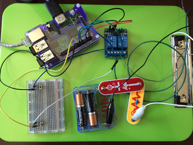
In short, here was my setup:
Components & Circuit:
- RPi2 w/ Raspbian "WHEEZY"
- SunFounder 5V mechanical relay board
- Breadboard
- (2) push buttons
- Wiring
- male-male jumper
- female-female jumper
- alligator clip jumpers
- spare pieces of stranded/solid wire
- 3V battery source
- LED
- 100-Ohm resisto
![]()
Software:
A single Python script named garageCtrl.py as follows:
#!/usr/bin/env python2.7
# Purpose: Testing garage door state toggle via relay triggered by button on RPi. For use in garage w/o keyboard/monitor.
# Button1 - (P23) Kill program
# Button2 - (P24) Trigger relay
# Relay   - (P18) Toggle garage door opener next state

import RPi.GPIO as GPIO
import time

GPIO.setmode(GPIO.BCM)
GPIO.setup(18, GPIO.OUT, initial=GPIO.HIGH)
GPIO.setup(23, GPIO.IN, pull_up_down=GPIO.PUD_UP)
GPIO.setup(24, GPIO.IN, pull_up_down=GPIO.PUD_DOWN)

def my_callback(channel):
  print "Rising edge detected on port 24, in the main thread."
  GPIO.output(18, False)
  time.sleep(0.1)
  GPIO.output(18, True)

print "Press Button #1 (P23) to kill program."
print "Press Button #2 (P24) to trigger relay."
#raw_input("Press Enter when ready\n")

GPIO.add_event_detect(24, GPIO.RISING, callback=my_callback, bouncetime=300)

try:
  print "Waiting for falling edge on port 23"
  GPIO.wait_for_edge(23, GPIO.FALLING)
  print "Falling edge detected. Here endeth the second lesson."
except KeyboardInterrupt:
  GPIO.cleanup()  # clean up GPIO on CTRL+C exit
GPIO.cleanup()    # clean up GPIO on normal exit
Raspbian Configuration:In order enter a "ready" state automatically upon applying power to the RPi, I tweak the OS configuration as follows:
- At bottom of .bashrc file, added line: sudo ./garageCtrl.py
- Modified /etc/inittab line 1:2345:respawn:/sbin/getty --noclear 38400 tty1 with line 1:2345:respawn:/sbin/getty --autologin pi --noclear 38400 tty1
- Changed boot-up to console rather than X-Window via raspi-config tool.
These changes cause the RPi to bootup headless (w/o GUI resource overhead), automatically login, and finally execute python program to listen for button presses that trigger the relay/garage door opener.
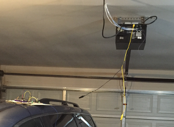
Garage Door Test:
It works on the bench lighting up an LED, but just for validation-sake also confirmed it worked in the garage by replacing the Snap Circuit node w/ leads to the garage door opener's contacts 1 & 2.
![]()
-
Relay Determination
03/20/2016 at 20:33 • 0 commentsA rather productive day yesterday. Lots of experimentation and trial-n-error. Lots of web/eBook researching...
In the end, the Solid State Relay (SSR) was latching when activated rather than just momentarily shunting the garage door opener contacts. It did toggle the garage door to open, but I was afraid to leave it activated in a latched ON state through the entire door transition (akin to taping the wall button down.) So I yanked power after a few seconds.
I double-checked the garage door opener's control contacts 1 & 2 w/ a multimeter and read both ~36VAC and ~16.7VDC. I have some ideas to run down on this, but for now it simply made more sense to go back to the tried-n-true mechanical relay and try to figure out how to overcome the initial bootup activation problem.
-
Solid State Relay Board
03/19/2016 at 18:07 • 0 commentsMy latest relay board solution is based upon information from this Instructable. It uses the "SainSmart 5V 2-Channel Solid State Relay Board for Arduino Uno Duemilanove MEGA2560 MEGA1280 ARM DSP PIC" for about $16 via Amazon.
Specs:![]()
- (2) Solid State Relays
- Power Supply: 5VDC 160mA (all channels ON)
- Input Ctrl Sig:
- 0-0.5V = LOW
- 2.5-20V = HIGH
- Load: 75-264VAC, 0.1-2A
- Phototriac isolation
Concerns:
Output/Load/Switching side of relay on works as expected for AC loads. If DC load, it latches when activated, waiting on AC cycle to reset it--which of course never happens.
- (2) Solid State Relays
-
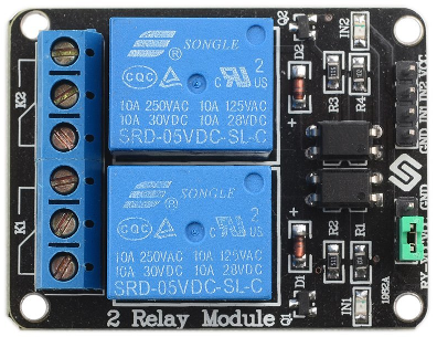
Mechanical Relay Board
03/19/2016 at 16:41 • 0 commentsThis was the first solution I was planning to implement based upon this Instructable. It is the "SunFounder 2 Channel 5V Relay Shield Module for Arduino UNO 2560 1280 ARM PIC AVR STM32 Raspberry Pi" for about $7 via Amazon.
Specs:![]()
- (2) High-current Relays
- Input: 5VDC 15-20mA driver current
- Output: 28-30VDC 10A / 125-250VAC 10A
- Relay output status LEDs
- Optically isolated
- Active LOW
Concern:
The major drawback to this module is that it is Active LOW, meaning this relay triggers from NC to NO by driving the input to GND. Depending on application, this isn't a big deal to invert logic in controller, or it may even be the desired solution. However, w/ this particular project, if the RPi were rebooted (due to power flicker/outage, etc.) it would possibly trigger the garage door to activate during the bootup process. Not a secure solution--particularly if we are away/asleep when this happens, and it opens the door.
If you do enough reading in the Instructable's comments and this product's Amazon customer reviews, that's a common observation/complaint. Granted, folks overcame this by inverting the signal w/ a transistor or implementing a pull-up resistor, or implementing some other such additional physical circuitry. In my case however, I prefer to keep the entire system as compact/simple as possible--meaning fewest number of boards/modules.
If my next relay option doesn't work out, I may return to this board and first try the pull-up resistor technique. This is most likely the correct reasoning here, b/c when the RPi is booting up, the pins are floating somewhere between HIGH and LOW, and it's just the luck of the environment conditions whether the relay will be triggered or not.
- (2) High-current Relays
-
Back at it & Relays...
03/19/2016 at 16:02 • 0 commentsUnexpected delays this week... Got back from business trip late Monday night, only to spent the next two days playing Mr. Mom while wife suffered through a bad case of stomach flu. Two more long days of work at the office, and finally I have a moment to get back to this project...
Anyway, I need to post about the relay(s) I'm using. Back many months ago, I bought a 2-Channel 5V mechanical relay board based upon one of the garage door projects I was researching at the time. However, by the time I got back around to seriously implementing this project, further research suggested using a different solid state relay board b/c it defaults LOW rather than HIGH (like the mechanical relay did.) There are a few reasons why this might be a better solution, and I will discuss those in future logs.
Anyway, I've got one of each and will determine over time which implementation works best for my situation. A new post on each relay to follow...
-
Side Note - Garage Door Trickery
03/13/2016 at 23:42 • 0 commentsNot really pertinent to this project, given the model of opener I have, but a tangential point of interest non-the-less...
At first read through the manual, I mistakenly thought that my garage door opener could utilize either the 1-button (M350 model, which I have) or the 3-button (M3100 model) controllers. I was excited by the prospect of adding the ability to turn on/off the opener's light, b/c not only do I worry about whether or not I forgot to shut the garage door, but I know for certain that I somewhat regularly forget to turn off the separately wired garage lights until I'm already backing out in the car. If I could control the opener's light, then I would not use the other light source when leaving in the wee hours of the morning. So this started me on a research path of "how do you control 3 functions w/ 2-wire analog channel?"
According to what I found, two scenarios are likely:
- "AC hackery" using diodes. In this method, the 2-wires running to door button is 12 or 24 VAC. By utilizing a properly rated diode, one could create 3 different shorts across the terminal pair:
A. Open/Close signal = full short/dead short
B. Light On/Off = pos single-phase short via diode in one direction
C. RF Lock = neg single-phase short via diode in opposite direction - Voltage/Resistance difference. In this method, each trigger option is implemented via higher/lower resistor values for each button to create different voltage drops at the terminals.
I suspect scenario 1 is more likely, but unfortunately (and upon closer reading) my garage door opener does not support this feature set. So I won't be testing this out since it's not worth me buying a new garage door opener--otherwise, I could save myself the trouble of this project altogether and by a turn-key solution w/ Internet control already built-in. :)
Still, just thought I'd put this out there for others to consider in their future projects...
- "AC hackery" using diodes. In this method, the 2-wires running to door button is 12 or 24 VAC. By utilizing a properly rated diode, one could create 3 different shorts across the terminal pair:
-
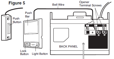
Garage Door Opener
03/13/2016 at 23:12 • 0 commentsI'm working w/ a 2006 Chamberlain AccessMaster 1/3 HP M350 garage door opener rated at 120VAC 5A 60Hz. This particular garage door opener provides three (3) contact points (screw terminals) on the back for hardwired signaling (e.g., push-button momentary switch, safety reversing sensor, etc.)
Screw terminals 1 & 2 are for 2-wire, 24V low voltage wiring to wall-mounted controller. Terminals 2 & 3 are for safety reversing sensor pair (IR beam "eye") mounted at the base of garage door tracks.![]()
(Note: My model utilizes the single push button controller. The more expensive model in this manual uses the 3-button controller.)
-
Catching up on notes...
03/13/2016 at 22:21 • 0 commentsSo far, I've spent several hours researching existing projects and culling the better ideas into a Moleskine notebook (I'm a bit old school when it comes to project journaling). I've also been researching my particular garage door, possible garage door control signalling schemes, and refreshing my knowledge/understanding of the RPi2's GPIO. In addition, I've bought a few parts that I suspect I'll need.
Long story short, I'm wrapping up initial planning/research and will be ready to start actual development/integration/testing when I return from a business trip I'm currently on. Before I left, I managed to run a couple RPi I/O tests on simple stuff for proof of concept and took a few readings from my garage door opener's input points.
Perhaps I'll come back to this post over time and list the links of projects/references that I actually ended up using. (New to Hackaday.io, so it all depends on if the environment allows me to update an old post.)
For now, let me start a new post on garage door stuff...
Home Automation - Garage Door Opener
Extract best practices from existing garage door projects. Build version that suites my needs; eventually integrate into other HA efforts.