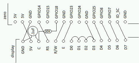
I picked the GPIO's used to make wiring simple and also have a nice look. Here's the wiring diagram: crossed lines are NOT connected together:

Solder the wires (I used 24 gauge solid wire salvaged from a telecom closet at work), the resistor, and the capacitor onto the display (per the diagram) and bend them to look like this:

Here's a detail on how I mounted the capacitor. It was a tight fit:

Slip some insulating tubing on the 5V, RS and R/W wires like this:

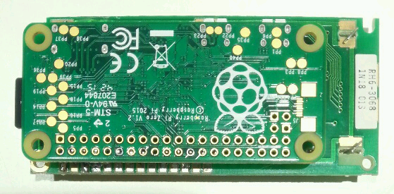
Then put the Zero on top and solder it on. It should look like this when you're done:

Finally use some hot glue or silicone caulk under the connectors to support the other edge. Don't get any on the processor chip:

Here's what it looks like from the back. Quite a tidy little package indeed!:

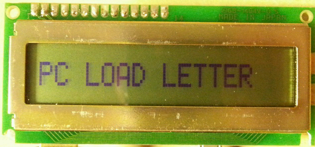
And here's what it looks from the front. Bonus points if you recognize the movie reference:

THE SOFTWARE
There's plenty of code for driving the display from Python, but I decided to write a proper kernel module. Mostly because I enjoy writing modules, but also because I don't want to learn Python. It really wasn't hard, just a variation on one of my existing modules. The only problem I had was this particular display is configured kind of funny: It's a single line display, but must be initialized as two line. Then, to write to the right half of the display you must jump ahead 40 character positions. (I remember reading about this in the past, but when I went looking I couldn't find the reference, so I can't credit it.) This wasn't hard to handle in the module once I realized what was needed. It just took a little trial and error to figure it out.
THE KERNEL MODULE
Don't be afraid of compiling modules: my modules page has easy instructions. Module source is in this project's files sub-page. Module compile and usage is straightforward. Once the module is loaded there will be a /dev/hd44780 device which you can write to. All character values are passed directly to the display to make special character display possible. The display is cleared and the write address is set to the first character each time the device is opened.
The kernel module can be easily altered to drive other HD44780 displays with different numbers of lines and/or different line lengths. There are comments in the source that should point the way. If you've modified the kernel module and are using a two line display, you'll have to pad the first line with spaces to write to the second line.
Adjustable contrast is obtained by using the PWM0 output (use the gpio utility to set a value), although my particular display ignores the contrast setting.
MAKING A USB DISPLAY
I used Linux's gadget mode to make the Zero emulate a flash drive, backed by an image file. Basic instructions are here. I then wrote a small shell script that periodically read-only mounts the image file and copies the contents of the display.txt file to the display device. To use it you plug the assembly into a computer using a micro USB cable and edit the display.txt file on the emulated flash drive to change what shows up on the display. The assembly is back-powered via the USB cable, so no power supply is necessary. That's it - one display unit, one cable, any computer!
REFERENCES
A HD44780 kernel module which I studied while writing my module.
HD44780 wikipedia entry
HD44780 Datasheet

Lol HAHAHA "PC Load Letter?? WTF is a PC Load Letter??" Love the Office Space reference. LOL