To make the experience fit your profile, pick a username and tell us what interests you.
We found and based on your interests.
Now, guess what I did. I took the electronics and installed it into the housing. Crazy. I don't want to rule out the possibility that I'll build another one soon, but for now, this project is completed.
And the back side with all the connectors and LEDs..
On the back side, there are line-in and line-out connectors, which are wired directly to the Bluetooth module. The two USB ports are wired to the DC/DC converter and serve for charging smartphones.
The device is charged by plugging in a 5V 4A wall charger. The speaker self-reliantly turns off for charging and the four LEDs underneath the connectors indicate the charging status of the four LiPo cells. Each LED represents one of the four LiPo cells. The four red-lit LEDs show that all four cells are currently charging.
Once a cell is full, its corresponding LED turns blue. Since all cells are charged independently, the whole 20 Ah bank charges within 5 hours, but it can happen that some cells finish earlier than others.
Once all LED's shine blue, all cells are full and the speaker is ready to go.
With 2 x 16 W (RMS) / 2 x 11 W (sine) the speaker gives a room-filling and full sound for it's size. The bass is certainly the most impressive part, but the two-way car speakers also deliver clear and brilliant highs, it sounds better than what I'm used to from portable speakers. I'm surprised how well the parallel charging hack worked, with the fast parallel charging trick and dual-color indicator LEDs the whole thing is quite useable.
My wife already received her new portable Bluetooth speaker, and so far she seems to be very happy with it. As said, I might continue this project with a new version, so if you have any ideas, shoot me a comment.
Meanwhile I've managed to fully assembled the charging circuit I described in the previous log. I backpacked it on top of the four LiPo cells.
I also added an external board with four common anode RGB LEDs to display the status of each cell on the back of the speaker. "blue" means full, "red" means charging.
Below you can see one of the Axicom FP2 relays, it's super tiny but still can take high voltages. However, the switching current is 2A max., which is the bottleneck for this charging circuit, so per specification, the maximum charging current of an individual cell is also 2A max., and the maximum current to draw from the entire pack is also 2A max. Fortunately, the TP4056 can only deliver 1A and the amp will also draw no more than 2A.
The TP4056 modules were surface mounted to the perfboard with their input and output pads. I also cut the connection to the onboard LEDs and bodged the LED signals to a pin header for connecting the external RGB LED board.
The wire bodging was tedious. Definitely an argument for having some nice PCBs made next time I use this circuit, and then of course skipping the modules and designing my own TP4056 circuit. Below picture also shows how the charging circuit sits on the LiPo cells.
In the tradition of this project, also the amp was prepped on a perfboard, because well, why not. AB amps are dying out anyway.
The DC/DC converter was also attached to the perfboard it to save space. It supplies power to the KRC-86B bluetooth module and USB charging ports.
I tried to route this as clean as possible, but then thought I might as well add a MOSFET to turn the amp on and off from the bluetooth module's 'EN' output, which goes HIGH when the module has successfully connected to a host device. So the right lower corner is a bit messy :)
The KRC-86B bluetooth module sits on a pin header attached to the amp, which makes it easier to mount the whole thing in the shell later.
The TDA2030A are attached to a somewhat a bit too large heatsink from the drawer. If I measured everything right, it should fit though.
Now that the paint has dried, it's time to talk about circuitry.
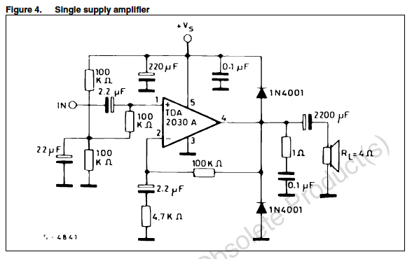
No doubt, a class D amp would surely be more efficient and provide some additional hours of fine music plus would save some space in the housing for other cool things. But well, I still got several TDA2030A, throwing them away would also not be very efficient. Also, they offer superior THD, and the circuit is so simple I can just solder it to a perfboard.
Some of you may doubt that you can/should charge four LiPo cells with four cheapo TP4056 modules in a single application. I also had doubts, but my tinkerplementation works well so far. It's based on the tiny but powerful Axicom FP2 relays.
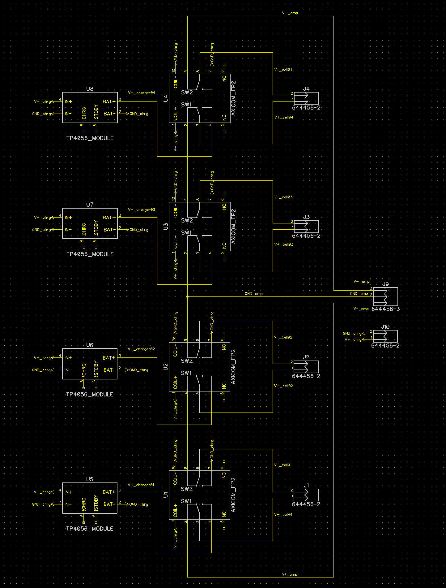
During charging, this simple circuit isolates each battery and connects it to its own TP4056 module using the two changeover switches of one Axicom FP2. All TP4056 modules share a common ground and charging power input, but of course only charge one cell each. The charging power input also magnetizes the coils of the relays, so when no charging voltage is applied, the relays fall back to their idle state, connecting all cells in series to power the amp with +/- 7.4 V or 14.8 V respectively.
I als made sure within the expected failure modes, there's nothing bad that can happen:
The circuit is damn simple, very cheap and can be assembled on a breadboard with ease. It charges four cells simultaneously with a total current of 4A max. Unfortunately, that's also the end of the benefits, downsides are that you have to charge in silence and the cells are unbalanced. So not very sophisticated.
The TP4056 has two open collector status indicator outputs for i.e. attaching LEDs. I figured I could use four RGB LEDs with common anode to indicate the charging status of each cell. While charging, a LED would light up red, once finished it would light up blue. The green remains unused for now.
Have I mentioned the cells are unbalanced? That could be easily fixed by adding an Arduino to the project and configuring it to use some MOS-FETs and dummy load resistors to balance the cells while in use. The Arduino could also read the charging status from the TP4056 modules and display them in a bargraph or on a display, or instead of an Arduino something more powerful could be used, too.
Also, of course, there is still the option of adding a class D amplifier, as suggested in the comments. A class D amplifier would save a lot of space in the housing. That space could be filled with boost converters for higher sine power, or with a Raspberry Pi to do cool streaming stuff, and maybe a touch display, or just more batteries. Maybe I'll add all of those improvements in the future, we'll see.
As you can see, the printed and assembled shell is now nice and shiny. Since I didn't want to expose my DSLR to the extremely dirty and dusty work of sanding, filling, sanding again and color spray painting, you may be content with looking at the following images of the finished results.
Actually, I'm quite happy with it. I used only what I had in the workshop, leftover racing filler, leftover sparkling black spraypaint, leftover clear varnish. The spay filler really did it's job in filling up the glueing marks and smaller imperfections of the print.
I test wise inserted the USB charging and audio connectors.. everything seems to fit.
It's not as tedious as it reads, but patience is key. Those are the steps to get there:
For this project, I commited pretty much any crime in design for 3D-printing. No flats, lots of overhangs, thin shell (2mm). So the only way I could print this without excessive use of support structures was cutting the design into pieces that could be printed selfsupporting, thus maintaining a nice surface quality.
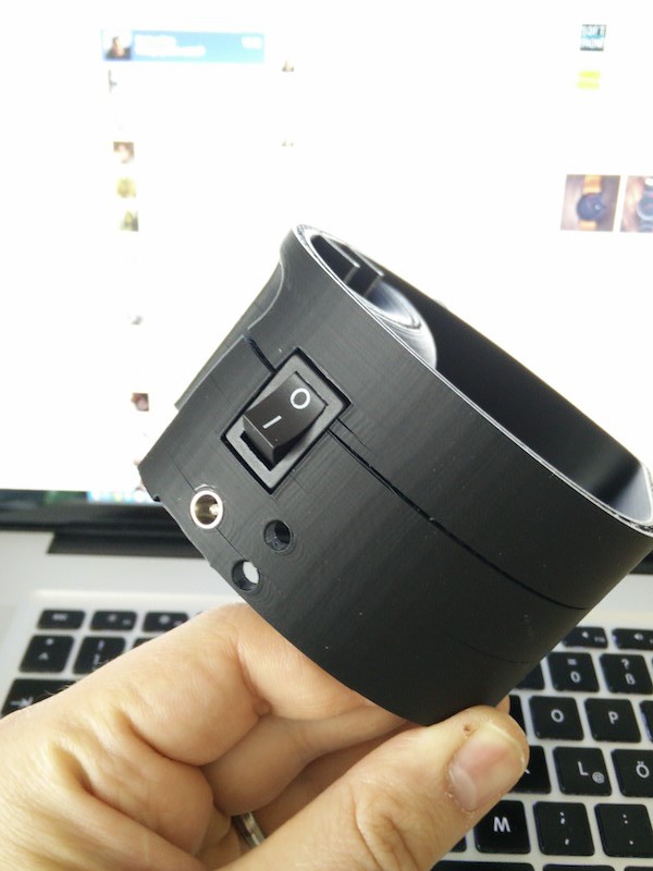
I tried smartABS and PET-G for this. In the first trial, I printed the smartABS at 255°C at 50mm/s. The bananaing was minimal, but the result (see below photo, the cracks were not caused by the switch) had many thermal cracks and would've required massive fixing.
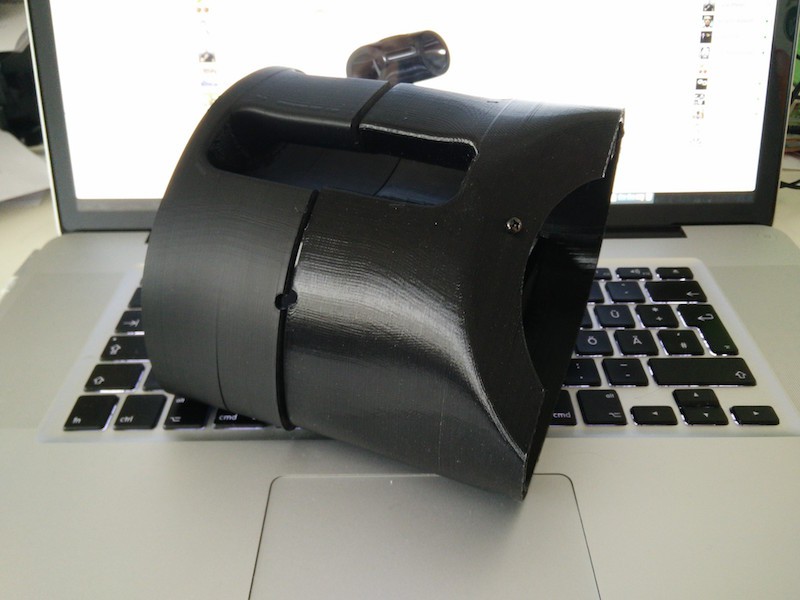
Then I tried the PET-G, which I bought for printing large objects with less bananaing. Unfortunately, even after iterating down to 240 °C, wich is kind of the lower end in layer bonding, as well as different retraction settings, the PET-G was still very oozy and blobby. The nozzle ran into hard bumps of dripping plastic over and over again, which caused this print to fail, too (see right half of below photo).
So I went back to smartABS, which is still my favorite material, iterating upwards in temperature. I ended up printing the shell at 280 °C with 50 mm/s, way above the maximum specified temperature of smartABS (270 °C), but this improved the layer bonding enough to give me nice, banana-free shells without cracks. Below you can see my printer in its natural-wood habitat printing a center pice of the shell.
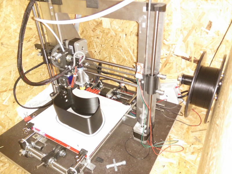
After about 30 hours of printing, I had all the parts crack- and banana-free.
The five parts were then glued together using aceton and acetone-ABS slurry. Then scotch tape holds it together until everything has hardened.
Create an account to leave a comment. Already have an account? Log In.
Great project! Dumb noob question, but what are those connectors you are using on the board where the wires from the LED breakout come in? Havent seen those before and they look super useful!
I'd like to press 'like' a million times on this! I like everything about this project! The charger hack is.. hackworthy :) The boards are very nicely done and the casing - don't get me started. just wow! such a finish on a 3d print? who'd thought.
congrats!
That case is fantastic! really good looking! I have built a small amp based on the MAX9744 (2*20W) maybe that could be interesting for you? (http://embryonic.dk/wordpress/?cat=26)
Hi! Why 4 TP4056? If you're wiring them in parallel, that's up to 4A on 5V, which is a lot =) If you're wiring them in series, that can even get unsafe if you're not switching cells with relays... Guess you could really use a good Li-ion charger board. You could even disassemble one and just put there =)
Hi! Excellent question. I figured I could use a little intermediate circuit between the LiPos and the TP5056 modules which allows for charging each LiPo pack individually at 1A each (yes, 4A in total, charging the combined 20 Ah pack within 5 h). When no charging voltage is applied, the intermediate circuit self-relianty connects all cells in series to obtain about 15 V for the amp. I'm using AXICOM FP2 relays for that, I have tons of them. The downside is that I have to charge in silence. I'll document that once the project progresses more. First I have to make that shell nice and shiny :)
Hmm. I personally would research more on multiple cell chargers, since if your circuit fails, I'm not sure the failure will be graceful - and those multi-cell chargers are relatively cheap and quite powerful. Also, you can make a simple relay (or FET) power source switchover circuit for device to work while battery's charging =)
You should also account for cell balancing. If you don't the cells will balance on their own which would lower your play-time..
Thanks @Jan! Yes, totally agree. But the TDA2030A still has a good sound and I still have a bunch of them lying arround :)
I know that part-number ;)
Tried a Class-D amp recently and it was *way* more complex, but maybe the newer ones...
Doing a hifi class D with drawer parts would actually be a fun challenge ^^ still got some 555s here..
Nice project idea! But why bother using class A/B amps anymore? Just buy an class D amp off ebay or wherever. Much much more efficient. You could go with one or two 5Ah lipo packs then. You won´t even need a heatsink: I´d go with a TDA7492 or Tripath TA2024 module. These are under 25EUR usually...
Ah, missed the reply button again, see above comment :)
Become a member to follow this project and never miss any updates
Hello,
What did you connect the AGND to on the krc board?