Close
0%
0%

ps2pi

A simple PS/2 keyboard interface for the Pi Zero.

Similar projects worth following
Need to free up the USB port, or just love your old Model M keyboard? With two resistors, an LED, a connector, and a kernel module you can connect a PS/2 keyboard to the Zero's serial port.

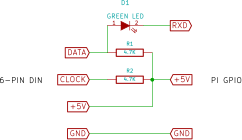
HERE'S THE SCHEMATIC

HOW IT WORKS

You'll notice in the schematic that the keyboard clock line isn't connected to a GPIO, so how can this work? After a bit of testing I've found you can read a keyboard with a serial port running at a custom speed. This works because the data output of the keyboard is actually standard 8 bit data, one start, one stop, odd parity serial, as long as the keyboard clock pulses are regular and consistent (it was on the keyboards I've tested). The only downside is the baudrate varies for different makes/models of keyboard.

The only components you need are two resistors as required by the PS/2 spec, and an LED to drop the 5V keyboard data output to something the Zero can handle (kind of an unusual use for an LED, but it works beautifully).

And of course you need a kernel module. It's workings are pretty simple: set up the serial port and an interrupt handler. Then on each interrupt get a byte from the UART, translate using a table, and stuff the resulting keycode into the Linux input subsystem.
ps2pi.ko

Kernel module for kernel version 4.4.48+

ko - 8.30 kB - 03/04/2017 at 01:03

Download

ps2pi.c

Kernel module source

x-csrc - 6.06 kB - 12/29/2016 at 19:56

Download

ps2pi-overlay.dts

overlay source

DTS Audio - 1.21 kB - 05/03/2016 at 03:43

Download

ps2pi-overlay.dtb

compiled overlay

Digital Talking Book - 1.14 kB - 05/03/2016 at 03:43

Download

ps2pi.sch

KiCad schematic

sch - 2.00 kB - 03/06/2016 at 14:45

Download

View all 6 files

  • 2 × 4.7K resistor
  • 1 × Green LED
  • 1 × 6-pin mini-DIN socket

View all 7 project logs

  • 1
    Step 1

    BUILDING IT

    You'll need a mini DIN 6-pin socket to connect to the keyboard. It can be scrounged from an old keyboard adapter, or you can eliminate it altogether by cutting the connector off the keyboard cable and wiring it directly to the interface. Refer to the PS/2 interfacing link at the bottom of this page for pinout information. The LED can be replaced with another color as long as the forward voltage at low current is 1.8-2.1 volts. The resistors are also not critical - any value from 2000 to 10,000 ohms should work, 1/10 watt or larger.

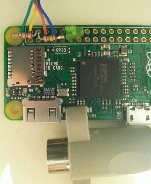
    Solder the components directly to the GPIO connector holes like I did in the picture below. All connections are to the outside row of holes on the Zero. The LED's cathode is bent down and soldered in the fifth hole, the anode is soldered to a resistor. The keyboard data line is also soldered to this junction. The keyboard +5V line is soldered in the first hole, and the keyboard ground is soldered in the third hole. The keyboard clock line is soldered to the other resistor. Lastly the free ends of both resistors are bent round and soldered in the second hole on the Zero.

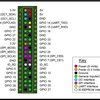
    Make sure nothing connects where it shouldn't - a bit of paper or tape under everything will prevent this from happening. The picture is a bit fuzzy, but if you refer to the schematic and pinouts for the Pi it should become clear.

    IMPORTANT: The keyboard should not be hot-plugged: connect or disconnect only when the Zero is powered off. Make sure you wire it correctly or you may fry your Zero, or the keyboard!

    Source code is available under the files subpage. Don't be afraid of compiling kernel modules: easy module compiling instructions are available under my piModules page.

    The device tree overlay ps2pi-overlay in the files subpage needs to be copied to /boot/overlays and dtoverlay=ps2pi needs to be added to /boot/config.txt. It will automatically load the kernel module as long as it's in the proper subdirectory in /lib/modules and depmod has been run while you are in that directory.

    The overlay needs be configured with the clock divisor for the UART. To find this, connect the keyboard and power up. Then compile the ps2test program and run it as root. Follow the onscreen instructions to find the needed dividers. You'll have to edit the overlay source to set these values, then compile it. The overlay as supplied in the files section will work on an IBM Model M keyboard.

    You also need to disable the serial console. The easiest way is to use raspi-config, and disable Serial under Advanced options.

    The keyboard mapping is for a US keyboard. Other keyboards may need changes to the key map table in the overlay.

    There is no reverse communication from the Pi to the keyboard so the keyboard lock lights do not function.

    Here are links to sites that helped me in this project:

    Dom and Gerts GPIO access example

    Linux kernel module programming HOWTO

    The Linux USB input subsystem part 1

    PS/2 keyboard interfacing

    kbd FAQ

    Raspberry Pi forum project page

View all instructions

Enjoy this project?

Share

Discussions

profepcpi wrote 04/11/2017 at 22:04 point

Hi,

i'm trying to do it but i have a problem. 

i've maked all the hardware and compiled the module and when i try to run the ps2test to take the frequency, asks me for semicolon key, i press it and after 2 seconds program ends without response.

 Can you help me please?

  Are you sure? yes | no

j0z0r pwn4tr0n wrote 03/02/2016 at 19:48 point

Will this work in combination with your Pi VGA board? Would be an excellent way to reuse components that are just collecting dust

  Are you sure? yes | no

mincepi wrote 03/03/2016 at 01:08 point

No, the VGA board uses the RXD pin to output video. It's probably possible to use the slave SPI port for keyboard input, it's pins aren't used for VGA. It's a project I already have on my list.

  Are you sure? yes | no

Ted Mieske wrote 03/02/2016 at 18:16 point

Is that really correct for the Clock  Output in the schematic?

BTW- shouldn't the RXD be pointing right since it is an Input on the Pi?

  Are you sure? yes | no

mincepi wrote 03/03/2016 at 01:09 point

You're right on RXD, I'll change it when I get a chance. Thanks for catching that.

The clock line isn't used, but must be pulled up to 5V or the keyboard won't work properly. It's part of the PS/2 spec.

  Are you sure? yes | no

mincepi wrote 03/06/2016 at 14:48 point

Fixed it.

  Are you sure? yes | no

Ted Mieske wrote 03/03/2016 at 16:27 point

Thanks for the reply!

  Are you sure? yes | no

guillaume.ludwig wrote 03/02/2016 at 15:01 point

Hi, do you think this would be possible to do the same with a PS/2 HappyHacking Keyboard (Lite 2) ?

I have one, alone in the attic. This could be a nice use for it !

  Are you sure? yes | no

mincepi wrote 03/03/2016 at 01:10 point

It should work. Do you have access to a scope or logic analyzer? That would be the best way to verify, or just build the interface and try it. Let me know if you have access to these, and I'll give you further instructions.

  Are you sure? yes | no

guillaume.ludwig wrote 03/03/2016 at 06:15 point

Unfortunatly not. I will use your test code.

  Are you sure? yes | no

mincepi wrote 03/03/2016 at 18:31 point

OK, let me know if you have any difficulty.

  Are you sure? yes | no

Similar Projects

Does this project spark your interest?

Become a member to follow this project and never miss any updates